
Related Manuals for KEB COMBIVERT G6M


Summary of Contents for KEB COMBIVERT G6M
- Page 1 COMBIVERT G6M INSTRUCTIONS FOR USE | INSTALLATION MOTOR INVERTER Translation of the original manual Document 20167946 EN 00...
-
Page 3: Signal Words And Symbols
PREfAcE Preface The described hard- and software are developments of the KEB Automation KG. The enclosed documents correspond to conditions valid at printing. Misprint, mistakes and technical changes reserved. Signal words and symbols Certain operations can cause hazards during the installation, operation or thereafter. -
Page 4: Laws And Guidelines
The customer may use the instruction manual as well as further documents or parts from it for internal purposes. Copyrights are with KEB Automation KG and remain valid in its entirety. Other wordmarks or/and logos are trademarks (™) or registered trademarks (®) of their... -
Page 5: Table Of Contents
TAbLE Of cONTENTS Table of contents Preface ..............................3 Signal words and symbols ......................3 More symbols ..........................3 Laws and guidelines ........................4 Warranty ............................4 Support ............................4 Copyright ............................4 Table of contents ........................... 5 List of figures ............................8 List of Tables ............................8 Glossary .............................. -
Page 6: Table Of Contents
3.6.1 Dimensions and weight with braking resistor ..............30 3.6.2 Dimensions of the PG cable glands ................... 31 4 Installation and connection ........32 4.1 Overview of the cOMbIVERT G6M ....................32 4.2 connection of the Power Unit ...................... 33 4.2.1 AC supply 230V / 1-phase ....................33 4.2.2 AC supply 400V / 3-phase .................... - Page 7 TAbLE Of cONTENTS 5 Certification ..............42 5.1 Certification ............................ 42 5.1.1 CE-Marking ........................42 5.1.2 UL certifications ........................42 5.2 further informations and documentation ................... 42...
- Page 8 Dimension and weights of the G6M ................. 30 Figure 4: Overview of the PG cable glands..................31 Figure 5: Overview of the COMBIVERT G6M ................. 32 Figure 6: Top view at the bottom right without shield plate ............. 32 Figure 7: Connection of the mains supply 230 VAC / 1-phase ............
-
Page 9: Glossary
Overcurrent Fieldbus system Overheat COMBIVERT KEB drive converters Overload COMBIVIS KEB start-up and parameterizing software OSSD Output signal swithching device; - an output signal that is checked in regu- DC current or voltage lar intervals on its shutdown. (safety Demineralized water, also referred to... - Page 10 GLOSSARy The security integrity level is a measure for quantifying the risk reduction. Term used in the safety technology (EN 61508 -1...7). Safety function „Safe stop 1“ in ac- cordance with IEC 61800-5-2 Synchronous serial interface for encoder Safety function „Safe Torque Off“ in accordance with IEC 61800-5-2 Incremental signal with an output voltage up to 5 V...
-
Page 11: Standards For Drive Converters / Control Cabinets
STANDARDS fOR DRIVE cONVERTERS / cONTROL cAbINETS Standards for drive converters / control cabinets Product standards that apply directly to the drive converter EN 61800-2 Adjustable speed electrical power drive systems - Part 2: General requirements - Rating specifications for low voltage adjustable frequency a.c. power drive systems (VDE 0160-102, IEC 61800-2) EN 61800-3 Speed-adjustable electrical drives. Part 3: EMC requirements and specific test methods (VDE 0160-103, IEC 61800-3) -
Page 12: Standards That Are Used In The Environment Of The Drive Converter
STANDARDS fOR DRIVE cONVERTERS / cONTROL cAbINETS EN 61000-4-4 Electromagnetic compatibility (EMC) - Part 4-4: Testing and measurement techniques - Electrical fast transient/burst immunity test (IEC 61000-4-4); German version EN 61000-4-4 EN 61000-4-5 Electromagnetic compatibility (EMC) - Part 4-5: Testing and measurement techniques - Surge immunity test (IEC 61000-4-5);... -
Page 13: Basic Safety Instructions
Hazards and risks through ignorance. ► Read the instruction manual ! ► Observe the safety and warning instructions ! ► If anything is unclear, please contact KEB Automation KG ! 1.1 Target group This instruction manual is determined exclusively for electrical personnel. Electrical per- sonnel for the purpose of this instruction manual must have the following qualifications: •... -
Page 14: Installation
bASIc SAfETy INSTRUcTIONS Drive converters contain electrostatic sensitive components. ► Avoid contact. ► Wear ESD-protective clothing. Do not store drive converters • in the environment of aggressive and/or conductive liquids or gases. • with direct sunlight. • outside the specified environmental conditions. 1.3 Installation DANGER Do not operate in an explosive environment! ►... -
Page 15: Electrical Connection
bASIc SAfETy INSTRUcTIONS 1.4 Electrical connection DANGER Voltage at the terminals and in the device ! Danger to life due to electric shock ! ► Never work on the open device or never touch exposed parts. ► For any work on the unit switch off the supply voltage and secure it against switching on. -
Page 16: Emc-Compatible Installation
Accordng to EN 60204-1 it is permissible to disconnect already tested com- ponents. Drive converters of the KEB Automation KG are delivered ex works voltage tested to 100% according to product standard. 1.4.3 Insulation measurement An insulation measurement (in accordance with chapter 18.3) with DC... -
Page 17: Start-Up And Operation
Never touch terminals, busbars or cable ends. Observe the following instructions if the drive converter for more than one year was not in operation before start-up. https://www.keb.de/fileadmin/media/Manuals/knowledge/04_techinfo/00_ general/ti_format_capacitors_0400_0001_gbr.pdf Switching at the output Switching between motor and drive converter is prohibited for single drives during op- eration as this may trigger the protection gear of the device. -
Page 18: Maintenance
For applications that require cyclic switching on and off of the drive converter, maintain an off-time of at least 5 min after the last switch on. If you require shorter cycle times please contact KEB Automation KG. Short-circuit proof The drive converters are conditional short-circuit proof. After resetting the internal pro- tection devices, the function as directed is guaranteed. -
Page 19: Disposal
Drive converters with safety function are limited to a service life of 20 years. Then the devices must be replaced. Drive converters of the KEB Automation KG are professional, electronic devices exclu- sively for further industrial processing (so-called B2B devices). Thus the marking does not occur with the symbol of the crossed-out wheeled bin, but by the word mark and the date of manufacture. -
Page 21: Product Description
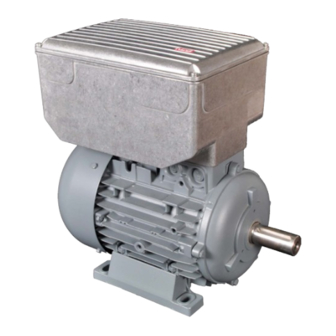
2 Product description The unit series G6M concerns to drive converters, which are optimized for open loop operation at controlled three-phase AC drives. The COMBIVERT G6M is specially designed for the installation at the motor. The units are equipped with an integrated EMC filter. This instruction manual describes only the power unit. -
Page 22: Product Features
Motor inverter Series: COMBIVERT G6M 0,75...1,5 kW @ 230 V / Power range: 0,75...2,2 kW @ 400 V Housing size: The COMBIVERT COMBIVERT G6M is characterized by the following features: • Operation at controlled three-phase AC drives. • Internal filter • following fieldbus systems are supported: Analog / Digital, EtherCAT, VARAN, PROFINET, IO-Link oder CAN •... -
Page 23: Part Code
PRODUcT DEScRIPTION 2.4 Part code x x G 6 x x x - x x x x 0: Standard Optionen A: Brake control A: G6L-G Open-loop without keyboard/display Control, keyboard, 0: G6-G Open-loop without keyboard/display Display 1: G6-G Open-loop with keyboard/display Switching frequency;... -
Page 24: Technical Data
3 Technical Data 3.1 Operating conditions 3.1.1 climatic conditions Storage Standard class Note Surrounding temperature EN 60721-3-1 -25…55 °C Relative humidity 5…95 % (without condensation) EN 60721-3-1 Storage height – – Max. 3000 m aboce sea level Transport Standard class Note Surrounding temperature EN 60721-3-2... -
Page 25: Mechanical Ambient Conditions
3.1.2 Mechanical ambient conditions Storage Standard class Note Amplitude of a vibration 0,3 mm (2…9 Hz) Vibration limits EN 60721-3-1 Acceleration 1 m/s² (9…200 Hz) Shock limit values EN 60721-3-1 40 m/s²; 22 ms Transport Standard class Note Vibration amplitude 3.5 mm (2…9 Hz) Vibration limits EN 60721-3-2 Acceleration amplitude 10 m/s²... -
Page 26: Electrical Operating Conditions
3.1.4 Electrical operating conditions 3.1.4.1 Equipment classification Requirement Standard class Note – EN 61800-5-1 Overvoltage category EN 60664-1 – Non-conductive pollution, occasional conden- Pollution degree EN 60664-1 sation when PDS is out of service. Table 5: Equipment classification 3.1.4.2 Electromagnetic compatibility The specified values are only valid for devices with mains choke EMc emitted interference Standard... -
Page 27: Unit Data Of The 230V Units
3.2 Unit data of the 230V units 3.2.1 Overview Inverter size Housing size Output rated power / kVA Max. rated motor power / kW 0,75 Input rated voltage 230 (UL: 240) N_ac Input voltage range 195...264 IN_ac Phases Mains frequency / Hz 50 / 60 ±2 Input rated current @ U... -
Page 28: Unit Data Of The 400V Units
3.3 Unit data of the 400V units 3.3.1 Overview Inverter size Housing size Output rated power / kVA Max. rated motor power / kW 0,75 Input rated voltage 400 (UL: 480) N_ac Input voltage range 305...528 IN_ac Phases Mains frequency / Hz 50 / 60 ±2 Rated input current @ U... - Page 29 „hard“ power systems or when under permanent drive load (continuous duty). For continuous duty (S1) drives with a medium duty of >60%, KEB provided the use of mains chokes with a terminal voltage (Uk) of 4%. The term "hard"...
-
Page 30: Maximum Load And Derating Depending On The Switching Frequency
3.4 Maximum load and derating depending on the switching frequency in % 220% 200% 180% 07G6M (4/8kHz) & 09/10G6M (4kHz) = Imax 160% 09G6M / 8 kHz 10G6M / 8 kHz 140% 120% 100% in Hz f0 = 0Hz fd = 6Hz Figure 1: Maximum load and derating depending on the switching frequency 3.5 Overload characteristic... -
Page 31: Mechanical Installation
3.6 Mechanical Installation 3.6.1 Dimensions and weight with braking resistor 92,75 203,4 185,5 Weight in kg Figure 3: Dimension and weights of the G6M... -
Page 32: Dimensions Of The Pg Cable Glands
3.6.2 Dimensions of the PG cable glands Thread sizes M25 x 1.5 M16 x 1.5 M16 x 1.5 M16 x 1.5 M16 x 1.5 M20 x 1.5 Figure 4: Overview of the PG cable glands... -
Page 33: Installation And Connection
4 Installation and connection 4.1 Overview of the cOMbIVERT G6M No. Name Description Diagnostic interface; RS232 / 485 interface with DIN66019-II reserved Mains input 3-phase (400 V mains input 1-phase (230 V Control terminal strip 32-pole – Type plate Inverter state... -
Page 34: Connection Of The Power Unit
TN, TT Personal protection RCMA with separator or RCD Earth leakage monitor type B Main fuses Type gG or MCCB Mains contactor Mains choke 07Z1B02-1000 or 09Z1B02-1000 KEB COMBIVERT Figure 7: Connection of the mains supply 230 VAC / 1-phase... -
Page 35: Ac Supply 400V / 3-Phase
(if required) type B Main fuses Type gG or MCCB Mains contactor Mains choke (optional) 07Z1B02-1000, 09Z1B02-1000 or 10Z1B04-1000 KEB COMBIVERT Figure 8: Connection of the mains supply 400 VAC / 3-phase 4.2.3 Line terminal strip X1A Name function cross-section... -
Page 36: Cross-Section Of The Supply Cable
4.2.4 cross-section of the supply cable The conductor cross-section of the supply line is determined by the following factors: • • input current of the drive converter • • used cable type / installation and ambient temperatures • • Applicable local electrical regulations The application engineer is responsible for the design! 4.3 connection of the motor The following steps must be observed if the inverter is not pre-installed on a motor. -
Page 37: Terminal Strip X1B Motor Connection
Connection for protec- 1.3 Nm Screw M4 tive earth 11 lb-inch Figure 10: Terminal block X1B 4.3.4 Wiring of the motor Legend KEB COMBIVERT Three-phase motor T1 T2 Temperature monitoring (optional) see chapter „Temperature detection" Figure 11: Wiring of the motor... -
Page 38: Connection Of A Braking Resistor
4.4 connection of a braking resistor Destruction of the frequency inverter if the vale has fallen below the Attention minimum brake resistance value! ► The minimum brake resistance value must not fall below! cAUTION Hot surfaces caused by load of the braking resistor! burning of the skin! ►... -
Page 39: Connection Of A Brake (Optional And Only For 400V Units)
4.5 connection of a brake (optional and only for 400V units) 4.5.1 brake control card Overview of the brake control card Name Description Connection of the control lines Output terminal / cable for the three mains phases Input terminal for the three mains phases HB + + Connection for the brake... -
Page 40: Wiring Of The Brake Control Card To The Inverter
4.5.2 Wiring of the brake control card to the inverter Overview for wiring of the brake control card Description The three mains phases are connected to input ter- minal X1D of the brake control card. The three mains phases must be connected from terminal X1E of the brake control card to terminal X1A of the frequency inverter. -
Page 41: Connection Of A Temperature Detection
4.6 connection of a temperature detection 4.6.1 Temperature detection terminals T1, T2 The KEB COMBIVERT is delivered with a PTC evaluation. The function corresponds to DIN EN 60947-8 and works in accordance with the following table: function of T1, T2... -
Page 42: Terminal Strip X1C Temperature Detection
4.6.2 Terminal strip X1c temperature detection Name function cross-section Tightening torque Connection for tempera- 0.14...1.5 mm² 0.22...0.25 Nm T1, T2 ture sensor AWG 28...16 2 lb-inch Figure 19: Terminal block X1C 4.6.3 Use of the temperature input in the PTc mode If the temperature input is operated in the PTC mode, the user can provide all possibilities within the resistance range specified in chapter „Temperature detection terminals T1, T2“. -
Page 43: Certification
EMC-directive (note 60204-1). 5.1.2 UL certifications An UL certification is in preparation. 5.2 further informations and documentation You find supplementary manuals and instructions for the download under "http://www.keb.de > Service & Downloads > Downloads". General instructions • EMC and safety instructions • Manuals for control boards, safety modules, fieldbus modules, etc. Instruction and information for construction and development •... - Page 44 Room 1709, 415 Missy 2000 725 Su Seo Dong Gangnam Gu 135- 757 Seoul Republic of Korea Société Française KEB SASU Tel: +82 2 6253 6771 Fax: +82 2 6253 6770 E-Mail: vb.korea@keb.de france Z.I. de la Croix St. Nicolas 14, rue Gustave Eiffel 94510 La Queue en Brie France KEB RUS Ltd.
Need help?
Do you have a question about the COMBIVERT G6M and is the answer not in the manual?
Questions and answers