JUKI SC-510 Engineer's Manual
Hide thumbs
Also See for SC-510:
- Engineer's manual (129 pages) ,
- Instruction manual (55 pages) ,
- Instruction manual supplement (43 pages)
Table of Contents
Advertisement
Advertisement
Table of Contents

Related Manuals for JUKI SC-510


Summary of Contents for JUKI SC-510
- Page 1 SC-510 ENGINEER’S MANUAL 40025322 No.E364-00...
- Page 3 PREFACE This Engineer’s Manual is written for the technical personnel who are responsible for the service and maintenance of the machine. The Instruction Manual for these machines intended for the maintenance personnel and operators at an apparel factory contains operating instructions in detail. And this manual describes “Standard Adjustment”, Adjustment Procedures”, “Results of Improper Adjustment”, and other important information which are not covered in the Instruction Manual.
- Page 4 SAFETY DEVICE Safety devices described below vary in accordance with the destination and specifications. Motor pulley cover Cover to prevent motor pulley and V belt from coming in contact with each other. Roll-in prevention pin Pin to prevent roll-in by V belt. Motor fan cover Cover to prevent motor fan from coming in contact...
-
Page 5: Table Of Contents
(1) Arrangement of connectors ..........................7 (2) How to use the standard operation panel ....................... 8 (3) Setting for functions of SC-510 ........................13 (4) Function setting list (Start level ; U : User's mode, S : Service mode) ............15 (5) Detailed explanation of selection of functions .................... -
Page 6: Specifications
3) SC-510 main unit only has the programming function and it is possible for SC-510 main unit only to program various input/output such as start, stop, etc. of the sewing machine by means of the external equipments or external input/output signals by using the optional input/output terminals. -
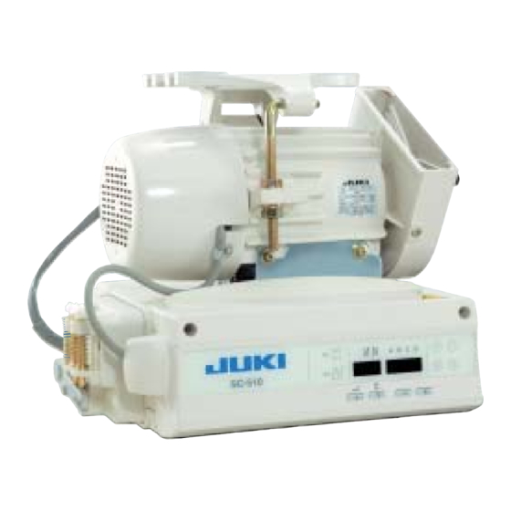
Page 7: Configuration
3. CONFIGURATION (1) SC-510/M51 1 : M51 (AC servo motor) 2 : Front cover 3 : Operation panel 4 : Pedal unit 5 : Power connector 6 : Motor connector − −... -
Page 8: Explanation Of Optional Control Panel
1) For the connecting destination of the connector, refer to the item (3) of 7. CONNECTING PROCEDURE WITH JUKI OPTIONAL DEVICES. 2) By connecting of CP-160, all displays of standard operation panel of SC-510 go off. However, error code No. is displayed only at the time of occurrence of error. -
Page 9: Explanation Of Control Panel Cp-160
(2) Explanation of control panel CP-160 1) Reverse stitching pattern When the sewing machine performs the free stitching operation, the machine performs the reverse stitching operation at the start and end of sewing. The reverse stitching operation can set the ON and OFF settings. Furthermore, single and double reverse stitching patterns can be selected. -
Page 10: Example Of Application
(3) Example of application 1) When the CP-160 is used together with the material end sensor (ED : optional), it can be used as a small edge-controller. mark 3 of the CP-160, turn ON material end sensor ON/OFF switch !2 (Method) Adjust the position to mark !3 of the automatic one-shot stitching. - Page 11 2) Label attaching is performed by the automatic one-shot stitching with the CP-160 mark !3 of the automatic one-shot stitching. mark 5 on the CP-160, and turn ON (Method) Select (Explanation) Number of stitches at the section CD can be set up to 500 stitches. If the stitch length is 2 mm, it is possible to sew approximately 1,000 mm (1 m).
-
Page 12: Control Box (Sc-510)
Following connectors are prepared when loosening the front cover fixing screws A of SC-510 and opening the cover. Connect the machine head connectors to the positions corresponding to each other so as to fit the devices mounted on the machine head. -
Page 13: How To Use The Standard Operation Panel
(2) How to use the standard operation panel switch Used for determining the contents of setting. When this switch is pressed, flashing stops and the contents of setting are determined. switch Used for changing the contents of setting. When this switch is pressed, changeable positions flash on and off. By pressing the switch, flashing position shifts in the right direction. - Page 14 Operating procedure of the sewing pattern 1. Reverse stitching pattern Reverse stitching patterns below can be set by using the operation panel. Reverse stitching patterns that can be set Reverse stitching at start display Sewing pattern Reverse stitching at end display [ Setting procedure of the reverse stitching ] Reverse stitching pattern Overlapped stitching pattern...
- Page 15 switch 1 to make number of (5) Press stitches display 8 flash on and off, and set the number of stitches for the respective processes of the stitching. switch 3 or switch 4 to (6) Press change the number of stitches. The number of stitches can be changed up to as many as 15 stitches for the A, B, C, and D processes respectively.
- Page 16 3. Special setting For material end sensor function, automatic thread trimming function, one-shot automatic stitching function and thread trimming prohibition function which are displayed in the front panel, it is possible to change the set value by directly moving to the function setting mode while the power is turned ON in addition to the normal function setting procedure. [ Moving procedure to the function setting mode ] switch 1, and press (1) Hold pressing...
- Page 17 3) Number of stitches to stop the sewing machine after detection of material end setting (Function setting No. 4) switch 1 to advance to the Press function setting No. 4. It is possible to change the set value with switch 3 or switch 4.
-
Page 18: Setting For Functions Of Sc-510
Functions can be selected and specified by means of the four setting switches and light emitting diode located inside the front cover of the SC-510. There are two modes of the user's level (indicated as U) and the service level (indicated as S) in the function setting modes. - Page 19 4. When you want to advance the setting No., press switch 2 to advance the setting No. Specified When you want to return the setting No., press switch 1 to return the setting No. (Caution) 1. When switch 1 (switch 2) is held pressing, the setting No.
-
Page 20: Function Setting List (Start Level ; U : User's Mode, S : Service Mode)
(4) Function setting list (Start level ; U : User's mode, S : Service mode) Indication of Start Setting Ref. Item Description level range function setting page Soft start The number of stitches to be sewn at a low speed when the soft-start 0 to 9 function function is used at the start of sewing. - Page 21 (Start level ; U : User's mode, S : Service mode) Start Setting Indication of Ref. Item Description page range function setting level Reversing Stop brake start angle of reverse revolution to lift needle input (Rsw) 0 to 359 brake start is set.
- Page 22 (Start level ; U : User's mode, S : Service mode) Indication of Setting Ref. Start Description Item range page function setting level Starting Position where the cloth presser starts lifting from pedal neutral position of position (Pedal stroke) –60 to –10 –...
- Page 23 (Start level ; U : User's mode, S : Service mode) Start Indication of Ref. Setting Description Item page level function setting range This function can specify the sewing speed of reverse feed stitching Function of Auto/ at the start of sewing. Manual change- 0 : The speed will depend on the manual operation by pedal, etc.
- Page 24 Selecting procedure machine head of the machine head with SC-510 (40027864). Max. number of rotation of the sewing machine head can be set. Setting of max. * Setting varies in accordance with resistance pack to be connected.
-
Page 25: Detailed Explanation Of Selection Of Functions
(5)Detailed explanation of selection of functions 1 Selection of the soft-start function (Function setting No. 1) The needle thread may fail to interlace with the bobbin thread at the start of sewing when the stitching pitch (stitch length) is small or a thick needle is used. To solve such problem, this function (called “soft-start”) is used to limit the sewing speed, thereby assuring successful formation of the starting stitches. - Page 26 8 Selection of the optional input/output function (Function setting No. 12) Operation keys array 1. Select function No. 12 with the operating procedures described in the item of how to change over the function setting mode (1) to (4). Select the items of "End", "in" and "ouT" with keys 3 and 4. [When "in"...
- Page 27 Input function list Function Function item Abbreviation Remarks code (Standard setting) No function Every time the switch is pressed, normal feed stitching by half Needle up / down compensating stitching stitch is performed. (Same operation as that of up / down compensating stitching switch on the panel.) Back compensating stitching Reverse feed stitching is performed at low speed while the...
- Page 28 CN50 CN51 (Output) (Input) Input/output signal Voltage Input connector 7-segment Jumper for power Connector No. Pin No. Function display No. voltage setting Vcc4 Power voltage selected with W4 CN51-1 Optional input 1 Optional input 2 Vcc4 selects +5V, +12V a n d + 2 4 V w i t h t h e Vcc4 Power voltage selected with W4 setting of W4.
- Page 29 9 Sewing counting function (Function setting No. 14) The function counts up every time thread trimming is completed and counts the number of completion of the sewing process. This can be realized together with the CP-160 control panel. Refer to the explanation of the control panel. 0 : off Sewing counting function is inoperative.
- Page 30 !5 Function of changeover of compensating switch on the operation panel function (Function setting No. 22) Function of compensation switch on the operation panel of CP-160 can be changed over to needle up / down compensating stitching or one stitch compensating stitching. 0 : Needle up / down compensating stitching 1 : One stitch compensating stitching !6 Function of input of presser for standing work (Function setting No.
- Page 31 !9 Function of reverse feed stitching on the way (Function setting Nos. 30 to 33) Functions of the limit of number of stitches and thread trimming command can be added to the touch back switch on the sewing machine head. Function setting No.
- Page 32 @0 Number of rotations of thread trimming (Function setting No. 36) Number of rotations of sewing machine at the time of thread trimming is set. Setting range 100 to 250 rpm @1 Number of rotation of one-shot stitching (Function setting No. 38) This function can set, by the pedal operation of one time, the sewing speed of one-shot stitching when the sewing machine continues stitching until completing the number of stitches specified or detecting the material end.
- Page 33 2 Compensation of off-timing of solenoid for reverse feed stitching at the start of sewing (Function setting No. 52) Off-timing of solenoid for reverse feed stitching at the start of sewing can be compensated by the unit of angle. Adjusting range –...
- Page 34 #0 Function of holding predetermined upper / lower position of the needle bar (Function setting No. 58) When the needle bar is in the upper position or in the lower position, this function holds the needle bar by applying a brake slightly. 0 : off Function of holding predetermined upper/lower position of the needle bar is ineffective.
- Page 35 #5 Selection of thread trimmer and additional device (Function setting No.65) Thread trimming control corresponding to the machine head is selected. When additional device is mounted, device function is set. F U n Setting item is selected by operating 3 and 4. LED 3-digit display LED 4-digit display End of setting (Setting returns to the...
- Page 36 Contents of selection of thread trimmer and additional device, and list of parameter setting UT1 : It is possible to set the model installed with device such as thread trimming device, cutter, etc. as the additional device to the machine head. Device setting LED 3-digit display LED 4-digit display...
- Page 37 Parameter setting LED 3-digit display LED 4-digit display Description of device setting Remarks Thread rack remaining thread output OFF 185fl : from Up angle setting position off Number of stitches of condensation start 30 stitches waiting setting Number of stitches of condensation setting 10 stitches Normal number of stitches setting 2 stitches Number of stitches of short stitch...
- Page 38 #6 Simplified program setting (Function setting No. 66) Valid/invalid of motion of simplified program, and input, change, etc, of program are set. For the details, refer to "(2) of 9. How to use the simplified program function". #7 Auto hemmer control changeover (Function setting No. 67) Auto hemmer control used with MF is selected.
- Page 39 $2 Retry function (Function setting No. 73) When the retry function is used, if the sewing material is thick and not piereced with needle, this function makes the needle pierce in the material with ease. 0 : Normal 1 : Retry function is provided. $3 With/without MF thread trimming device (Function setting No.
- Page 40 $8 Initial UP stop position move function (Function setting No. 90) Whether valid or invalid of function to automatically return to UP stop position immediately after turning ON the power can be set. 0 : Invalid 1 : Valid $9 Function of reducing speed of reverse feed stitching at the start of sewing (Function setting No. 92) Function to reduce speed at the time of completion of reverse feed stitching at the start of sewing : Normal use depending on the pedal condition (Speed is acceralated to the highest without a break.) This function is used when temporary stop is used properly.
-
Page 41: Automatic Compensation Of Neutral Point Of The Pedal Sensor
(7) Initialization of the setting data All contents of function setting of SC-510 can be returned to the standard set values. (1) Pressing all switches 1, 2 and 3, turn ON the power switch. -
Page 42: Changing Procedure Of The Pedal Type
By setting to KFL type, when depressing the back part of pedal, thread trimming motion is performed at a shallow position. For changing procedure, follow (3) Setting for functions of SC-510, and change according to the description below. @4 Pedal presser lifting function (Function setting No. 50) Pedal type setting can be changed. -
Page 43: Connecting Procedure With Juki Optional Device
7. CONNECTING PROCEDURE WITH JUKI OPTIONAL DEVICE (1) Connection of the pedal of standing-work machine 1) Connect the connector of PK70 1 to connector 2 (CN39 : 12P) of SC-500. 2) Tighten the cord of PK70 together with other cords with cable clip band 3 attached to the side of the box after passing it through the cable clamp. -
Page 44: External Input/Output Connector (Signal Connector For Extension)
8. EXTERNAL INPUT/OUTPUT CONNECTOR (SIGNAL CONNECTOR FOR EXTENSION) (1) Encoder output connector (CN40) CN40 Signal name Description Electric spec. pin No. UDET(N) "LOW" is output when upper position +5V 100mA angle from synchronizer is reached. DDET(N) "LOW" is output when lower position +5V 100mA angle from synchronizer is reached. -
Page 45: How To Use The Simplified Program Function
(1) Simplified program function SC-510 does not use the exclusive input device or the like and has the function that can create the simplified programs which take in the signals from the outside, output the signals to the outside, and control the sewing machine head by SC-510 main unit only. -
Page 46: Sequence Of Start And Input
(2) Sequence of start and input Start the setting mode and select function No. 66 in accordance with "Setting for functions of SC-510". When No. 66 is selected, indication below appears. Press + or - key to select program No. -
Page 47: Command Input
(3) Command input Indications and inputting procedure at the time of command input are explained below. Input the program command to each step at the time of step input after selection of program, the transition (sequence) below is the transition (sequence) for 1 (one) command. Contents of display and input items are explained below. -
Page 48: Simplified Program Command List
(4) Simplified program command list The list below is that of command and parameter used in the simplified program function. Parameter 1 Function Abbreviation Command Output Setting Input Setting code setting range setting range Completion Valid oH.1 to 17 Invalid Invalid oL.1 to 17 DELy... - Page 49 Parameter 2 Setting Setting range Remarks range Invalid Initial value Delay time (d.) In case set value is "0", command is invalid. In case of other set 1 to 999 X 1 mS value, step moves to next one after lapse of delay. 1 to 20 Delay time (d.) 0 : Waiting input until...
- Page 50 Parameter 1 Function Abbreviation Command Output Setting Input Setting code setting range setting range UP stop command Valid oH.1 to 17 Invalid Invalid oL.1 to 17 Needle up/down Valid oH.1 to 17 Invalid Invalid command oL.1 to 17 Rsw command Valid oH.1 to 17 Invalid...
- Page 51 Parameter 2 Setting Setting range Remarks range Delay time (d.) 0 : Without delay UP position stop command (speed designated with other command 1 to 999 X 1mS is neglected.) Command is executed without delay time with delay time "0". For others, UP position stop command is valid within set delay time and command is invalid after lapse of delay time.
-
Page 52: Simplified Program Information Input Setting Code List And Connector Location List
(5) Simplified program information input setting code list and connector location list List below is the list of port input code indicated in 7-segment LED at the time of input, connector No. and pin No. on p.c.b., pin assignment, function, etc. Input list Port input Signal name... - Page 53 Input list Port input Signal name Function Connector No. and Pin No. Remarks code pin No. on p.c.b. opo12 Input of optional output-12 Output signal of optional output-12 can be internally inputted. opo13 Input of optional output-13 Output signal of optional output-13 can be internally inputted. opo14 Input of optional output-14 Output signal of optional output-14 can be internally inputted.
-
Page 54: Setting Procedure Of Optional Power And Setting Procedure Of Jumper For Input Changeover
(6) Setting procedure of optional power and setting procedure of jumper for input changeover Lists below are those of setting procedure of power voltage of optional connectors. By setting respective jumper wires, +5V, +12V and +24V can be used. * +5V has been set at the time of delivery from factory. 1. - Page 55 Explanation of input changeover jumper switch It is possible to change 4 inputs among the optional inputs by changing the setting of jumpers W5 to W8. Jumper No. Pin No. Signal Input connector Remarks Digital input of +5V CN51-4 3Pin Analog input of +5V (1) CN51-4 3Pin This input becomes analog signal input.
- Page 56 Signal system pin assignment of optional input/output connectors List below is the list showing the relation between connector for optional and port input/output code. Be sure to keep the items of caution for use. 3. Input connector This optional input can be connected to transistor output of PLC, relay output, open collector output, push button switch, etc.
- Page 57 5. Input/output circuit Input circuit 入力回路 +5 +5 4.7KΩ 4.7K 1KΩ 0.1μ 0.1µF +5V、+12V、+24V Output circuit +5V, +12V, +24V ジャンパワイヤーで設定 Voltage set with jumper wire された電圧。 出力回路 − −...
-
Page 58: Transition (Sequence) Diagram Of No. 66 Simplified Program Function
(7) Transition (sequence) diagram of No. 66 simplified program function Transition (sequence) of respective input modes is as shown below. P r o _ Transition STEP ▲▼キー +キーで遷移 with + key STEP ▼キー で遷移 _ E n d _ o F F P r o *. - Page 59 − −...
- Page 60 − −...
- Page 61 − −...
-
Page 62: Connector Connection Diagram
10. CONNECTOR CONNECTION DIAGRAM (1) Solenoid for machine head Layout of CN36 pins CN36 Name of signal Pin No. TRMD TRM (Thread trimming) Approx. 7.5 Ω TRM COM BTD COM BT (Touch back) Approx. 6.5 Ω WPD COM WP (Wiper) SUB BTD Approx. -
Page 63: Optional Cord
(3) Optional cord Relay cord A asm. for the standing sewing machine (Part No. M9701351AA0) Approx. 1.5m 1) Wiring diagram of variable pedal PK-70 and -71 CN39 Brown Orange Variable resistor Used by variable voltage for speed Yellow between 1 to 2V (Increasing / decreasing Switch for Green... -
Page 64: Maintenance
2) Wiring diagram of fixing max. speed CN39 Brown Orange Variable resistor for speed Yellow Green Switch for lifting presser foot Blue Purple Switch for thread trimming Gray White Switch for high-speed Light blue Pink Switch for low-speed Black (Caution) When decreasing the speed of the high-speed SW, use the max. speed limitation variable resistor on the panel. - Page 65 [ Replacing F1 fuse on CTL circuit board (solenoid protection fuse) ] 1) Loosen two setscrews in the front cover and open the cover after checking that the power has been turned OFF. 2) Replace 5A F1 fuse on CTL circuit board with a fuse of the same capacity supplied as accessories.
-
Page 66: Changing Procedure Between 100V To 120V And 200V To 240V
(2)Changing procedure between 100V to 120V and 200V to 240V (Possible only for the voltage changeover type) WARNING : To prevent personal injuries caused by electric shock hazards or abrupt start of the sewing machine, carry out the work after turning OFF the power switch and a lapse of 5 minutes or more. To prevent accidents caused by unaccustomed work or electric shock, request the electric expert or engineer of our dealers when adjusting the electrical components. - Page 67 − −...
-
Page 68: Control Voltage Check Terminal Of Ctl Circuit Board
12. ERROR CODES In case of the following, check again before you judge the case as trouble. Phenomenon Cause Corrective measure When tilting the sewing machine, the When tilting the sewing machine without Tilt the sewing machine after turning OFF buzzer beeps and the sewing turning OFF the power switch, Action the power. -
Page 69: Error Code List
(1) Error code list Description of error detected Cause of occurrence expected Items to be checked E000 Execution of data initialization • When the machine head is changed. (This is not the error.) • When the initialization operation is executed E003 Disconnection of synchronizer •... - Page 70 MEMO − −...
-
Page 71: Block Diagram
13. BLOCK DIAGRAM (FOR EXTENSION INPUT) (FOR EXTENSION OUTPUT) (ENCODER FOR EXTENSION OUTPUT) (OPTIONAL PCB I/F) (FOR MITSUBISHI ENCODER) (STANDING-WORK PEDAL SENSOR) (HEAD MAGNET DRIVE) (PEDAL SENSOR) (SYNCHRONIZER) (HEAD DISCRIMINATION) (CP-160) (ENCODER) CN35 (+5V, EACH CONTROL SIGNAL) (110V/220V CHANGEOVER) (MOTOR DRIVE) (REGENERATIVE RESISTANCE) POWER INPUT CABLE LA ASM "* mark :"... -
Page 72: Reference> Table Of Digital Display
<REFERENCE> TABLE OF DIGITAL DISPLAY Table of digital display Numeral Digital display Numeral Digital display Numeral Digital display Numeral Digital display − −... - Page 73 FAX : (81)3-3430-4909 • 4914 * The description covered in this engineer's manual is subject to change for improvement of the commodity without notice. Copyright C 2004 JUKI CORPORATION. All rights reserved throughout the world. 04 · 09 Printed in Japan (E)
Need help?
Do you have a question about the SC-510 and is the answer not in the manual?
Questions and answers