
Related Manuals for JUKI IP-100


Summary of Contents for JUKI IP-100
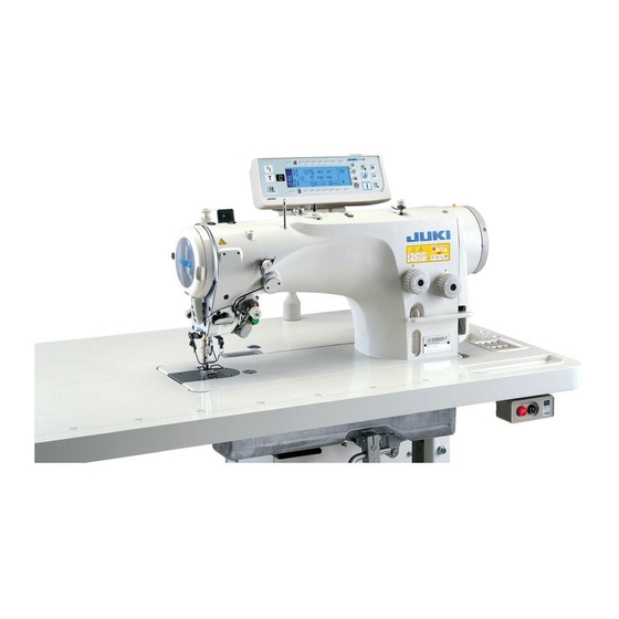
- Page 1 Computer-controlled, Direct-drive, High-speed, 1-needle, Lockstitch, Zigzag Stitching Machine LZ-2290A Series IP-100 / SC-915 ENGINEER’S MANUAL 40011067 No.E355-00...
- Page 2 Instruction Book intended for the maintenance personnel and sewing operators at a sewing factory. All personnel engaged in repair of LZ-2290A Series • IP-100 / SC-915 are required to carefully read Section 2 “Standard Adjustment” which contains important information on the maintenance of LZ-2290A Series • IP-100 / SC-915.
-
Page 3: Table Of Contents
CONTENTS 1. SPECIFICATIONS ......................1 (1) Specifications of the machine head ...................... 1 (2) Stitch pattern table ..........................2 (3) Function list ............................3 (4) Cautions in operation ..........................3 2. NAME OF EACH COMPONENT ..................4 3. STANDARD ADJUSTMENT ..................6 (1) Height and inclination of the feed dog .................... - Page 4 6. OPERATION PANEL ....................76 (1) Names of the respective sections ....................... 76 (2) Information ............................78 (3) Matters that demand special attention regarding the operation panel, IP-100 ........92 7. SPECIFICATIONS OF SC-915 ..................93 8. FUNCTION SETTING PROCEDURE OF SC-915 ............93 (1) How to change over to the function setting mode ................
-
Page 5: Specifications
Automatic reverse stitching Lubrication Lubrication system to oil tank for hook Full non-lubrication lubrication JUKI New Defrix Oil No. 1 is used. (Equivalent to ISO VG7) Plunger pump is employed. 5.5 mm Lift of the presser foot (by hand lifter) -
Page 6: Stitch Pattern Table
(2) Stitch pattern table Number of stitches Max. zigzag width Name of pattern Stitch pattern Remarks for pattern Straight stitch – Standard zigzag stitch 2-step zigzag stitch 3-step zigzag stitch Scallop Standard (right) scallop ( ) Crescent scallop ( ) Equal-width scallop (... -
Page 7: Function List
(3) Function list Free Overlapped Conden- Custom Custom Zigzag Pattern Continuous Cycle Program Conden- stitching stitching sation pattern pattern width and register stitching stitching stitching sation custom (Internal (Smart stitch base register register Sewing memory) media) line setting Straight stitch Standard 2-step 3-step... -
Page 8: Name Of Each Component
2. NAME OF EACH COMPONENT !2 2 !7 7 !8 8 !4 4 Bobbin winder 1 Needle thread draw-out device 7 Pedal 8 Knee lifter lever !5 Tension controller No. 1 (LZ-2290A (U)-7) 2 Wiper switch (WB/CB type) 9 Power switch !6 Thread stand 3 Thread take-up cover !0 TB switch... - Page 9 1 Needle thread draw-out device (LZ-2290A (U)-7) This device draws out needle thread at the time of thread trimming. 2 Wiper switch (WB/CB type) This switch is used to wipe needle thread after thread trimming from the cloth by means of the wiper signal which is output from the PSC box.
-
Page 10: Standard Adjustment
3. STANDARD ADJUSTMENT (1) Height and inclination of the feed dog Standard Adjustment Standard height : 1.2 mm : LZ-2290ASS, LZ-229ADS Reference for the height and inclination of the : 1.4 mm : LZ-2290ASU, LZ-2290ADU feed dog Inclination : The feed dog should be almost leveled ™... - Page 11 Adjustment Procedures Results of Improper Adjustment 1) Set the feed amount to 0 mm. Feed amount is regulated to (max. 2 ™ Perform the adjustment of the mm at the time of delivery.) inclination of the feed dog according 2) Adjusting the height of the feed dog to the sewing process.
-
Page 12: Adjusting The Feed Amount
(3) Adjusting the feed amount Standard Adjustment LZ-2290ASS, DS Feed crank stud Timing mark Reverse feed amount regulation metal fitting Feed adjusting link LZ-2290ASU, DU Feed converting Normal feed amount arm A (asm.) Feed spring hook regulation metal fitting (4) Position of the feed dog Standard Adjustment Condition : Feed amount : maximum Feed bar... - Page 13 Adjustment Procedures Results of Improper Adjustment ™ If the timing marks are not aligned [Feed “0” adjustment] with each other, the actual feed 1) Set the stitch length dial at “0”. amount will be different from the 2) Loosen screw 1, and align the timing mark on the feed crank stud feed amount specified on the stitch with that on the feed crank stud support.
-
Page 14: Adjusting The Slippage Of Materials (For Asu And Adu)
(5) Adjusting the slippage of materials (For ASU and ADU) Standard Adjustment Standard state of engraved marker dot of vertical feed link shaft Standard height of feed dog Operator’s side Minus slippage Sewing direction of material Upper material θ Lower material “0”... - Page 15 Adjustment Procedures Results of Improper Adjustment ™ The height 1.4 mm of the feed dog 1) To adjust the height and inclination of the feed dog, loosen setscrews 1 in the vertical feed link shaft and turn vertical feed link shafts 2 has been factory-set at the time of and 3 with a screwdriver.
-
Page 16: Adjusting The Origin Of The Needle Rocking Motor
(6) Adjusting the origin of the needle rocking motor Standard Adjustment ™ Adjustment of the origin is performed in case the needle rocking amount in terms of the center is not equal when (7) Adjusting the needle entry position is performed, or the motor or the sensor is required to be replaced. - Page 17 Adjustment Procedures Results of Improper Adjustment 1) Remove four setscrews 1 in the needle rocking motor cover. 2) Remove three setscrews 2 and counter sunk screw 3. (At this time, loosen setscrew 4 in the needle bar support base shaft connecting stud as well. Refer to the item “(7) Adjusting the needle entry position”.) * When assembling, after temporarily tightening screws 3 and 2, tighten in the order of 3 and 2.
-
Page 18: Adjusting The Needle Entry Position (In Terms Of Needle Rocking Direction)
(7) Adjusting the needle entry position (In terms of needle rocking direction) Standard Adjustment Needle bar support base shaft connecting stud (8) Adjusting the needle entry position (In terms of longitudinal direction) Standard Adjustment Needle enters the center of needle slot. Hole for adjusting needle entry position (9) Adjusting the longitudinal play at the needle bar... - Page 19 Adjustment Procedures Results of Improper Adjustment 1) Loosen setscrews 2 and remove bobbin winder unit 1. ™ Thread will not be uniformly tensed when the needle throws to the right 2) Set both zigzag width and stitch base line to the position of "0" in the and left, or thread breakage or hook adjusting mode.
-
Page 20: Position Of The Needle Bar Connection Guide
(10) Position of the needle bar connection guide Standard Adjustment Needle bar Needle bar connection guide support base Needle bar crank rod guide (11) Height of the needle bar Standard Adjustment Conditions : Zigzag width : “0” Position of needle position changing lever : Center ™... - Page 21 Adjustment Procedures Results of Improper Adjustment 1) Loosen the screw in the needle bar support base shaft connecting stud referring to "(7) Adjusting the needle entry position (in terms of needle rocking direction)". 2) Remove the thread take-up cover, thread take-up and face plate. Then loosen screws 2 and 3 in the needle bar connection guide together with screws 4 and 5 in the needle bar crank rod guide.
-
Page 22: Adjusting The Needle-To-Hook Timing And The Needle Guard
(12) Adjusting the needle-to-hook timing and the needle guard Standard Adjustment Information screen 1. Hook adjusting mode Hook adjusting mode setting screen <Straight stitch> Hook adjusting mode <Standard zigzag stitch> ™ Lifting amount of the needle (bar) : 3.4 mm (Adjust with engraved marker dot 2 of timing gauge E.) Woodruff plate ™... - Page 23 Adjustment Procedures Results of Improper Adjustment ™ If the timing relation between the 1. Hook adjusting mode 1) When performing the hook adjusting, turn ON the power. When the needle needle and the blade point of the hook bar is not in UP position, turn the handwheel to bring the needle bar to its UP is excessively advanced, smaller position.
-
Page 24: Position Of The Bobbin Case Stopper
(13) Position of the bobbin case stopper Standard Adjustment ™ The bobbin case stopper 2 should be located within the range from the position at which top end A of the bobbin case stopper is aligned with line B to the position that is 0.5 mm away from line B in direction C. - Page 25 Adjustment Procedures Results of Improper Adjustment 1) Loosen screw 1 and adjust the position of bobbin case stopper 2 by turning the entire unit of the bobbin case stopper. (Caution) After the position of bobbin case stopper 2 has been adjusted, turn the bobbin case by fingers in the reverse direction of rotation to confirm that the bobbin case will never slip out of the small claw of bobbin case stopper Adjustment Procedures...
-
Page 26: Position Of The Thread Tension
(15) Position of the thread tension Standard Adjustment Striking face on the machine arm Thread tension controller * Felt of the thread tension controller is a consumable part. Replace it when it is consumed. Part No. of felt : 22528509 (16) Position of the pre-tension Standard Adjustment Setscrew nut 1... - Page 27 Adjustment Procedures Results of Improper Adjustment 1) Loosen screw 1, and adjust the position of the thread tension in the state that the thread tension controller is pushed to the striking face on the machine arm. Adjustment Procedures Results of Improper Adjustment 1) Loosen setscrew nut 1, and adjust the longitudinal position of ™...
-
Page 28: Position Of The Thread Take-Up Spring Guard
(17) Position of the thread take-up spring guard Standard Adjustment Tension disk Stopper rubber Thread take-up spring guard (18) Installing the thread take-up thread guide B Standard Adjustment (19) Installing the thread take-up Standard Adjustment ™ Fix the thread take-up with pressed in the direction of rotation. Direction of rotation −... - Page 29 Adjustment Procedures Results of Improper Adjustment 1) Loosen screw 1, and adjust the position of the thread take-up spring guard so that the stopper rubber 2 does not come in contact with the outer periphery of the thread tension disk 3. Adjustment Procedures Results of Improper Adjustment 1) Loosen the screw 1, and adjust the position of the thread...
-
Page 30: Installation Of The Presser Foot
(20) Installation of the presser foot Standard Adjustment ™ The top surface of the throat plate should be closely fitted on the reverse side of the presser foot Screw Throat plate (21) Installing and adjusting the bobbin winder unit Standard Adjustment ™... - Page 31 Adjustment Procedures Results of Improper Adjustment 1) Put the pressser foot 4 in the presser bar 3, and insert screw ™ If the presser foot is not closely 1, At this time, do not tighten screw 1. fitted on the throat plate, the 2) Turn the handwheel until the feed dog 5 descends under the material will not be fed straight and the material will flop causing...
-
Page 32: Adjusting The Amount Of Oil In The Hook (Ass/-7, Asu/-7)
(22) Adjusting the amount of oil in the hook (ASS/-7, ASU/-7) Standard Adjustment Race surface Decrease Increase Approx. 1.5 mm Appropriate amount of oil (large) Race surface L-shaped spanner Approx. 0.5 mm Oil splash on a sheet of paper while the machine is operating for 5 Appropriate amount seconds (4,000 rpm) - Page 33 Adjustment Procedures Results of Improper Adjustment The amount of oil in the hook can be adjusted with oil amount adjusting screw 1. ™ When oil wick is stained, decrease 1) Adjusting procedure of oil amount in the hook or Turning (clockwise) oil amount adjusting screw 1 increases the oil unstableness of oil amount will amount in the hook and turning (counterclockwise) it decreases the oil result.
-
Page 34: Initial Position Of The Moving Knife
(24) Initial position of the moving knife Standard Adjustment ™ Moving knife pin 1 should be aligned with marker dot 2. ™ Acceptable range of the position of moving knife is as wide as the marker dot. Marker dot Internal mechanism of thread trimming unit Latch (Rearmost) - Page 35 Adjustment Procedures Results of Improper Adjustment 1) Loosen nut 3 in the knife driving arm 7 , and adjust the initial ™ If the initial position of the moving position of the moving knife. knife is not properly adjusted, the Loosen/tighten nut 3 after roller 4 has fitted in the groove on moving knife will fail to cut the the thread trimming cam 8 by pressing roller arm 6 with...
-
Page 36: Installing/Removing The Knife Unit
(26) Installing/removing the knife unit Standard Adjustment Knife unit Knife unit (27) Stop position of the needle after thread trimming (Needle UP stop) Standard Adjustment ™ The standard stop position of the needle (position at which the marker dot engraved on the machine arm is aligned with the white marker dot engraved on the handwheel) is when the marker line engraved on the thread take-up is aligned with the marker line engraved on the face plate (60˚). - Page 37 Adjustment Procedures Results of Improper Adjustment 1) Loosen screw 1 and remove fixing plate 2. 2) Remove screw 3, and the knife unit will come off. Installation is carried out analogously in reverse order. (Caution) When installing the knife unit, take care to allow pin 5 of moving knife (asm.) 4 to securely rest on knife yoke (asm.) 6.
-
Page 38: Position Of The Automatic Reverse Stitching Magnet
(29) Position of the automatic reverse stitching magnet Standard Adjustment ™ Max. feed amount LZ-2290ASS, ADS = 5 mm LZ-2290ASU, ADU = 2.5 mm Standard delivery : 2 mm ™ Max. reverse feed amount LZ-2290ASS, ADS = 4 mm LZ-2290ASU, ADU = 2.5 mm Standard delivery : 2 mm (30) Adjusting the thread tension releasing solenoid Standard Adjustment... - Page 39 Adjustment Procedures Results of Improper Adjustment 1) Loosen two setscrews 1. Adjust the position by moving automatic reverse stitching magnet 2 itself. 2) When the reverse feed lever is pressed down and plunger 3 moves in the direction a at the maximum feed amount, cushion rubber4 should be able to slightly rotate.
-
Page 40: Adjusting The Stitch Length Dial
(31) Adjusting the stitch length dial Standard Adjustment (a) Assembling the stitch length dial (b) Assembling the condensation dial The name of part or the like in the parentheses ( ) in the description is the explanation in case of (b) Assembling the condensation dial. 1) Apply the exclusive grease to feed adjusting screw 1 and feed adjusting shaft 2 (condensation adjusting shaft !4 ) . - Page 41 Adjustment Procedures Results of Improper Adjustment ™ When the work of step 7) (work of step 9) has been completed, turn stitch length dial 8 (condensation dial 9) and check that the dial moves as specified in the scale. ™ When the marker dot engraved on the machine arm cannot be adjusted, check and re-adjust from the work of step 5).
-
Page 42: Adjusting The Lubrication Mechanism (Ass And Asu Only)
(32) Adjusting the lubrication mechanism (ASS and ASU only) Standard Adjustment ™ Forced lubrication is performed to the hook by means of the plunger pump placed in the hook shaft front bushing in the machine head (ASS, ASU) Oiler Upper marker line Lower marker line (33) Adjusting the position of the thread draw-out wire (For the machine with thread trimmer only) - Page 43 Adjustment Procedures Results of Improper Adjustment 1) When the top end of oil amount indicating rod 3 comes down to the lower marker line of oil amount indicating window 2, remove oil inlet cap 1 and fill oil up to the upper marker line of oil amount indicating window 2.
-
Page 44: Adjusting The Stroke Of The Thread Draw-Out Wire (For The Machine With Thread Trimmer Only)
(34) Adjusting the stroke of the thread draw-out wire (For the machine with thread trimmer only) Standard Adjustment Not to come in contact with each other Not to come in contact with each other (35) Installing the wiper base (WB only) Standard Adjustment ™... - Page 45 Adjustment Procedures Results of Improper Adjustment 1) Loosen setscrew 1 with hexagon wrench key 3 supplied with the machine as accessory. 2) Turn the thread draw-out wire together with thread draw-out wire installing base 2 and adjust up or down the top end of thread draw-out wire 4.
-
Page 46: Adjusting The Wiper Solenoid (Wb Only)
(36) Adjusting the wiper solenoid (WB only) Standard Adjustment ™ When the wiper solenoid 3 is OFF (in the normal state), the pin A should be lightly fitted onto the leftmost end of the slot while providing no clearance between them. (State A) Confirm that the pin comes in contact with the rightmost end of the slot at position C when the wiper solenoid is actuated (when it is pressed in direction B). - Page 47 Adjustment Procedures Results of Improper Adjustment 1) Loosen setscrews 1 and 2 when wiper solenoid 3 is not actuated (OFF). Adjust pin A to state A by moving the entire unit of wiper solenoid 3. * For CB type, refer to 2) CB type of (37) Position of the wiper. Adjustment Procedures Results of Improper Adjustment 1.
-
Page 48: Cb Type
2) CB type Standard Adjustment Going Going Needle Needle (extreme left of (extreme left of 8 mm zigzag 8 mm zigzag Return Return width) width) 0.5 to 1 mm Wiper link A To be almost parallel To be convex by 1 to 3 mm 0 to 1 mm To be flush Ratchet mechanism... - Page 49 Adjustment Procedures Results of Improper Adjustment 1. Adjusting the moving path of the wiper 1) Set the needle to UP stop position. Adjust the white marker dot of handwheel 1 to the marker dot of pulley cover 2. When wiper link A is moved by hand, wiper 3 slides to and fro by means of ratchet mechanism.
-
Page 50: Procedures Of Disassembing/Assembling And Cautions
4. PROCEDURES OF DISASSEMBING/ASSEMBLING AND CAUTIONS (1) Adjusting and assembling of the gear box (large) Procedures of disassembling/assembling ™ Loosen setscrews 1 and remove the gear box large cover 6. ™ Centering the horizontal feed cam 1) Remove feed spring 7. 2) Loosen setscrew 3 in horizontal feed cam rod 4. - Page 51 Caution in disassembling Caution in assembling ™ For removing/installing the gear box cover 6, be sure to refer ™ The horizontal feed cam and to the item “(4) Removing/installing the gear box cover” and hook driving gear are mounted carefully perform the work. in the gear box (large).
-
Page 52: Replacing The Motor
(2) Replacing the motor Procedures of disassembling/assembling 1) Loosen the setscrews in the handwheel in the order of screw No. 2 2 and screw No. 1. 1. 2) Remove four setscrews 4 in pulley cover 3 with the hexagon wrench key of 4 mm. 3) Remove the pulley cover 3 while paying attention to LED 5 of the synchronizer. - Page 53 Caution in disassembling Caution in assembling (Caution) (Caution) 1. There is the release secton A at the shaft 1. Take care of the dust when replacing the section of the encoder case B in the rear motor and install the handwheel quickly. of the motor.
-
Page 54: Replacing The Timing Belt
5) When peeling off safety label 1 in the front of machine bed, there is a rubber plug inside. Remove the rubber plug and fill the gear box with 190 cc of (JUKI genuine) Defrix Oil No. 2. − −... - Page 55 0.5 mm Caution in disassembling Caution in assembling (Caution) Do not open the gear box unless a trouble occurs. ™ Replace the packing with a new one. * JUKI genuine oil Defrix Oil No. 2 : MDFRX270000 − −...
-
Page 56: Disassembling/Assembling The Needle Bar Support Base Shaft (Asm.)
(5) Disassembling/assembling the needle bar support base shaft (asm.) Procedures of disassembling/assembling Structure of components Needle bar support base shaft rear metal A Thrust bush Needle bar support base shaft (asm.) Lock nut Lock washer Slide resistance screw Needle bar support base shaft −... - Page 57 Caution in disassembling Caution in assembling * Slide resistance spring 2 which greatly affects the needle rocking performance is mounted in needle support base shaft rear metal B 1. Do not perform the adjustment or the like unless it is necessary. <...
- Page 58 Procedures of disassembling/assembling Knife − −...
- Page 59 Caution in disassembling Caution in assembling 2. Removing the thread take-up cover base Loosen two fitting screws 2 in thread take-up cover base 1 and remove thread take-up cover base 1. 3. Removing the thread take-up Loosen three setscrews 3 in the thread take-up and remove ™...
- Page 60 Procedures of disassembling/assembling Needle bar upper Needle bar upper metal section metal section − −...
- Page 61 Caution in disassembling Caution in assembling 2) Removing the presser bar components Remove the presser foot setscrew and remove the presser foot. Loosen presser bar guide bracket screw 1 and remove presser spring regulator 2, presser guide bar 3, presser spring 4 and presser bar 5.
- Page 62 Procedures of disassembling/assembling Apply grease. − −...
- Page 63 Caution in disassembling Caution in assembling 7) Removing the needle rocking motor unit. Remove screws 1 and 2, draw out needle bar support base shaft 7 from the needle bar support base shaft bracket, and remove the needle rocking motor unit from the machine arm. ™...
- Page 64 Procedures of disassembling/assembling Needle bar bracket guide Needle bar crank rod guide Longitudinal Engraved marker play Needle feed unit base − −...
- Page 65 Caution in disassembling Caution in assembling 9) Adjusting the longitudinal position of the needle bar 1. Attach the throat plate, attach a needle to the needle bar, lightly press support base shaft guide pin B 1 so as to remove the play of the needle bar, and temporarily tighten setscrew 2 in the support base shaft guide pin B.
- Page 66 Procedures of disassembling/assembling By loosening setscrews 4 in the needle bar support base shaft bracket collar, the connecting shaft slides. − −...
- Page 67 Caution in disassembling Caution in assembling 4) Loosen setscrews 4 in the needle bar support base shaft bracket collar. By loosening setscrews 4 in the needle bar support base shaft bracket collar, connecting shaft 5 slides to the right or left. ™...
-
Page 68: Maintenance
5. MAINTENANCE (1) Replacing procedure of the printed circuit board 1. FLT printed circuit board 1) Draw out connector cords of CN1, CN2 and CN3 on FLT circuit board. 2) Remove green/yellow cord attached to FLT circuit board from the screw of earth mecca at the bottom of the box. -
Page 69: Maintenance Of The Hook Lubricating Pipe Oil Filter
(2) Maintenance of the hook lubricating pipe oil filter It is recommended to periodically clean the inside of the filter of the hook lubricating pipe oil filter. Remove pipe stop ring (large) 1 and remove thread waste or the like collected to wire netting section 2. * Be careful of the damage of the lubricating pipe or the like at the time of maintenance of the filter. -
Page 70: Cleaning The Cooling Fan
(3) Cleaning the cooling fan 1. Cloth waste or the like gathers around the cooling fan filter section installed on the lower part of the under cover, and there is a case where cooling effect is decreased. 2. When cloth waste or the like gathers, remove fan cover 1 and remove cloth waste or the like gathered around filter section 2. -
Page 71: Applying The Exclusive Grease
(4) Applying the exclusive grease * Exclusive grease (40006323) is applied to the portions other than the lubricating portions to which lubrication is necessary 1. It is not necessary to add grease to the portions when the machine is generally used. However, when the machine is used under the severe conditions, it is effective to periodically fill up the exclusive grease (approximately once or twice a year). - Page 72 Apply the exclusive grease supplied as accessories to the whole moving components of the mechanism. Name of part Lubricating oil Part No. Remarks Needle bar crank rod oil wick Apply JUKI MDFRX1600C0 Excluding dry-head type genuine No. 1 oil. Needle bar support base Apply JUKI...
- Page 73 3) Feed mechanism section Apply exclusive grease to Feed mechanism of ASU and ADU whole of feed base shafts A and B. Oiling holes (fill the holes with exclusive grease.) Apply exclusive grease supplied as accessories. 1. Fill whole of feed base shafts A and B, and oil holes 2.
- Page 74 4) Needle rocking slide resistance section 1. Spring 4 for the slide resistance is placed in the rear of setscrew 1 and the slide resistance is determined by positioning screw 1 at the time of production. Accordingly, measure the dimension from lock nut 2 to the top end of screw 1 before loosening setscrew 1.
-
Page 75: Hook Shaft Gear
(5) Hook shaft gear 1. Exclusive grease is filled in the bevel gear section. However, when filling grease in case of maintenance or the like, remove the filled grease once and fill grease (EXSON MOBIL LISTAN 2) of 15 cc. (Caution) 1. -
Page 76: Adjusting The Needle Rocking Link
(6) Adjusting the needle rocking link The needle rocking link is handled as the selective parts in order to improve the quality performance of needle rocking. When replacing the parts, take care of the selecting procedure of the selective parts. 1. -
Page 77: Lubricating To Face Plate Section (Ass And Asu Only)
(7) Lubricating to face plate section (ASS and ASU only) Amount of lubricating to the face plate section has been factory-adjusted and the adjustment is not necessary. When performing adjustment after disassembling and assembling, perform checking and adjustment below. * minute-quantity lubricating system by means of oil wick is utilized for the lubrication in the face plate section. Oil is supplied to face plate section lubricating tank 1 which is installed in the rear of the back of machine arm by means of pump 8 and the minute-quantity lubrication is performed by means of face plate section oil wick 6 in face plate section lubricating tank 1. - Page 78 2) Checking lubrication and draining of oil Check that lubrication and draining of oil are performed in face plate section lubricating tank 1 which is installed in the rear of the back of machine arm. Remove the side plate on the back face, and check that oil flows in face plate section lubricating tank 1 through oil pipe 3 and drain pipe 2 when the sewing machine is operated.
-
Page 79: Protruding Amount Of The Hook Shaft
(8) Protruding amount of the hook shaft 1. Protruding amount of hook shaft 1 from the end plane of hook shaft front metal 2 is 9 mm. (Caution) When the protruding amount is excessively large or small, lubrication failure will occur. So, be careful. -
Page 80: Operation Panel
6. OPERATION PANEL (1) Names of the respective sections !5 Power display lamp 1 Re-sewing switch 8 Information switch 2 Needle up/down compensating switch 9 Edge sensor switch !6 Smart media cover 3 Screen changeover switch !0 One-shot stitching switch !7 Smart media slot 4 With/without reverse feed stitch at sewing start switch !1 With/without automatic thread trimmer switch... - Page 81 7 Teaching switch This is the switch to set the setting of the number of stitches with the value of number of stitches which has been actually sewn. 8 Information switch This is the switch to perform various function settings. 9 Edge sensor switch This switch cannot be used with LZ-2290A.
-
Page 82: Information
(2) Information Setting and checking of various data can be performed with the information. For the information, there are the operator level and the maintenance personnel level. [Operator level] 1. Turn ON the power. When the needle bar is not in the UP position, turn the handwheel to bring the needle bar to its UP position. - Page 83 1) Ver display Software version of each CPU is displayed. Press switch 2 in the information screen (maintenance personnel level). Ver display screen Explanation of display Others Level Version Revision Kind of CPU Panel software Main software Servo motor software −...
- Page 84 2) Sewing common data 1. Press switch 3 in the information screen. The first screen of sewing common data setting 2. Set the items below in the first screen. 2 : Limiting procedure of max. zigzag width limitation 1) Center For the limiting procedure of max.
- Page 85 1) 1 pattern : Mirror inversion is “1” pattern Sewing direction only. After completion of inversion pattern, LED lights up. the pattern returns to the original one. Pattern 2) Continuous : The machine continuously mode operates the inversion pattern after the inversion until thread trimming is performed Continuous or, the mirror switch is pressed again.
- Page 86 4. Press switch !6 for approximately three seconds in the second screen of sewing common data setting. The second screen of sewing common data setting The third screen of sewing common data setting 2 : Change of zigzag timing Zigzag timing can be changed. Needle sway can be prevented by delaying timing when sewing heavy-weight materials or the like.
- Page 87 3) Sewing management information For the sewing management information, there are the operator level and the maintenance personnel level. [Operator level] Press switch 5 in the information screen. [Maintenance personnel level] Press switch 5 for approximately three seconds in the information screen. Pictograph on the left end of the sewing management information is shown in reverse video.
- Page 88 4) Communication mode Uploading and downloading of various data with the sewing machine server utility (hereinafter called SU-1) or the smart media can be performed in the communication mode. For the communication mode, there are the operator level and the maintenance personnel level. The kind of data which can be handled with the operator level is different from that with the maintenance personnel level.
- Page 89 Operating procedure [Operator level] 6 in the information screen. Press communication mode switch [Maintenance personnel level] 6 for approximately three seconds in the information screen. Press communication mode switch ictograph on the left end of the communication screen is shown in reverse video. Communication screen (Maintenance personnel level) Data selection !4 Kind of selected data...
- Page 90 Select the method to perform communication and press set key switch 8 Reference : Communication method cannot be selected by downloading of program. 3 Data communication source 3 4 Data communication destination 5 Set data communication source 3 and data communication destination 5 in the ten key screen, or "+" or "-"...
- Page 91 5) Vector form data (Custom pattern data) 1. The custom pattern created with the panel can be stored as the vector form data. 2. The same custom pattern can be used with other sewing machines by downloading the vector form data which has been stored.
- Page 92 6) Parameter form data (Condensation custom pattern) 1. The condensation custom pattern created with the panel can be stored as the parameter form data. 2. The same condensation custom pattern can be used with other sewing machines by downloading the parameter form data which has been stored.
- Page 93 7) All sewing machine data 1. Data such as sewing setting data, adjustment data, etc. which are memorized in the sewing machine can be stored in one package. 2. It is possible to download the all sewing machine data to the other sewing machines to make the same setting.
- Page 94 1. When the change of software occurs in the future due to Ver-up or the like, rewriting of the program can be performed. Rewriting of the program is performed with each CPU. Communication screen (Download of IP-100 program data) Folder structure of program (* .PRG) file in the smart media...
- Page 95 Perform formating of the smart media. The media formated with the personal computer or the like may not be used. When using the media with IP-100, be sure to perform formating with IP-100. 8 in the information screen (maintenance personnel level)
-
Page 96: Matters That Demand Special Attention Regarding The Operation Panel, Ip-100
(3) Matters that demand special attention regarding the operation panel, IP-100 1) Kind of IP-100 For the operation panel, IP-100, there are several kinds of types in accordance with the specifications. The type which can be used for LZ-2290A is TYPE-A only. -
Page 97: Specifications Of Sc-915
7. SPECIFICATIONS OF SC-915 Destination For general export (For use in Japan) Item Supply voltage Single phase 100V 3-phase 200V Supply voltage Single phase 3-phase 200V/ Frequency 50 Hz / 60 Hz 200V/220V/240V 220V/240V Rated currency Frequency 50 Hz / 60 Hz Operating Temperature : 0 to 40˚C environment... - Page 98 3) P r e s s s w i t c h 4 f o r a p p r o x i m a t e l y t h r e e seconds. 4) This screen is the function setting screen.
- Page 99 ™Turn OFF the power switch and turn ON the power switch after approximately one second. ™Change of the set value is determined by turning OFF the power switch. [Setting procedure of Level 1] 1) P r e s s s w i t c h 1 f o r a p p r o x i m a t e l y t h r e e seconds.
- Page 100 ™Change the set value with “+/ –” Key of switch 6. ™Set value has been changed from 1350 to 1250. ™When this changed value is acceptable, press switch 8. Press switch !5 when you desire to return the value to the former one.
-
Page 101: Function Setting List
9. FUNCTION SETTING LIST Setting Panel display Ref. Item Description Setting range Page level Standard set value Soft start The number of stitches to be sewn at a low speed when the soft- 0 to 9 N-SOFT function start function is used at the start of sewing. 0 : Soft-start function is not operative 0 to 8 Flicker... - Page 102 Setting Panel display Ref. Item Description Setting range Page level Standard set value Function of Function of reverse feed stitching on the way reverse feed 0 : Function of reverse stitching on the way is not operative. stitching on 1 : Function of reverse feed stitching on the way is operative. the way Number of 0 to 19...
- Page 103 Ref. Setting Panel display Item Description Setting range Standard set value Page level Compensation Compensation of starting the solenoid for reverse feed stitching -36 to 36 T-SON of solenoid-on when reverse feed stitching at the start of sewing is performed. timing of reverse feed stitching at the...
- Page 104 Setting Ref. Panel display Item Description Setting range level Standard set value Page Function of Pedal curve is selected. (Improving pedal inching operation) 0/1/2 F-PCS pedal curve selection Number of rotations Pedal stroke Return of Return of feed function needle thread 0 : Without function feed 1 : With function...
-
Page 105: Detailed Explanation Of Selection Of Functions
10. DETAILED EXPLANATION OF SELECTION OF FUNCTIONS (1)Selection of the soft-start function (Function setting No.1 N-SOFT) The needle thread may fail to interlace with the bobbin thread at the start of sewing when the stitching pitch (stitch length) is small or a thick needle is used. To solve such problem, this function (called “soft-start”) is used to limit the sewing speed, thereby assuring successful formation of the starting stitches. - Page 106 (7)Function of changeover of needle up/down compensating switch on the operation panel function (Function setting No. 22 F-CMSP) Function of needle up/down compensating switch on the panel of IP-100 can be changed over to needle up/ down compensating stitching or one stitch compensating stitching.
- Page 107 (9)Holding time of lifting presser foot (Function setting No.47 T-FL) Solenoid type presser foot lifter (No. 46 0) can adjust the holding time control of lifting presser foot. This function automatically lowers the presser foot when the time set with the setting No. 47 has passed after lifting the presser foot.
- Page 108 (11) Foot lift function after thread trimming (Function setting No.55 FLAT) This function can automatically lift the presser foot after thread trimming. This function is effective only when it is used in combination with the AK device. 0 : off Function of automatically lifting the presser foot is not provided.
- Page 109 (16) Function of soft-down of presser foot (with AK device only) (Function setting Nos.70 and 49 F-SDFL, T-FLWT) This function can softly lower the presser foot. This function can be used when it is necessary to decrease contact noise, cloth defect, or slippage of cloth at the time of lowering the presser foot.
- Page 110 (21) Function of pedal curve selection (Function setting No.87 F-PCS) This function can perform the selection of the curve of number of rotation of the sewing machine against the depressing amount of the pedal. Change to this function when you feel that inching operation is hard or that pedal response is slow. 0 : Number of rotation of the sewing machine in terms of the depressing amount of the pedal increases linearly.
-
Page 111: External Output/Input Connectors
DC5V, –5 mA SOFT Input Speed of rotation is limited to soft-speed while “L” signal is imputted. JUKI genuine Part No. Part No. of connector : HK016510130 Part No. of pin contact : HK016540000 (1) Connector connection diagram Machine head solenoid TRM (Thread trimming) Approx. -
Page 112: Error Display
12. ERROR DISPLAY (1)ERROR DISPLAY * Error is informed by means of the panel display, machine head mirror LED blink and control box buzzer. Three different kinds of screens of the panel display screen appear due to the difference of the procedures. 1) Error screen disappears when the operator removes the cause. -
Page 113: Error Code List (Error Display In Panel)
(2) Error code list (Error display in panel) There are the following error codes in this device. These error codes interlock (or limit function) and inform the problem so that the problem is not enlarged when any problem is discovered. When you request our service, please confirm the error codes. - Page 114 − −...
- Page 115 − −...
-
Page 116: Warning List
(3)Warning list Contents and display of warning Corrective measure Remarks Replacement of needle warning Refer to A201 • Press to close warning screen, and Instruction Manual perform replacement of needle. Then clear 6-15-(2) Sewing the value in the clear screen. management •... -
Page 117: Screws For Attachments
3) Exclusive grease * Exclusive grease (23640204) is applied to the parts for which lubrication is necessary except the lubricating section. Never use any grease other than the exclusive grease.2. (Accessories : JUKI grease A tube Part No. : 40006323 containing 10g) Addition of the grease is not necessary for general use of the sewing machine. -
Page 118: Optional Cord
15. OPTIONAL CORD (1) Relay cord A asm. for standing machine (Part No. M9701351AA0) Approx. 1.5 m 1) Wiring diagram of variable pedal PK-70, -71 CN 32 BROWN VR(1 KΩ) ORANGE SPEED VARIABLE RESISTOR YELLOW S GND To be used with variable GREEN PRESSER LIFTER SWITCH between 1 and 2V... -
Page 119: Relay Cord A Asm. For Dc24V (Part No. M9703351Aa0)
(2) Relay cord A asm. for DC24V (Part No. M9703351AA0) Approx. 1.5 m Wiring diagram CN 14 DC24 V * Reference for use is approximately one solenoid valve. (Up to 100mA) ™ Use this cord by inserting it into the yellow connector (CN14 2P) of 24V of PWR printed circuit board in PSC box. -
Page 120: Troubles And Corrective Measures
16.TROUBLES AND CORRECTIVE MEASURES (1) With regard to lubrication 1) There is worn-out or play at mechanical section of the face plate section. Trouble Cause and corrective measure 1. Inside of the face plate section has • Check whether crank rod and face plate section oil wick come in contact dried out. - Page 121 3) Gear is noisy. Trouble Cause and corrective measure 1. Bevel gear section (Gear Box small) • Check the oil in the gear box. / Refer to "(6) Hook shaft gear of 5. MAINTENANCE". • Check the backlash amount. / Refer to "(6) Hook shaft gear of 5. MAINTENANCE". •...
-
Page 122: With Regard To Sewing
− −... - Page 123 − −...
- Page 124 − −...
- Page 125 − −...
- Page 126 − −...
-
Page 127: With Regard To Mechanical Components
− −... - Page 128 − −...
- Page 129 − −...
- Page 130 − −...
- Page 131 − −...
-
Page 132: Confirmation
17. CONFIRMATION In case of the following, check again before you judge the case as trouble. Phenomenon Cause Corrective measure Buzzer peeps and the sewing The measures described on the left are Tilt the machine head after turning OFF machine fails to operate when the taken for safety when tilting the machine the power. -
Page 133: Block Diagram
18. BLOCK DIAGRAM (1) Block diagram A GROUND WIRE 1-PHASE 200V POWER CP-IT PANEL SWITCH 3-PHASE 200V/ 1-PHASE 100V DOMESTIC 100V ELCO NEW MINI THREAD TRIMMING SOLENOID SYNCHRO- NIZER REVERSE STITCH SOLENOID ELCO SAFETY SWITCH ELCO NEW MINI NEW MINI PEDAL BT SWITCH SP SWITCH... -
Page 134: Operation Panel Block Diagram
(2) Operation panel block diagram − −... -
Page 135: Drawing Of Table
Condensed voided letters (Drill a hole at the time of set-up) B : Installing position of stopper for drawer (on the reverse side) Thickness : 1.5 C : JUKI logo type D : ø16, depth 30 ø8.5 Z-Z (D-5) T-T (D-7) -
Page 136: Custom Pattern Needle Entry Position Data Sheet
CUSTOM PATTERN NEEDLE ENTRY POSITION DATA SHEET –5.0 –4.0 –3.0 –2.0 –1.0 Needle entry Feed Step No position direction − −... - Page 137 * The description covered in this engineer's manual is subject to change for improvement of the TELEX : J22967 commodity without notice. Copyright C 2003 JUKI CORPORATION. All rights reserved throughout the world. 03 · 06 Printed in Japan (E)
Need help?
Do you have a question about the IP-100 and is the answer not in the manual?
Questions and answers