Table of Contents
Advertisement
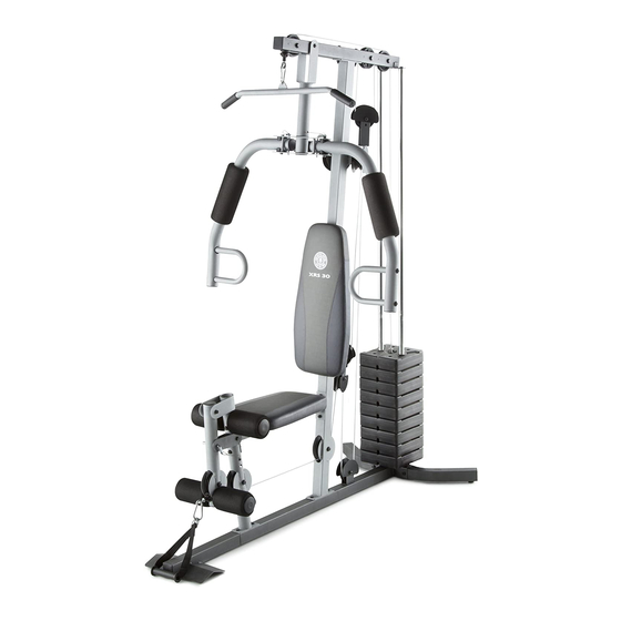
USERʼS MANUAL
Model No. 30321.0
Serial No.
Write the serial number in the
space above for future reference.
Serial Number Decal (under seat)
QUESTIONS?
If you have questions, or if parts
are damaged or missing, PLEASE
CONTACT OUR CUSTOMER
SERVICE DEPARTMENT
DIRECTLY.
1-888-936-4266
CALL TOLL-FREE:
Mon.–Fri., 8:00 until 17:00 ET
(excluding holidays)
OR E-MAIL US:
customerservice@iconcanada.ca
CAUTION
Read all precautions and instruc-
tions in this manual before using
this equipment. Keep this manu-
al for future reference.
www.workoutwarehouse.com
Advertisement
Table of Contents

Related Manuals for Gold's Gym XR45


Summary of Contents for Gold's Gym XR45
- Page 1 USERʼS MANUAL Model No. 30321.0 Serial No. Write the serial number in the space above for future reference. Serial Number Decal (under seat) QUESTIONS? If you have questions, or if parts are damaged or missing, PLEASE CONTACT OUR CUSTOMER SERVICE DEPARTMENT DIRECTLY.
-
Page 2: Table Of Contents
Apply the decal in the location shown. Note: The decal(s) may not be shown at actual size. GOLD'S GYM is a registered trademark of Gold's Gym International, Inc. This product is manufactured and distributed under license from Gold's Gym International, Inc. -
Page 3: Important Precautions
IMPORTANT PRECAUTIONS WARNING: To reduce the risk of serious injury, read all important precautions and instructions in this manual and all warnings on your weight system before using your weight sys- tem. ICON assumes no responsibility for personal injury or property damage sustained by or through the use of this product. -
Page 4: Before You Begin
BEFORE YOU BEGIN Thank you for selecting the versatile GOLDʼS GYM reading this manual, please see the front cover of this ® XR 45 weight system. The weight system offers a manual. To help us assist you, note the product model selection of weight stations designed to develop every number and serial number before contacting us. -
Page 5: Part Identification Chart
PART IDENTIFICATION CHART Refer to the drawings below to identify small parts required for assembly. The number in parentheses by each drawing is the key number of the part, from the PART LIST near the end of this manual. Note: If a part is not in the parts bag, check to see if it has been preattached. -
Page 6: Assembly
ASSEMBLY To make assembly easier, carefully read the • The following tools (not included) may be required following information and instructions: for assembly: two adjustable wrenches • Assembly requires two persons. one rubber mallet • Because of its weight and size, the weight system should be assembled in the location where it will one standard screwdriver be used. -
Page 7: Frame Assembly
Frame Assembly Holes IMPORTANT: To make assembly easier, read the assembly tips on page 6. Insert the Front Base (94) into the Base (1). Then, insert two M8 x 63mm Carriage Bolts (87) up into the indicated holes in the Base. Note: It may be helpful to place a piece of tape over the bolt heads to hold them in place. - Page 8 3. Attach the Front Leg (7) to the Base (1) and to the Front Base (94) with two M8 x 20mm Screws (96). Do not tighten the Screws yet. Attach the Leg Bumper (60) to the Front Leg (7) with an M4 x 20mm Self-tapping Screw (69) and an M4 Washer (33).
- Page 9 5. Slide the two Weight Bumpers (27) onto the Lower Weight Guides (25). Grease Orient seven Weights (22) so that the pin holes are on the bottom as shown. Slide the Weights onto the Lower Weight Guides (25). Insert the Weight Tube Cap (23) into the Weight Tube (24).
- Page 10 7. Attach the Left Cap (19) and the Right Cap (20) to the Lower Shroud (90) with two M5 x 20mm Self-tapping Screws (64) and two M5 Washers (72). Do not tighten the Self-tapping Screws yet. Attach the Top Cap (18) to the Upper Shroud (17) with two M6 x 16mm Screws (62), four M6 Washers (82), and two M6 Locknuts (78).
-
Page 11: Tapping
8. Attach the Upper Shroud (17) to the Top Frame (4) with two M6 x 16mm Screws (62) and two M6 Washers (82). Do not tighten the Screws yet. Attach the Lower Shroud (90) to the brackets on the Stabilizer (2) with two M6 x 16mm Screws (62) and two M6 Washers (82). - Page 12 10. Apply grease to an M10 x 77mm Bolt (79). Attach the Pivot Frame (5) to the Top Frame (4) with the M10 x 77mm Bolt (79) and an M10 Locknut (56). Do not overtighten the Locknut; the Pivot Frame must pivot easily. Attach the two Arm Pins (40) to the Pivot Frame Holes (5) with two M4 x 20mm Self-tapping Screws...
-
Page 13: Cable Assembly
12. Apply grease to an M10 x 85mm Bolt (67) and to two Arm Bushings (44). Attach the Right Arm (9) to the Pivot Frame (5) Grease with the M10 x 85mm Bolt (67), two M10 Washers (57), the two Arm Bushings (44), and an M10 Locknut (56). -
Page 14: Large
14. Route the Arm Cable (54) over a “V”-pulley (46). Attach the “V”-pulley (46), a Large Cable Trap (50), two Full Finger Guards (41), and an M10 Washer (57) to the Upper Upright (3) with an M10 x 63mm Bolt (75) and an M10 Locknut (56). 57 46 Make sure that the Large Cable Trap is orient- ed to hold the Arm Cable (54) in the groove of... - Page 15 17. Apply grease to an M8 x 22mm Shoulder Bolt (65). Attach the Arm Cable (54) to the indicated Cable Pivot (39) with the M8 x 22mm Shoulder Bolt (65) Grease and an M8 Locknut (58). 18. See the CABLE DIAGRAM on page 25 and identify the Low Cable (53).
- Page 16 20. Route the Low Cable (53) under a 90mm Pulley (48) and through the Lower Upright (93). Attach the 90mm Pulley (48) inside the Lower Upright (93) with an M10 x 67mm Bolt (71), two M10 Washers (57), two 12mm Spacers (52), and an M10 Locknut (56).
- Page 17 23. Attach the Low Cable (53) to the “U”-bracket (45) with an M8 Washer (59) and an M8 Locknut (58). See the inset drawing. Do not overtighten the M8 Locknut (58); it should be threaded onto the end of the Low Cable (53) so that only two threads are showing above the Locknut.
- Page 18 26. Wrap the High Cable (55) under a 90mm Pulley (48). Attach the 90mm Pulley (48), a Cable Trap (51), and two Half Finger Guards (43) at the upper hole in the “U”-bracket (45) with an M10 x 51mm Bolt (66) and an M10 Locknut (56). Make sure that the Cable Trap is oriented to hold the High Cable (55) in the groove of the Pulley and that the Half Finger Guards are on the...
- Page 19 29. Note: For clarity, the Shrouds are not shown in this step. Thread an M12 Nut (84) as far as possible onto the High Cable (55). Then, place a Large Washer (85) on top of the Weight Tube (24). Tighten the High Cable (55) into the Weight Tube (24) until all the slack is removed from the cables.
- Page 20 32. Attach the Lock Plate (73) to the Front Leg (7) with an M10 x 70mm Bolt (86), an M10 Washer (57), and an M10 Locknut (56). Do not overtight- en the Locknut; the Lock Plate must pivot easily. 56 57 Attach the Leg Lever Pin (38) to the Front Leg (7) with an M4 x 20mm Self-tapping Screw (69).
- Page 21 34. Attach the Curl Pad (14) to the Curl Post (13) with two M6 x 16mm Screws (62). 35. Make sure that all parts are properly tightened. The use of the remaining parts will be explained in ADJUST- MENT, beginning on page 22. Before using the weight system, pull each cable a few times to make sure that the cables move smoothly around the pulleys.
-
Page 22: Adjustment
ADJUSTMENT This section explains how to adjust the weight system. See the EXERCISE GUIDELINES on page 27 for impor- tant information about how to get the most benefit from your exercise program. Also, refer to the accompanying exercise guide to see the correct form for each exercise. Make sure that all parts are properly tightened each time the weight system is used. - Page 23 USING THE LOCK LEVER When using the low pulley station, engage the Leg Lever Pin (38) into the Leg Lever (8) and the Lock Plate (73). CONVERTING THE ARMS To use the Arms (9, 10) as butterfly arms, insert the Arm Pins (40) into the holes in the Upright (3) and the Pivot Frame (5) as shown.
-
Page 24: Weight Resistance Chart
LOCKING THE WEIGHT STACK To lock the weight stack, insert the Lock Pin (89) through a Lower Weight Guide (25), and secure the Lock (88) on the Lock Pin. WEIGHT RESISTANCE CHART The chart below shows the approximate weight resistance at each exercise station. The numbers in the left col- umn refer to the 12.5-lb. -
Page 25: Cable Diagram
CABLE DIAGRAM The diagram below shows the proper routing of the cables. The numbers in each drawing show the proper route of that cable. Use the diagram to make sure that the cables, cable traps, and finger guards are assembled cor- rectly. -
Page 26: Maintenance
MAINTENANCE Make sure all parts are properly tightened each time the weight system is used. Replace any worn parts imme- diately. The weight system can be cleaned with a damp cloth and a mild, non-abrasive detergent; do not use solvents to clean the weight system. TIGHTENING THE CABLES Woven cable, the type of cable used on the weight system, can stretch slightly when it is first used. -
Page 27: Exercise Guidelines
EXERCISE GUIDELINES FOUR TYPES OF STRENGTH WORKOUTS workout, and the numbers of repetitions and sets to complete. Progress at your own pace and be sensitive Note: A “repetition” is one complete cycle of an exer- to your bodyʼs signals. Follow each strength workout cise, such as one sit-up. - Page 28 EXERCISE LOG Make copies of this page, and use the copies to schedule and record your strength and aerobic workouts. Scheduling and recording your workouts will help you to make exercise a regular and enjoyable part of your life. Strength Exercise Lbs.
-
Page 29: Part List
PART LIST—Model No. 30321.0 R0809A Key No. Qty. Description Key No. Qty. Description Base 12mm Spacer Stabilizer Low Cable Upper Upright Arm Cable Top Frame High Cable Pivot Frame M10 Locknut Seat Frame M10 Washer Front Leg M8 Locknut Leg Lever M8 Washer Right Arm Leg Bumper... -
Page 30: Exploded Drawing
EXPLODED DRAWING A—Model No. 30321.0 R0809A 56 57 48 96... - Page 31 EXPLODED DRAWING B—Model No. 30321.0 R0809A 41 57 41 75...
-
Page 32: Ordering Replacement Parts
ORDERING REPLACEMENT PARTS To order replacement parts, please see the front cover of this manual. To help us assist you, be prepared to provide the following information when contacting us: • the model number and serial number of the product (see the front cover of this manual) •...
Need help?
Do you have a question about the XR45 and is the answer not in the manual?
Questions and answers
I need help to set it up
To set up the Gold's Gym XR45:
1. Insert a Small Foam Pad (28) onto each end of the Leg Lever (8).
2. Press a Pad Cap (34) into each Small Foam Pad.
3. Attach the Curl Pad (14) to the Curl Post (13) using two M6 x 16mm Screws (62).
4. Ensure all parts are properly tightened.
5. Pull each cable a few times to check smooth movement around pulleys.
6. If cables do not move smoothly, correct the problem before use.
7. Check for slack in the cables. If there is slack, tighten them.
Refer to the cable diagram and maintenance section for proper cable routing and adjustments.
This answer is automatically generated
how much does one weight bar - weigh in kilos in the