Table of Contents
Advertisement
Model No. GGSY69320
Serial No.
Write the serial number in the
space above for future reference.
Serial Number Decal (Under Seat)
QUESTIONS?
As a manufacturer, we are com-
mitted to providing complete
customer satisfaction. If you
have questions, or if there are
missing or damaged parts, we
will guarantee complete satis-
faction through direct assis-
tance from our factory.
TO AVOID DELAYS, PLEASE
CALL DIRECT TO OUR TOLL-
FREE CUSTOMER HOT LINE.
The trained technicians on our
customer hot line will provide
immediate assistance, free of
charge.
CUSTOMER HOT LINE:
1-800-999-3756
Mon.–Fri., 6 a.m.–6 p.m. MST
CAUTION
Read all precautions and instruc-
tions in this manual before using
this equipment. Save this manual
for future reference.
USER'S MANUAL
Advertisement
Table of Contents

Related Manuals for Gold's Gym XRT 75 GGSY69320


Summary of Contents for Gold's Gym XRT 75 GGSY69320
- Page 1 Model No. GGSY69320 Serial No. Write the serial number in the space above for future reference. Serial Number Decal (Under Seat) QUESTIONS? As a manufacturer, we are com- mitted to providing complete customer satisfaction. If you have questions, or if there are missing or damaged parts, we will guarantee complete satis- faction through direct assis-...
-
Page 2: Table Of Contents
Decal 1 GOLD'S GYM is a registered trademark of Gold's Gym International, Inc. This product is manufactured and distributed under license from Gold's Gym Merchandising, Inc. Decal 1 Decal 2* Decal 2... -
Page 3: Important Precautions
IMPORTANT PRECAUTIONS WARNING: To reduce the risk of serious injury, read the following important precautions before using the weight system. 1. Read all instructions in this manual and in the accompanying literature before using the weight system. 2. It is the responsibility of the owner to ensure that all users of the weight system are ade- quately informed of all precautions. -
Page 4: Before You Begin
BEFORE YOU BEGIN Thank you for selecting the versatile GOLD’S GYM XRT 75 weight system. The weight system offers a selection of weight stations designed to develop every major muscle group of the body. Whether your goal is to tone your body, build dramatic muscle size and strength, or improve your cardiovascular system, the weight system will help you to achieve the specific results you want. -
Page 5: Assembly
ASSEMBLY Make Assembly Easier for Yourself Everything in this manual is designed to ensure that the weight system can be assem- bled successfully by anyone. Before begin- ning assembly, make sure to read the information on this page. This brief intro- duction will save you much more time than it takes to read it. -
Page 6: Frame Assembly
Frame Assembly Before beginning assembly, make sure you understand the information in the box on page 5. Locate and open the parts bags labeled “FRAME ASSEMBLY 1” and “FRAME ASSEM- BLY 2.” Press four 50mm Square Inner Caps (105) into the Rear Stabilizer (53) and the Long Base (120). - Page 7 4. Press two 25mm x 50mm Round Outer Caps (113) onto the bars on the VKR Upright (5). Attach the VKR Upright (5) to the Long Base (120) with the two indicated M10 x 65mm Carriage Bolts (110) and two M10 Nylon Locknuts (87).
- Page 8 6. Attach the Butterfly Upright (3) to the Short Base (2) with the two indicated M10 x 65mm Carriage Bolts (110) and two M10 Nylon Locknuts (87). Do not tighten the Locknuts yet. Attach the Seat Leg (9) to the Short Base (2) with the two indicated M10 x 65mm Carriage Bolts (110) and two M10 Nylon Locknuts (87).
- Page 9 8. Press three 50mm x 75mm Inner Caps (58) into the Butterfly Top Frame (7). Attach the Butterfly Top Frame (7) to the Butterfly Upright (3) with two M10 x 95mm Bolts (92), two M10 Washers (91), and two M10 Nylon Locknuts (87).
-
Page 10: Arm Assembly
10. Attach the Left Weight Guides (64) to the Short Base (2) with an M10 x 155mm Bolt (95), two M10 Washers (91), and an M10 Nylon Locknut (87). Slide two Weight Bumpers (49) onto the Left Weight Guides (64). Slide the Bottom Weight (1) onto the Guides. - Page 11 13. Attach the Left and Right VKR Arms (30, 31) to the VKR Upright (5) with two M10 x 75mm Bolts (101) and two M10 Nylon Locknuts (87). 14. Press two 40mm x 50mm Inner Caps (21) into the Dip Assist Frame (127). Lubricate an M10 x 207mm Bolt (61) with grease.
- Page 12 16. Press two 40mm x 50mm Inner Caps (21) into the Dip Assist Arm (128). Attach a Knee Rest Bumper (123) to the Dip Assist Arm with an M4 x 20mm Self-tapping Screw (14). Attach the Dip Assist Arm (128) to the Dip Assist Frame (127) with two M10 x 65mm Bolts (18) and two M10 Nylon Locknuts (87).
- Page 13 19. Attach the tethers on the two “L”-pins w/Tethers (60) to the Butterfly Frame (47) with an M4 x 20mm Self-tapping Screw (14). Lubricate an M10 x 80mm Button Head Bolt (104) and both sides of two Plastic Washers (56) with grease.
-
Page 14: Cable Assembly
Cable Assembly IMPORTANT: Refer to the CABLE DIAGRAMS on page 32 for help identifying the cables. Do not overtighten the bolts and nuts attach- ing the pulleys; the pulleys must be able to turn freely. Open the parts bag labeled “CABLE ASSEM- BLY.”... - Page 15 28. Wrap the Dip Cable (74) over a 90mm Pulley (78). Attach the Pulley to the Top Frame (6) with an M10 x 45mm Bolt (93) and an M10 Nylon Locknut (87). 29. Wrap the Dip Cable (74) over a 90mm Pulley (78).
- Page 16 32. Wrap the Dip Cable (74) over a 90mm Pulley (78). Attach the Pulley to the second bracket on the right side of the Butterfly Top Frame (7) with an M10 x 45mm Bolt (93) and an M10 Nylon Locknut (87). 33.
- Page 17 36. Wrap the Squat Cable (73) over a 90mm Pulley (78). Attach the Pulley to the Top Frame (6) with an M10 x 45mm Bolt (93) and an M10 Nylon Locknut (87). 37. Wrap the Squat Cable (73) under a 90mm Pulley (78).
- Page 18 41. Wrap the Butterfly Cable (69) under a 90mm Pulley (78). Attach the Pulley to the Double “U”- bracket (62) with an M10 x 45mm Bolt (93) and an M10 Nylon Locknut (87). 42. Wrap the Butterfly Cable (69) over a “V”-pulley (55).
- Page 19 46. Route the Leg Lever Cable (75) under a 115mm Pulley (119). Attach the Pulley and a Large Cable Trap (121) to the indicated side of the Butterfly Upright (3) with an M10 x 95mm Bolt (92), an M10 Washer (91), and an M10 Nylon Locknut (87).
- Page 20 51. Wrap the Squat Low Cable (72) over a 90mm Pulley (78). Attach the Pulley and a Cable Trap (68) between the second set of holes from the bottom of the indicated pair of Pulley Plates (63) with an M10 x 50mm Bolt (100) and an M10 Nylon Locknut (87).
- Page 21 56. Attach the Squat Low Cable (72) to the other Small “U”-bracket (106) with an M8 Washer (90) and an M8 Nylon Locknut (71). Do not com- pletely tighten the Locknut; it should be tight- ened so that only two threads of the Cable show past the Locknut, as shown in the inset drawing.
- Page 22 61. Wrap the Lat Cable (88) over a 90mm Pulley (78). Attach the Pulley and a Cable Trap (68) between the indicated pair of Pulley Plates (63) at the second set of holes from the bottom with an M10 x 50mm Bolt (100) and an M10 Nylon Locknut (87).
- Page 23 66. Wrap the Fly Cable (85) over a 90mm Pulley (78). Attach the Pulley and a Cable Trap (68) between the lower set of holes in the “U”-bracket (59) with an M10 x 50mm Bolt (100) and an M10 Nylon Locknut (87).
-
Page 24: Seat Assembly
Seat Assembly 71. Locate and open the parts bag labeled “SEAT ASSEMBLY.” Attach the Dip Assist Pad (129) to the Dip Assist Arm (128) with four M6 x 63mm Bolts (34) and four M6 Washers (97). Note: The Dip Assist Arm is shown removed for clarity. - Page 25 75. Attach the Squat Arm (32) to the Squat Bracket (37) with two M10 x 70mm Carriage Bolts (107), two M10 Washers (91), and two M10 Nylon Locknuts (87). Do not tighten the Locknuts yet. Finish attaching the Squat Arm (32) to the Squat Bracket (37) with two M10 x 65mm Carriage Bolts (110) and two M10 Nylon Locknuts (87).
- Page 26 78. Insert the Pad Tube (23) into the square hole in the Seat Leg (9). Slide the two Knee Pads (19) onto the Pad Tube as shown. Press the two Knee Pad Caps (109) into the ends of the Pad Tube. 79.
-
Page 27: Adjustments
ADJUSTMENTS This section explains how to adjust the weight system. See the EXERCISE GUIDELINES on page 34 for important information about how to get the most benefit from your exercise program. Also, refer to the accompanying exercise guide to see the correct form for each exercise. IMPORTANT: When attaching the lat bar, row bar, or handle, make sure that the attachments are in the correct starting position for the exercise to be performed. - Page 28 CHANGING THE WEIGHT SETTING To change the setting of a weight stack, insert a Weight Pin (50) under the desired Weight (44). Insert the Weight Pin so that the bent end touches the weight stack. Turn the bent end down. To use the Bottom Weight (1) with the squat station or the low pulley station, insert the Weight Pin (50) under the Bottom Weight.
- Page 29 ADJUSTING THE SQUAT KNEE REST To use the Squat Knee Rest (41), pivot it down to the position shown and insert the Pin w/Tether (112) into the holes in the Squat Knee Rest and the Long Base (120). When the Squat Knee Rest (41) is not in use, pivot it up to a vertical position and then insert the Pin w/Tether (112) into the hole in the Long Base (120).
-
Page 30: Weight Resistance Chart
WEIGHT RESISTANCE CHART The chart below shows the approximate weight resistance at each exercise station. “Left Top” and “Right Top” refer to the 6 lb. top weights. “Bottom” refers to the 10.5 lb. bottom weight. The other numbers refer to the 12.5 lb. -
Page 31: Troubleshooting
TROUBLESHOOTING Make sure all parts are properly tightened each time the weight system is used. Replace any worn parts immedi- ately. The weight system can be cleaned using a damp cloth and mild non-abrasive detergent. Do not use solvents. TIGHTENING THE CABLES Woven cable, the type of cable used on the weight system, can stretch slightly when it is first used. -
Page 32: Cable Diagrams
CABLE DIAGRAMS The cable diagrams show the proper routing of the Butterfly Cable (69), the Squat Low Cable (72), the Squat Cable (73), the Dip Cable (74), the Leg Lever Cable (75), the Fly Cable (72), and the Lat Cable (88). Use the diagrams to make sure that the cables and the cable traps have been assembled correctly. - Page 33 Butterfly Cable (69) Length: 58 inches Leg Lever Cable (75) Length: 92 inches Fly Cable (85) Length: 145 inches Plate Set A Dip Cable (74) Length: 320 inches Plate Set C Plate Set C...
-
Page 34: Exercise Guidelines
EXERCISE GUIDELINES THE FOUR BASIC TYPES OF WORKOUTS Muscle Building To increase the size and strength of your muscles, push them close to their maximum capacity. Your mus- cles will continually adapt and grow as you progres- sively increase the intensity of your exercise. You can adjust the intensity level of an individual exercise in two ways: •... -
Page 35: Cooling Down
Rest for a short period of time after each set. The ideal resting periods are: • Rest for three minutes after each set for a muscle building workout. • Rest for one minute after each set for a toning work- out. -
Page 36: Part Identification Chart
PART IDENTIFICATION CHART— Refer to the drawings below to identify small parts used in assembly. The number in parentheses by each draw- ing is the key number of the part, from the PART LIST in the center of this manual. Note: Some small parts may have been pre-attached. - Page 37 M6 x 63mm Bolt (34) M10 x 57mm Bolt (98) M10 x 50mm Bolt (100) M10 x 45mm Bolt (93) M8 x 45mm Bolt (108) M6 x 35mm Screw (99) M8 x 20mm Shoulder Bolt (103) M8 x 20mm Button Head Screw (51) M4 x 20mm Self-tapping Screw (14) M6 x 16mm Screw (114) M10 x 65mm Bolt (18)
- Page 38 REMOVE THIS PART IDENTIFICATION CHART AND PART LIST BEFORE BEGINNING ASSEMBLY. SAVE THIS PART IDENTIFICATION CHART AND PART LIST FOR FUTURE REFERENCE. 20mm x 40mm Inner Cap (116) 25mm x 40mm Inner Cap (117) 40mm x 50mm Inner Cap (21) 50mm Square Inner Cap (105) 25mm Round Inner Cap (29)
- Page 39 PART LIST—Model No. GGSY69320 No. Qty. Description Bottom Weight Short Base Butterfly Upright Squat Upright VKR Upright Top Frame Butterfly Top Frame Seat Frame Seat Leg Leg Lever Seat Bracket Curl Frame Backrest Bracket M4 x 20mm Self-tap- ping Screw Butterfly Backrest Seat Curl Pad...
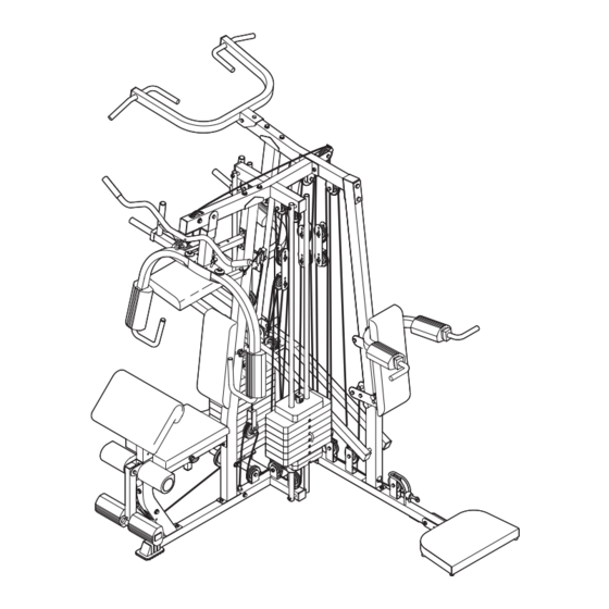
- Page 40 EXPLODED DRAWING—Model No. GGSY69320 R0303A...
- Page 41 EXPLODED DRAWING—Model No. GGSY69320 R0303A...
-
Page 42: Ordering Replacement Parts
ORDERING REPLACEMENT PARTS To order replacement parts, simply call our Customer Service Department toll-free at 1-800-999-3756, Monday through Friday, 6 a.m. until 6 p.m. Mountain Time (excluding holidays). To help us assist you, please be pre- pared to give the following information: 1.
Need help?
Do you have a question about the XRT 75 GGSY69320 and is the answer not in the manual?
Questions and answers