Table of Contents
Advertisement
Quick Links
Advertisement
Table of Contents

Related Manuals for NEC DX2000


Summary of Contents for NEC DX2000
- Page 1 User’s Guide NEC Scalable Modular Server DX2000 Chapter 1 General Description Chapter 2 Installation and Connection Chapter 3 Setup Chapter 4 NW Switch Module Chapter 5 Replacing Modules Chapter 6 Appendix February 2016 © NEC Corporation 2016...
-
Page 2: Documents Provided With This Product
Description of installation and connection as the preparation before using Connection this server Chapter 3: Setup Server module BIOS configurations and summary of DX2000 Utility Disk Chapter 4 NW Switch Features supported by internal switch module, how to setup switches,... - Page 3 Installing the server on the rack and removing it from the rack ....... 44 Preparations and connecting peripheral devices .................... 54 Chapter 3 Setup ............................... 57 Turning on the Server ............................. 58 AC ON of server ......................... 58 Checking LEDs .......................... 59 Scalable Modular Server DX2000 User’s Guide...
- Page 4 Installing OS ..............................77 Turning Off the Server ............................ 78 DX2000 Utility Disk ............................79 Features of DX2000 Utility Disk ....................79 Chapter 4 NW Switch Modules ........................80 Outline of NW Switch Modules ........................81 Accessing NW Switch Modules ........................82 Setting NW Switch Modules..........................
- Page 5 Contents Block Diagram of This Server ........................103 Installing the Server on a Non-NEC Rack ..................... 104 Requirements ........................... 104 Revision Record ............................106 Scalable Modular Server DX2000 User’s Guide...
-
Page 6: Notations Used In This Document
Term indicating a degree of danger attention WARNING Use only the specified outlet Use a grounded outlet with the specified voltage. Use of an improper power source may cause a fire or a power leak. Scalable Modular Server DX2000 User’s Guide... -
Page 7: Notations Used In The Text
Notations and abbreviations used in the text This server described in this document means the main unit. Abbreviation described in the text is as follows. Notation, Name abbreviation Chassis Sensor Card NW Switch Network Switch Scalable Modular Server DX2000 User’s Guide... -
Page 8: Trademarks
Adobe Systems Incorporated. PCI Express is a trademark of Peripheral Component Interconnect Special Interest Group. All other product, brand, or trade names used in this publication are the trademarks or registered trademarks of their respective trademark owners. Scalable Modular Server DX2000 User’s Guide... -
Page 9: License Notification
BSD License which accompanies this distribution. The full text of the license may be found at http://opensource.org/licenses/bsd-license.php THE PROGRAM IS DISTRIBUTED UNDER THE BSD LICENSE ON AN "AS IS" BASIS, WITHOUT WARRANTIES OR REPRESENTATIONS OF ANY KIND, EITHER EXPRESS OR IMPLIED. Scalable Modular Server DX2000 User’s Guide... - Page 10 1. Redistributions of source code must retain the above copyright notice, this list of conditions and the following disclaimer. 2. Redistributions in binary form must reproduce the above copyright notice, this list of conditions and the following disclaimer in the documentation and/or other materials provided with the distribution. Scalable Modular Server DX2000 User’s Guide...
- Page 11 BUSINESS INTERRUPTION) HOWEVER CAUSED AND ON ANY THEORY OF LIABILITY, WHETHER IN CONTRACT, STRICT LIABILITY, OR TORT (INCLUDING NEGLIGENCE OR OTHERWISE) ARISING IN ANY WAY OUT OF THE USE OF THIS SOFTWARE, EVEN IF ADVISED OF THE POSSIBILITY OF SUCH DAMAGE. Scalable Modular Server DX2000 User’s Guide...
- Page 12 License http://opensource.apple.com/source/network_cmds BSD-style Copyright (C) 1995, 1996, 1997, and /network_cmds-328/ping6.tproj/md5.h 1998 WIDE Project http://opensource.apple.com/source/network_cmds /network_cmds-328/ping6.tproj/md5.c SHA2 http://www.aarongifford.com/computers/sha2-1.0.zip BSD-style Copyright (c) 2000-2001, Aaron D. Gifford stdint.h http://msinttypes.googlecode.com/svn/trunk/stdint.h BSD-style Copyright (c) 2006-2008 Alexander Chemeris Scalable Modular Server DX2000 User’s Guide...
-
Page 13: Warnings And Additions To This Document
The contents of this document may change without prior notice. Do not make copies or alter the document content without permission from NEC Corporation. Every effort has been made to ensure the completeness of this document. However, if you have any concerns, or discover errors or omissions, please contact your retailer. -
Page 14: Warning Labels
Warning label are attached on or near the components with potential hazards (This label is either attached or printed on the component.) to draw attention from users to potential hazards involved in handling the server. (Do not remove or black out this label and keep it clean). Scalable Modular Server DX2000 User’s Guide... -
Page 15: Handling Precautions (For Proper Operations)
Reference: Time effective at avoiding condensation in winter (more than 10°C differences between the room temperature and atmospheric temperature) Disk devices: Approximately 2 to 3 hours Scalable Modular Server DX2000 User’s Guide... - Page 16 Keeping your equipment clean is important not only for the appearance but also for functional and safety reasons. A dusty monitor makes it difficult to see the display contents, so clean it regularly. Take rest breaks When you feel tired, take a break. Light exercise is also recommended. Scalable Modular Server DX2000 User’s Guide...
-
Page 17: Chapter 1 General Description
This chapter introduces the features of this server and the name of each part. 1. Introduction 2. Standard Features This section describes the server’s features and the server management. 3. Names and Functions of Parts This section describes the name of each part contained in this server. Scalable Modular Server DX2000 User’s Guide... -
Page 18: Introduction
This high performance server is powered by the latest microprocessor "Intel Xeon processor". NEC’s latest technology and architectures realize high-power and high-speed operation that cannot be matched by existing servers. The server is designed with consideration of not only the density and reliability but also expandability, which enables you to use it as a network server. -
Page 19: Standard Features
Internal voltage monitoring feature • Redundant power supply unit (depending on the configuration) • BIOS password feature • Redundant fan Management features • CSC module that manages modules inside the chassis • Power supply monitoring Scalable Modular Server DX2000 User’s Guide... - Page 20 Maintenance features • A failed server module can be replaced while other server modules are running Block diagram • See the block diagram in the appendix for the linkage between modules incorporated in this server. Scalable Modular Server DX2000 User’s Guide...
-
Page 21: Management Features
Displaying SEL information sensor Displaying sensor information lan alert print Checking the alert receiver chassis identify<interval> Turn on UID lamp default setting of <interval> is 15 seconds. Setting is “0”, UID lamp turn off. Scalable Modular Server DX2000 User’s Guide... -
Page 22: Server Modules
Session SOL connection function SEL (System Event Log) Indicates SEL information. Sensor Indicates sensor information. Alert receiver Used to specify the alert receivers. BIOS information Information such as BIOS version, boot priority, IDE mode Scalable Modular Server DX2000 User’s Guide... -
Page 23: Names And Functions Of Parts
Chapter1 General Description 3. Names and Functions of Parts Names and Functions of Parts This section describes the names of the server parts. External View Top cover Front panel Scalable Modular Server DX2000 User’s Guide... -
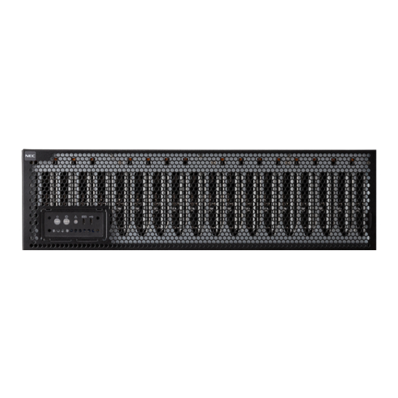
Page 24: Front View
Pressing the switch once turns on the UID LED and pressing again turns off the LED. Commands from software also cause the UID LED to turn on. (3) STATUS LED This LED indicates the server status. Scalable Modular Server DX2000 User’s Guide... - Page 25 On (amber) A PSU alarm was detected. A temperature alarm was detected. A CPU error has occurred. Abnormal CPU temperature is detected. Abnormal voltage in the module is detected. A fan error was detected. Scalable Modular Server DX2000 User’s Guide...
-
Page 26: Rear View
(4)-2 NW switch module 2 side (2) AC inlet Socket to connect the power cord Switch modules with 8 40Gbps compatible QSFP module slots CSC modules Modules to monitor sensors of the main unit Scalable Modular Server DX2000 User’s Guide... -
Page 27: Internal View
3rd row 37 to 44 -1 POWER1 * The number of installable modules varies depending on -2 POWER2 modules implemented. -3 POWER3 (2) NW switch modules -1 NW switch 1 -2 NW switch 2 Scalable Modular Server DX2000 User’s Guide... -
Page 28: Unit Of Servers
Server 21 Server module (ID = 21) Server 3 Server module (ID = 03) Server 44 Server module (ID = 44) Server 36 Server module (ID = 36) Server 18 Server module (ID = 18) Scalable Modular Server DX2000 User’s Guide... - Page 29 10G LAN module (ID=44) 10G LAN module (ID=18) Server module (ID=27) Server 18 10G LAN module (ID=28) Server module (ID=29) Server 19 10G LAN module (ID=30) : : Server module (ID=35) Server 22 10G LAN module (ID=36) Scalable Modular Server DX2000 User’s Guide...
- Page 30 Server module (ID=18) Server 21 PCI-E card (ID=39) : : Server module (ID=26) Server 26 PCI-E card (ID=44) Server 27 Server module (ID=27) Server 28 Server module (ID=28) : : Server module (ID=36) Server 36 Scalable Modular Server DX2000 User’s Guide...
-
Page 31: Server Module
(2) BMC RESET Switch ) Micro USB Connector Exclusively used for maintenance The switch to reset BMC of the server module. Do not use this. The server monitoring function stops until BMC has been initialized after resetting Scalable Modular Server DX2000 User’s Guide... - Page 32 This LED is used to identify a specific module among multiple modules installed in the server. The following table describes each UID LED status and its meaning. UID LED status Description On (blue) The UID switch is on. The UID switch is off. Scalable Modular Server DX2000 User’s Guide...
-
Page 33: Nw Switch Module
A temperature error was detected in the module. A voltage error was detected in the module. RESET Switch The switch to reset the NW switch module. The external network is not available until the completion of initialization. Scalable Modular Server DX2000 User’s Guide... - Page 34 (2) QSFP module slot LINK/ACT LED LINK/ACT LED ofeach QSFP module slot LED to indicate the access status of LAN (3) LAN connector dedicated to management 1000BASE-T/100BASE-TX/10BASE-T support connector Not available as normal LAN Scalable Modular Server DX2000 User’s Guide...
- Page 35 The following table describes each SPEED LED status and its meaning SPEED LED status Description On (amber) The ports are running with the 1000BASE-T interface. On (green) The ports are running with the 100BASE-TX interface. The ports are running with the 10BASE-T interface. Scalable Modular Server DX2000 User’s Guide...
-
Page 36: Csc Module
Lighting in amber CSC modules are being initialized. Server modules are being initialized. A fan error was detected. A temperature error was detected. A voltage error was detected. An error was detected in the mounted module. Scalable Modular Server DX2000 User’s Guide... - Page 37 When the UID switch is turned off CSC RESET Switch The switch to reset CSC The monitoring function of the main unit (for temperature, fan, etc.) stops until the completion of initialization after resetting. Scalable Modular Server DX2000 User’s Guide...
-
Page 38: Power Supply Unit
AC power is supplied. Lock lever Press the lever to unlock it when you pull out the power unit. Handle Press the lock lever (2) and hold this handle to pull out the power unit. Scalable Modular Server DX2000 User’s Guide... -
Page 39: Fan Module
While the fan is running normally, the STATUS LED is off. If the fan fails, the STATUS LED lights amber. The following table describes each STATUS LED status and its meaning. STATUS LED status Description The power is off. The fan is normally running. On (amber) A fan error has occurred. Scalable Modular Server DX2000 User’s Guide... -
Page 40: Chapter 2 Installation And Connection
This chapter describes preparations and connection for using this server. 1. Installation This section describes how to select an installation site appropriate to the server. 2.Preparations and connecting peripheral devices This section describes the connection of this server. Scalable Modular Server DX2000 User’s Guide... -
Page 41: Installation
This section describes how to install the server. Installation This server must be installed on a rack that conforms to EIA standards. For available racks, refer to Chapter 6 (3. Installing the Server on a Non-NEC Rack). 1.1.1 Installing a rack Refer to the manual that comes with your rack for how to install the rack, or consult with your sales representative. - Page 42 If you must install the server close to such equipment, have your maintenance service company separate power cables or install noise filter. • Environment where operation of the server is not guaranteed Scalable Modular Server DX2000 User’s Guide...
-
Page 43: Securing The Maintenance Area
Secure a maintenance area at least 1000mm before and after the rack and 600mm or more on the right and left side to perform maintenance from both sides with the equipment extracted. or more Work area or more or more or more or more Scalable Modular Server DX2000 User’s Guide... -
Page 44: Installing The Server On The Rack And Removing It From The Rack
Air enters the server from the front and exits from the rear. Important The location of the installed device to the rack. Never locate this equipment into the lowest unit of rack. Because the space for cable-arm maintenance is reserved. Scalable Modular Server DX2000 User’s Guide... - Page 45 Chapter 2 Installation and connection 1. Installation Installation This server can be installed on a rack made by NEC or other companies. Install the server on a rack by using the following procedure. • Preparation Before installing the server, check and install the inner and outer rails.
- Page 46 Do not lift the server alone. Three or more workers should perform the operation. • Do not drop. • Do not leave the server being pulled out. • Do not install with the cover removed. • Do not get your fingers caught. Scalable Modular Server DX2000 User’s Guide...
- Page 47 3. Push the server until the inner rails stops halfway. 4. Push the stopper of the left and right inner rails to unlock the middle rail. When you find it unlocked, tuck in the server. Stopper of inner rail Scalable Modular Server DX2000 User’s Guide...
- Page 48 1. Installation 5. Push the server until the right and left rails on the front side are locked. 6. Mount the cable fixing metal fitting. 7. Installing the server on the rack is now complete. Scalable Modular Server DX2000 User’s Guide...
- Page 49 Then, fix cables as shown in the lower right figure. Scalable Modular Server DX2000 User’s Guide...
- Page 50 Before installing the cable, check that the direction of the section C is that shown in the lower left figure. If you find it reverse, change the direction by pressing the button as shown in the lower right figure. Install two cable bands to the cable arm. Scalable Modular Server DX2000 User’s Guide...
- Page 51 4. Sections A and B have been installed. 5. Insert the section C into the slide rail side and push it until it gets locked. 6. Section C has been installed Scalable Modular Server DX2000 User’s Guide...
- Page 52 8. Draw the server slowly and make sure the excessive tension is not applied to the entire cable wiring section. Pay special attention to the installation part of the cable arm. Cable wiring section Scalable Modular Server DX2000 User’s Guide...
- Page 53 Remove it slowly while several persons are supporting the bottom part of the server. Do not apply pressure on the server from top when it is being pulled out. Doing so may cause the server to drop. Scalable Modular Server DX2000 User’s Guide...
-
Page 54: Preparations And Connecting Peripheral Devices
Description about ipmitool is given on the next and the subsequent pages. However, it is described as a use example, and NEC does not assure the support of ipmitool. For details of ipmitool, contact your sales representative. - Page 55 DHCP Server Server for OS install Rear view (10) (11) (14) (8)-b (12) (13) TFTP Server DHCP Server SMNP Manager * This connection image is an example. Connect devices to fit your system environment. Scalable Modular Server DX2000 User’s Guide...
- Page 56 DX2000. (13) SNMP Manager DHCP server setting is required in advance to For receiving a PET alert. allocate an IP address of DX2000 from the DHCP server. (14) Switching Hub (for management) (6) Server for OS install Used to relay the connection between the Use to install OS to each server module.
-
Page 57: Chapter 3 Setup
This section describes how to install OS 8. Turning Off the Server This section describes how to turn off the server. 9. DX2000 Utility Disk This section describes how to use DX2000 Utility Disk. Scalable Modular Server DX2000 User’s Guide... -
Page 58: Turning On The Server
30 seconds to insert the AC cables after the AC cables are removed. Check that the power LED is turned off before connecting the AC cables. Connect AC cables to the three power supply modules. Connect the AC cable. Scalable Modular Server DX2000 User’s Guide... -
Page 59: Checking Leds
The NW switch module starts booting the built-in OS as soon as it starts initialization. It takes about 90 seconds to start booting. After completing booting, network connection is enabled. This server completes preparation for booting. Status LED Lighting in amber ↓ Power status LED Should light up in green. Scalable Modular Server DX2000 User’s Guide... -
Page 60: Preparation Of Network Access
(64bit version Linux). Grant an appropriate owner authority to the copied server management utility so that root users can execute it. Example) To copy DX2000 Utility Disk (CD-ROM) under /mnt to /opt/mng directory of the server management terminal... - Page 61 LAN-SW2 94:DE:80:AB:02:A9 192.168.0.03 CPU Board1 94:DE:80:AB:00:34 192.168.0.11 94:DE:80:AB:03:D2 94:DE:80:AB:03:D3 CPU Board2 94:DE:80:AB:00:35 192.168.0.12 94:DE:80:AB:03:D4 94:DE:80:AB:03:D5 CPU Board3 94:DE:80:AB:00:36 192.168.0.13 94:DE:80:AB:03:D6 94:DE:80:AB:03:D7 CPU Board4 94:DE:80:AB:00:37 192.168.0.14 94:DE:80:AB:03:D8 94:DE:80:AB:03:D9 Example of specifying a MAC address list Scalable Modular Server DX2000 User’s Guide...
-
Page 62: Checking Ip Addresses
[Board type] [MAC of Management LAN] [IP of Management LAN] [MAC of data LAN][ MAC of data LAN] If you cannot check IP addresses of the implemented slots, check the setting and connection of the DHCP server again. Scalable Modular Server DX2000 User’s Guide... -
Page 63: Connection To Csc Modules
The default login user name and the password are as follows. <To control each single server module> User name : Administrator Password : Administrator The following management terminal screen is displayed if the connection is successful. Scalable Modular Server DX2000 User’s Guide... -
Page 64: Setting Csc Module Fw
Set the IP address. (Default is 0.0.0.0.) Host name: Set a host name. Domain name: Set a domain name. Limitation type: Set a permission address/rejection address for access limitation. Set no limitation (Default) for no access limitation. Scalable Modular Server DX2000 User’s Guide... - Page 65 Confirmation password: Enter the same character string as the password. Privilege: Set the authority from the following three types. * Administrator (All operations are available.) * Operator (Operations except setting and FW update are available.) * User (Displaying IPMI information is available.) Scalable Modular Server DX2000 User’s Guide...
- Page 66 Subject option: Set this when you enable Alert. Server: Set this when you enable Alert. (Required) Port: Set this when you enable Alert. (Required) (Default is 25.) Alert level: Set this when you enable Alert. Scalable Modular Server DX2000 User’s Guide...
- Page 67 Set this when you enable Alert. Alert Acknowledge: Set this when you enable Alert. Alert Receiver 1 IP address: Set this when you enable Alert. (Required) Alert Level: Set this when you enable Alert. Scalable Modular Server DX2000 User’s Guide...
- Page 68 Platform Event Filtering: Enable/Disable (Default) ESMPRO Management: Enable/Disable (Default) Authentication key: Set this when you enable Message. Set this when you enable Management from ESMPRO. Redirection (LAN): Set this when you enable Management from ESMPRO. Scalable Modular Server DX2000 User’s Guide...
-
Page 69: Connection To Bmc
2.3. http://BMC_HostPort or https://BMC_HostPort Example: http://192.168.1.1:80 The default login user name and the password are as follows. User name: Administrator Password: Administrator The following management screen is displayed when the connection is successful. Scalable Modular Server DX2000 User’s Guide... -
Page 70: Setting Bmc
When you logged in the BMC management screen, configure various settings as required in the same manner as CSC modules. Connection of RemoteKVM Click the RemoteKVM icon (red) on the bottom of the Web screen to start RemoteKVM. Scalable Modular Server DX2000 User’s Guide... -
Page 71: Setting Required For Using Serial Over Lan (Sol)
#ipmitool -I lanplus -H [IP address] -U [BMC-user] -P [password] sol activate IP-address: BMC IP address of target BMC-user: Administrator Password: Administrator Operation on the management terminal SOL is enabled by default setting. You cannot change setting. Scalable Modular Server DX2000 User’s Guide... -
Page 72: Turning On Dc Of Server Modules
Turn on DC from the Web console screen of BMC of the slot for which DC is turned on. <For IPMI> Turn on DC by sending an IPMI command to BMC of the slot for which DC is turned on. # ipmitool -I lanplus -U Administrator -P Administrator -H <BMC_IP_Address> power on Scalable Modular Server DX2000 User’s Guide... -
Page 73: System Bios Setup (Description Of Setup)
& Exit” menu to exit it To discard the setting, select “Discard Changes and Exit” or “Discard Changes and Power Off” in “Save & Exit” menu to exit it. Tips To restore the default value, select Save & Exit, and then Restore Defaults. The default value may be different from the factory setting. Scalable Modular Server DX2000 User’s Guide... -
Page 74: Description On On-Screen Items And Key Usage
Quit without saving? [Yes] □ <F1> key Press this key to display help information. If you need help using the SETUP, press this key. Press the <Esc> key to go back to the original screen. Scalable Modular Server DX2000 User’s Guide... - Page 75 Load Setup Defaults? [Yes] □ <F4> key If you press this key, the following window appears. If you select Yes, the parameter you configured is saved and SETUP closes. Save configuration and exit? [Yes] Scalable Modular Server DX2000 User’s Guide...
-
Page 76: Cases That Require Configuration
Only if a case applies to any of following cases, use the SETUP utility to change the factory settings of the relevant parameter. Other than cases described below, do not change the settings. A list of SETUP parameters and factory settings are described in Chapter 2 (1. Server Module BIOS) in DX2000 Maintenance Guide. Category... -
Page 77: Installing Os
Chatpter 3 Setup 7. Installing OS Installing OS Install OS on the intended server module. See the installation guide of each OS for installing OS. Scalable Modular Server DX2000 User’s Guide... -
Page 78: Turning Off The Server
DC ON state. Turn off the module in the DC ON state before turning off the AC power.. Turn off peripheral devices. Tips Hibernation feature of Windows Server is not available. Do not set this feature from the shutdown menu. Scalable Modular Server DX2000 User’s Guide... -
Page 79: Dx2000 Utility Disk
Chatpter 3 Setup 9. DX2000 Utility Disk DX2000 Utility Disk The DX2000 Utility Disk helps you to monitor the status of this server and maintain the server. Features of DX2000 Utility Disk The DX2000 Utility Disk provides the following features. -
Page 80: Chapter 4 Nw Switch Modules
This section describes the support function list of NW switch modules. 2. Accessing NW Switch Modules This section introduces documents to be referred in setting up NW switch modules. 3. Setting NW Switch Modules Set NW switch modules. Scalable Modular Server DX2000 User’s Guide... -
Page 81: Outline Of Nw Switch Modules
The management LAN accessed through the maintenance LAN port is defaulted to VLAN. The route for management and that for the data are separated. However, you can change the setting according to your environment. Scalable Modular Server DX2000 User’s Guide... -
Page 82: Accessing Nw Switch Modules
NW switch module obtained in section 2.3. Access by telnet or ssh is supported. (scheduled) See <Document of NW switch modules> for the detail. ・NEC Scalable Modular Server DX2000 NW Switch Command-Line Reference ・NEC Scalable Modular Server DX2000 NW Switch Configuration Guide... -
Page 83: Setting Nw Switch Modules
Setting NW Switch Modules Set NW switch modules. See <Document of NW switch modules> for the detail. ・NEC Scalable Modular Server DX2000 NW Switch Configuration Guide ・NEC Scalable Modular Server DX2000 NW Switch Command-Line Reference Scalable Modular Server DX2000 User’s Guide... -
Page 84: Chapter 5 Replacing Modules
NEC Scalable Modular Server DX2000 Replacing Modules This chapter describes procedures to replace modules in the server. Replacing Internal Modules Describes about replacement procedures and precautions. Scalable Modular Server DX2000 User’s Guide... -
Page 85: Replacing Internal Modules
We recommend that Maintenance service company who is approved by NEC should replace the modules. Use only the modules specified by NEC. You will be charged to repair damages, malfunctions, and failures caused by the use of any devices or cables not specified for use with this server even within the warranty period. -
Page 86: Overview Of Replacing Modules
Refer to Chapter 5 (1.5 Removing the Top Cover). Follow the procedure for the components to be replaced in order. Mount the top cover. Mount the server onto the rack. Refer to Chapter 2 (1.1 installation). This completes replacement of each module. Scalable Modular Server DX2000 User’s Guide... -
Page 87: Identifying The Server By Using The Uid Switch
When the UID lamp of the built-in server module lights up, UID lamps in the front and back of the server stay on even if you press the UID switch of the server. UID switch Scalable Modular Server DX2000 User’s Guide... -
Page 88: Power Supply Unit
Do not remove a power supply unit running normally. Tips In the redundant power configuration (with two power supply units), if one of the power supply units fails, you can replace the faulty power supply unit while the system is on. Scalable Modular Server DX2000 User’s Guide... - Page 89 Press the lever of the power supply unit, hold the handle and pull out the unit slowly. Install the new power supply unit in the reverse order. Firmly insert the power supply unit until the click sound is heard. Scalable Modular Server DX2000 User’s Guide...
-
Page 90: Removing The Top Cover
Loosen the screw on the back of the top cover. Press the lock lever on the right and left sides of the top cover, slide the cover and lift it to remove it. Lock lever Scalable Modular Server DX2000 User’s Guide... -
Page 91: Replacing The Server Module And 10G Lan Module
Important • You must avoid static electricity to work with the procedure below. For details, refer to Handling precautions (for anti-static measures). • Use only a server module authorized by NEC. 1.6.1 Replacement Follow the steps below to replace the server module. - Page 92 Important Backup the configuration of NW switch modules as required. See “DX2000 LAN Switch Configuration Guide” for the backup procedure. It is not recommended that you preferentially activate one side in a redundant configuration of LAN of server modules. When the configuration of NW switch modules is initialized, the initial switch side is enabled.
- Page 93 • Make sure the module is installed in the correct direction. • Be sure to hold the server module only at the ejector or cover. Pay attention not to touch the bottom of the server module (pin section). Scalable Modular Server DX2000 User’s Guide...
- Page 94 – The server module is not inserted correctly in the slot. – All screws are not completely tightened. • You cannot touch the heat sink because it is covered up by the slot cover. Scalable Modular Server DX2000 User’s Guide...
-
Page 95: Nw Switch Modules
Check the location of the NW switch module to be replaced. Ejector POWER LED Handle Remove the LAN cable, QSFP+ modules and the maintenance LAN cable connected to the NW switch module to be replaced. Scalable Modular Server DX2000 User’s Guide... - Page 96 The pull-tab of the QSFP+ module is used for pulling out the module. If you hold the pull-tab to install the module, you may damage the pull-tab. Do not hold the pull-tab to install the module. Scalable Modular Server DX2000 User’s Guide...
-
Page 97: Csc Modules
1. Replacing Internal Modules CSC Modules 1.8.1 Replacement Turn the hand screw fixing the CSC module to pull it out slowly. Hand screw Install the replacement CSC module firmly and tighten the hand screw to fix it. Scalable Modular Server DX2000 User’s Guide... -
Page 98: Replacing A Fan Module
Important • You must avoid static electricity to work with the procedure below. For details, refer to "Handling precautions (for anti-static measures)". • Use only a fan module authorized by NEC. 1.9.1 Replacement Follow the steps below to replace a fan module. - Page 99 Confirm that the orange knob hooks on the fan cage firmly. The fan module starts rotating and the STATUS LED on the fan module lights. Confirm that after a while the STATUS LED on the fan module turns off. Scalable Modular Server DX2000 User’s Guide...
-
Page 100: Chapter 6 Appendix
Block Diagram of This Server This section shows the block diagram of this server. Installing the Server on a Non-NEC Rack This section describes installation of this server on a non-NEC rack. Revision Record Revision history of this document Scalable Modular Server DX2000 User’s Guide... -
Page 101: Specifications
Environmental requirements Operating: 10 to 40C / 20 to 80%, Temperature/Humidity Storage: –10~55C / 20 to 80% (no condensation either when operating or when stored) Main accessories one-touch rack rail, Cable arm, 200V-AC Cable Scalable Modular Server DX2000 User’s Guide... -
Page 102: Dx20A-X Spec
Operating: 10 to 40C / 20 to 80%, Temperature/Humidity Storage: –10~55C / 20 to 80% (no condensation either when operating or when stored) Installed OS – Supported OSs RHEL7.2 Others Hot Swappable Support S0 and S5 state. Scalable Modular Server DX2000 User’s Guide... - Page 103 Environmental requirements Operating: 10 to 40C / 20 to 80%, Temperature/Humidity Storage: –10~55C / 20 to 80% (no condensation either when operating or when stored) Main accessories one-touch rack rail, Cable arm, 200V-AC Cable Scalable Modular Server DX2000 User’s Guide...
-
Page 104: Block Diagram Of This Server
Chapter 6 Appendix 2. Block Diagram of This Server Block Diagram of This Server The figure below shows how modules incorporated in this server are linked. Scalable Modular Server DX2000 User’s Guide... -
Page 105: Installing The Server On A Non-Nec Rack
Described below is a guideline of the propriety, and does not ensure the installation of the server to a non-NEC rack. NEC does not perform any test such as the temperature test and the vibration test on the server installed on a non-NEC rack. Therefore, the server must be installed out on user's responsibility. - Page 106 Chapter 6 Appendix 3. Installing the Server on a Non-NEC Rack Shape of mount angle (same shape on front and rear face) Square hole 9.5 mm sq. (*) 12.7mm 15.875mm 44.45mm (1U) 15.875mm 12.7mm 15.875mm 44.45mm (1U) 15.875mm 450mm or more 465mm (*): Can be a round hole of 7.1 ±0.1 mm.
-
Page 107: Revision Record
Chapter 6 Appendix 4. Revision Record Revision Record Date Issed Description February 2016 Newly created Scalable Modular Server DX2000 User’s Guide... - Page 108 [MEMO]...
- Page 109 [MEMO]...
- Page 110 NEC Micro Modular Server DX2000 User’s Guide February 2016 NEC Corporation 7-1 Shiba 5-Chome, Minato-Ku Tokyo 108-8001, Japan ©NEC Corporation 2016 The contents of this manual may not be copied or altered without the prior written permission of NEC Corporation.
Need help?
Do you have a question about the DX2000 and is the answer not in the manual?
Questions and answers