Table of Contents
Advertisement
Quick Links
DGW-100XR User Manual
Table of Contents
Table of Contents
1. Overview
What is DGW-100XR?
Sample Application
Product Appearance
Main Features
Physical Information
Software
2. System
Status
Call Status
Time
Login Settings
General
Language Settings
Scheduled Reboot
Tools and Information
Reboot Tools
Update Firmware
Upload and Backup Configuration
Restore Configuration
Information
3. T1/E1
General
ISDN-PRI
Advanced: Interface Type
ISDN: Signaling
SS7
Link Set Settings
Link Settings
SS7 Config. File Backup and Restore
MFC/R2
Advanced: Interface Type
MFC/R2: Signaling
4.VOIP
VOIP Endpoints
SIP Endpoints
Main Endpoint Settings
Advanced: Registration Options
Call Settings
Advanced Timer Settings
Advanced: Signaling Settings
IAX2 Endpoint
Advanced SIP Settings
Advertisement
Table of Contents

Related Manuals for OpenVox DGW-1004


Summary of Contents for OpenVox DGW-1004
- Page 1 DGW-100XR User Manual Table of Contents Table of Contents 1. Overview What is DGW-100XR? Sample Application Product Appearance Main Features Physical Information Software 2. System Status Call Status Time Login Settings General Language Settings Scheduled Reboot Tools and Information Reboot Tools Update Firmware Upload and Backup Configuration Restore Configuration...
-
Page 2: Sample Application
What is DGW-100XR? OpenVox T1/E1 Gateway is an open source asterisk-based VoIP Gateway solution for operators and call centers. It is a converged media gateway product. This kind of gateway connects traditional telephone system to IP networks and integrates VoIP PBX with the PSTN seamlessly. -
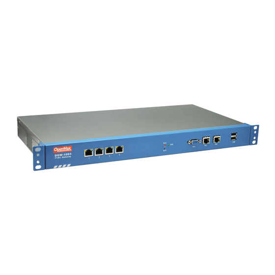
Page 3: Product Appearance
Figure 1-2-1Topological Graph Product Appearance The picture below is appearance of DGW-1004. Figure 1-3-1 Product Appearance Figure 1-3-2 Front Panel Table 1-3-1 Description of Front Panel Interface Function Color Work Status 1 Port 1-Port4 E1/T1 ports. The port numbers are different on different models, from 1 to 4. -
Page 4: Main Features
Network interface 8 USB USB interface Figure 1-3-3 Backup Panel The OpenVox DGW-100X series gateways provides one or two power supply, one power named DGW-100X ,the other is named DGW-100XR, ‘R’ stands for Reduntant. Main Features ® Based on Asterisk ®... - Page 5 LAN port WAN port Software Default IP: 172.16.100.1 Username: admin Password: admin Notice: Log in Figure 1-6-1 LOG IN Interface 2. System Status On the “ System Status ” page, you will find all Interface status, channels status, SIP, IAX2, Routing rules, and Network information.
-
Page 6: Call Status
Figure 2-1-1 System Status Table 2-1-1 Description of System Status Options Definition Interface Show the status of port, include "OK" and ”Down”. "Down" means no trunk line connected; "OK" means the trunk line of port Status is available. Channels Stat Show the Channels status of port, include "Idle". - Page 7 Figure 2-2-1 Verbose of call status Time Table 2-2-1Description of Time Settings Options Definition System Time Your gateway system time. Time Zone The world time zone. Please select the one which is the same or the closest as your city. POSIX TZ String Posix timezone strings.
-
Page 8: Login Settings
Figure 2-2-1 Time Settings You can set your gateway time Sync from NTP or Sync from Client by pressing different buttons. Login Settings Your gateway doesn't have administration role. All you can do here is to reset what new username and password to manage your gateway. And it has all privileges to operate your gateway. -
Page 9: Language Settings
Figure 2-3-1 Login Settings Notice: Whenever you do some changes, do not forget to save your configuration. General Language Settings You can choose different languages for your system. If you want to change language, you can switch “Advanced” on, then “Download” your current language package. -
Page 10: Update Firmware
If use your system frequently, you can set this enable, it can helps system work more efficient. Tools and Information On the “Tools” pages, there are reboot Tools, update Firmware, upload Configuration, backup Configuration and Restore Configuration toolkits. Reboot Tools You can choose system reboot and Asterisk reboot separately. -
Page 11: Restore Configuration
Figure 2-5-3 Upload and Backup Restore Configuration Sometimes there is something wrong with your gateway that you don’t know how to solve it, mostly you will select factory reset. Then you just need to press a button, your gateway will be reset to the factory status. Figure 2-5-4 Factory Reset Information On the “Information”... - Page 12 Local Your local. This will be used for the tone style. Used when in-call indications need to be generated such as ring back, busy, congestion, and other call-oriented inband tone signals. Interface It shows you the current type of port. It has two type:E1 and T1 Type Table 3-1-2 Definition of advanced interface type Options...
- Page 13 Coding Coding method for this interface Line Line build-out represents the length of the cable form the port on this gateway to the next device. Build-out CRC4 Enable cyclic redundancy checking for error checking on line. CRC-4 support is required for all network switches in Europe, but many older switches and PBXs don’t support it.
- Page 14 Figure 3-2-2 ISDN: Signaling Table 3-2-2 Definition of Signaling Options Definition Q.SIG Channel Sets logical or physical channel mapping. In logical channel mapping, channels are mapped to 1-30.In physical channel Mapping mapping, channels are mapped to 1-15,17-31,skipping the number used for the data channel, Default is physical. Enable Caller ID Whether or not to use caller ID PRI Dial Plan for...
- Page 15 Idle Bearer Reset Sets the time in seconds between restart of unused B channels; defaults to ‘never’ Period Display Send Send/receive ISDN display IE options, the display options are a comma separated list of the following options: Block: Do not pass display text data. Name_ initial: Use display text in SETUP/CONNECT messages as the party name.
- Page 16 Link Set Settings Figure 3-3-1 Link Set Settings You can click button as shown below, when there are several link set, only one can be set to the default. Figure 3-3-2 SS7 Link Set Settings Table 3-3-1 Definition of SS7 Link Set Settings options Definition Name...
- Page 17 Link Settings Figure 3-3-3 Link Settings You can click button as shown below. Figure 3-3-4 SS7 Link Settings SS7 Config. File Backup and Restore Figure 3-3-5 Config. File Backup and Restore MFC/R2 Advanced: Interface Type...
- Page 18 Figure 3-4-1 Advanced: Interface Type Table 3-4-1 Definition of Interface Type options Definition Echo Cancellation Whether or not enable echo cancellation on this line RX Gain Whole number -24 to 24 and multiple of 3 Gain for the rx (receive_ into Asterisk) channel. Default:0.0 TX Gain Whole number -24 to 24 and multiple of 3 Gain for the tx (receive_ into Asterisk) channel.
-
Page 19: Sip Endpoints
mfcr2_mfback_timeout MFC/R2 value in milliseconds for the MF timeout mfcr2_metering_pulse_timeout MFC/R2 value in milliseconds for the metering pulse timeout 4.VOIP VOIP Endpoints SIP Endpoints This page shows everything about your SIP, you can see status of each SIP. Figure 4-1-1 SIP Status Main Endpoint Settings You can click button to add a new SIP endpoint, and if you want to modify existed endpoints, you can click... - Page 20 Figure 4-1-3 Endpoint Register with Gateway Also you can choose registration by “This gateway registers with the endpoint”, it’s the same with “None”, except name and password. Figure 4-1-4 This Gateway Register with the Endpoint Table 4-1-1 Definition of SIP Options Options Definition Name...
-
Page 21: Call Settings
Advanced: Registration Options Table 4-1-2 Definition of Registration Options Options Definition Authentication User A username to use only for registration. Register Extension When Gateway registers as a SIP user agent to a SIP proxy (provider), calls from this provider connect to this local extension. - Page 22 Call Setup Timer If a provisional response is not received in this amount of time, the call will auto-congest. Defaults to 64 times the default T1 timer. Session Timers Session-Timers feature operates in the following three modes: originate, Request and run session-timers always; accept, run session-timers only when requested by other UA;...
- Page 23 In some cases,T.38 endpoints will provide a T38FaxMxDatagram value (during T.38 setup) that is based on an incorrect Datagram interpretation of the T.38 recommendation, and result in failures because Asterisk does not believe it can send T.38 packets of a reasonable size to that endpoint (Cisco media gateway are one example of this situation).In these cases, during a T.38 call you will see warring messages on The console/in the logs from the Asterisk UDPTL stack complaining about lack of buffer space to send T.38FaxMaxDatagram value specified by the other end[point, and use a configured value instead.
- Page 24 Figure 4-1-6 Edit IAX Endpoint "9001" Table 4-1-6 Definition of IAX2 Endpoint Options Definition Name A name which is able to read by human. And it’s only used for user’s reference. User name User name the endpoint will use to authenticate with the gateway Password Password the endpoint will use to authenticate with gateway.
- Page 25 Trunk MTU With a large amount of traffic on IAX2 trunk, there is a risk of bad voice quality when allowing the Linux system to handle fragmentation of UDP packets. Depending on the side of each payload, allowing the OS to handle fragmentation may not be very efficient. This setting sets the maximum transmission unit for AIX2 UDP trunking.
- Page 26 Options Definition Local Network Format:192.168.0.0/255.255.0.0 or 172.16.0.0./12. A list of IP address or IP ranges which are located inside a NATed network. This gateway will replace the internal IP address in SIP and SDP messages with the external IP address when a NAT exists between the gateway and other endpoints.
- Page 27 Options Definition Check header tags, character conversion in URIs, and multiline headers for strict SIP compatibility(default is yes) Strict RFC Interpretation Send compact SIP headers Send Compact Headers Allows you to change the username filed in the SDP owner string. This filed MUST NOT contain spaces.
-
Page 28: Codec Settings
If available, match user entry using the 'username' field from the authentication line instead of the 'from' field. Match Auth Username Realm for digest authentication. Realms MUST be globally unique according to RFC 3261. Set this to your host name or domain name. - Page 29 Figure 4-2-1 Codec Settings Advanced IAX2 Settings Table 4-3-1 Instruction of General Options Definition Bind Port Bind port and bindaddr may be specified Enable More than once to bind to multiple addresses, but the first will be the default. IAXCompat Enable Set iaxcompat to yes if you plan to use layered switches or some other scenario which may cause some delay when doing a Nochecksums...
- Page 30 Options Definition Band Specify bandwith of low, medium, or high to control which codes are used in general Width Disallow Fine tune codes here using “allow” and “disallow” clause with specific codes Allow Fine tune codes here using “allow” and “disallow” clause with specific codes Codec Codec priority controls the codec negotiation of an inbound IAX2 call.
- Page 31 The gateway embraces the flexible and friendly routing settings for user. It supports up to 512 routing rules and about 100 pairs of calleeID/callerID manipulations can be set in a rule. It support DID function (The usage of DID function: How to use DID function with OpenVox T1/E1 Gateway).
- Page 32 processing rules prepend prefix Match pattern SdfR RdfR Caller Name Calling Transformation ×××××××× 0755 China Telecom Called transformation ×××××××× Figure 5-1-2 You can click button to set up your routings. Figure 5-1-3 Example of Set Up Routing Rule The figure above realizes that calls from “support” SIP endpoint switch you have registered will be transferred to Port-1. When “Call Comes in From”...
- Page 33 Dial Patterns A Dial Pattern is a unique set of digits that will select this route and send the call to the designated trunks. If a dialed pattern that will use matches this route, no subsequent routes will be tried. If Time Groups are enabled, subsequent routes will be checked for this Route matches outside of the designated time(s).
- Page 34 Figure 5-1-6 Failover Call Through Number You can add one or more “Failover Call Through Numbers”. Groups Sometimes you want to make a call through one port, but you don’t know if it is available, so you have to check which port is free. That would be troublesome.
- Page 35 Figure 6-1-1 WAN/LAN Settings Interface Table 6-1-1Definition of WAN/LAN Settings Options Definition Interface The name of network interface. Type The method to get IP. Static: manually set up your gateway IP. DHCP: automatically get IP from your local LAN. Physical address of your network interface. Address The IP address of your gateway.
-
Page 36: Ddns Settings
DDNS Settings You can enable or disable DDNS (dynamic domain name server). Figure 6-2-1 DDNS Interface Table 6-2-1 Definition of DDNS Settings Options Definition DDNS Enable/Disable DDNS(dynamic domain name server) Type Set the type of DDNS server. Username Your DDNS account’s login name. Password Your DDNS account’s password. - Page 37 Figure 6-3-1 Network Connectivity Checking 7. Advanced Asterisk API When you make “Enable” switch to “ON”, this page is available. Figure 7-1-1 API Interface Table 7-1-1 Definition of Asterisk API Options Definition Port Network port number Manager Name of the manager without space Name Manager Password for the manager.
-
Page 38: Asterisk Cli
User Permission to send and receive UserEvent. Config Ability to read and write configuration files. DTMF Receive DTMF events. Read-only. Reporting Ability to get information about the system. Dialplan Receive NewExten and Var Set events. Read-only. Originate Permission to originate new calls. Write-only. Select all or deselect all. -
Page 39: Asterisk File Editor
Table 7-2-1 Definition of Asterisk CLI Options Definition Command Type your Asterisk CLI commands here to check or debug your gateway. If you type “help” or “?” and execute it, the page will show you the executable commands. Asterisk File Editor On this page, you are allowed to edit and create configuration files. - Page 40 l Enable the auto provisioning in gateway l The ACS has been prepared l The network between gateway and ACS is connected Configuring gateway Usually, the feature is disabled before being on sale. To activate the auto provisioning function, please follow the procedures as below. Step 1 On the ADVANCED ->...
- Page 41 Figure 7-4-1 Auto Provision interface Configuring ACS The Auto Configuration Server can be the one of TFTP, FTP and HTTP server. The ACS is used to store the firmware release and configurations files of the devices under management. List the primary files in ACS download directory as table 7-4-3: Table 7-4-3 Definition of ACS files Options Definition...
- Page 42 CONFIG_MD5KEY=2cd2dfbe52482405350816e3698cb530 // the md5 of default configuration file (2).EPC-{mac}.conf [dns] DNS_SERVER1=8.8.8.8 DNS_SERVER2=8.8.4.4 DNS_SERVER3= DNS_SERVER4= [ntp] NTP_SERVER1= 0.cn.pool.ntp.org NTP_SERVER2= time.nist.gov NTP_SERVER3= time.windows.com [eth0] ENABLE=yes TYPE=static DHCP=no IPADDRESS=172.16.100.223 NETMASK=255.255.0.0 GATEWAY=172.16.0.1 [eth1] ENABLE=yes TYPE=static DHCP=no IPADDRESS=192.168.100.223 NETMASK=255.255.0.0 GATEWAY=192.168.0.1 [web_login] username=admin password=admin (3). Defconfig.tar.gz Figure 7-4-2 the overview of defconfig.tar.gz...
- Page 43 Provisioning example After auto provisioning is enabled, the gateway will visit the Auto Configuration Server and download the updated files periodically based on the timer Check Interval LOGS System notice -> ). By default, the timer is set as every hour. System will receive a message from ACS, like figure 7-4-3, and the message will be display in the system notice ( LOGS System Notice ->...
- Page 44 Figure 7-4-6 The working directory of TFTP server Notice: The demo of E1 gateway mac address is A0:98:05:01:DB:CA (eth0), therefore the private configuration file is EPC-a0980501dbca.conf. l Generate the md5 of firmware and defconfig.tar.gz. Then fill in common.conf and EPC-{mac}.config. Figure 7-4-7 Generate the md5 of firmware and configuration Figure 7-4-8 Common.conf...
- Page 45 Figure 7-4-7 EPC- a0980501dbca.conf l Start TFTP service. Tftpd32.exe is a useful TFTP tools in windows7, then make sure TFTP server is select.
- Page 46 Figure 7-4-8 Demo TFTP server The system will receive an auto provision message in web GUI. Figure 7-4-9 System notice logs Figure 7-4-10 Auto provision upgrade notification 2.Restart the system. It will take about 3 minutes almost to download, upgrade Firmware and update configurations. Figure 7-4-11Downloading the firmware and configs Figure 7-4-12Applying the firmware and configs SNMP...
- Page 47 Table 7-5-1Definition of SNMP setting Options Definition SNMP Enable Whether to enable SNMP System Contact System contact information(optional) System Location The locale of system contact(optional) Private Enterprise The number is used for defining private SNMP MIBs which is assigned by Internet Assigned Numbers Authority (IANA). Number For more information, please access: http://pen.iana.org/pen/PenApplication.page...
- Page 48 Figure 7-5-1 Activating the SNMP Note: Do not forget to click ‘ Save ’ to take effect. After configuration, The SNMP feature is activated immediately. Verify SNMP A powerful, indispensable and easy-to-use MIB browser is convenient for engineer/manager to manage SNMP enabled network devices and applications.
- Page 49 Figure 7-5-3 Get system location After the rest field has been filled, then verify it. Click Operations GET -> to get the value of system location and it returns the value which we just set. (2). Set SNMP parameters via SNMP MIB browser. For example, set the system name. system name is “dgw100x” by default, then set it as “VoIP gateway”.
- Page 50 Figure 7-5-4 Set system name TR069 TR069 is a remote management solution which offers a single interface to manage the ACS and automate the deployment and support of data, voice and video services, thereby reducing operation and support costs, while enhancing customer satisfaction. Its user-friendly interface covers the entire service lifecycle, from centralized remote provisioning of services, to inventory management, group updates, monitoring, event triggering, and support automation.
-
Page 51: Network Capture
Figure 7-6-1 TR069 configuration interface Network Capture The gateway have been supplied a network packets capture in the web for ease of user to analysis, capture and monitor the gateway’s network status, RTP flows, protocol analysis and so on. Table 7-7-1 Definition of Network capture Options Definition Network... - Page 52 Figure 7-7-1 Network capture interface 8. Logs On the “ Log Settings ” page, you should set the related logs on to scan the responding logs page. For example, set “ SIP Logs ” on like the following, then you can turn to “ ”...
- Page 53 Figure 8-1-1 Logs Settings Figure 8-1-2 System Logs Output Table 8-1-1 Definition of Logs Options Definition Auto switch on : when the size of log file reaches the max size, clean: the system will cut a half of the file. New logs will be retained. (System switch off : logs will remain, and the file size will increase gradually.
- Page 54 Auto switch on : when the size of log file reaches the max size, clean: the system will cut a half of the file. New logs will be retained. (asterisk Switch off: logs will remain, and the file size will increase gradually. logs) default on, default size=2MB SIP Logs:...
-
Page 55: System Log
System System log record every time power on, power off and firmware upgrade information. Figure 8-2-1 System Log Asterisk logs On the pages of “ Asterisk ”, “ ”, “ IAX2 ”, “ ”, “ ” and “ MFC/R2 ”, there owns the some functions—Displays the log by port, refresh regularly and log download. - Page 56 Figure 8-4-1 Call Statistics Note: Do not forget to enable call statistics in “ Log Setting ” if you want to statistics the calls. System Notice The system notice could be generated by system to inform the network manager of what is going on if it has been enabled. Firmware upgrade messages from official website and auto provisioning messages from ACS are main notice right now.