Table of Contents

Related Manuals for ComAp IM-NT-BB


Summary of Contents for ComAp IM-NT-BB
- Page 1 InteliMains ® Bus Tie Breaker Application IM-NT-BB, IM-NTC-BB, IM-NT SW version 3.0, May 2013 Reference Guide Copyright ©2013 ComAp a.s. ComAp a.s. Kundratka 17, 180 00 Praha 8, Czech Republic Tel: +420 246 012 111, Fax: +420 266 316 647...
- Page 2 Mounting .......................... 12 3.1.2 Terminal diagram, Dimensions ..................13 3.1.3 Package contents ......................14 3.1.4 Jumper settings........................ 14 IM-NT-BB and IM-NTC-BB Installation instructions ..............14 3.2.1 Mounting .......................... 15 3.2.2 Terminal diagram, Dimensions ..................17 3.2.3 Package contents ......................18 3.2.4...
- Page 3 8.1.8 Bus Measurement Error detection ................... 77 8.1.9 Peripheral Modules Error detection ................. 78 Circuit breakers operation sequence, MGCB/MCB fail detection .......... 79 9.1.1 Related binary inputs: ...................... 79 InteliMains , SW version 3.0 InteliMains-NT-BTB-3.0-Reference Guide.pdf, ©ComAp – June 2013...
- Page 4 Group: BusL protect ....................... 140 12.2.7 Group: BusR protect ...................... 148 12.2.8 Group: Pwr management ....................152 12.2.9 Group: Sync ctrl ......................170 12.2.10 Group: Volt ctrl ....................... 175 InteliMains , SW version 3.0 InteliMains-NT-BTB-3.0-Reference Guide.pdf, ©ComAp – June 2013...
- Page 5 15.2 Table of Binary Output functions .................... 290 Analog Input functions ......................322 16.1 Virtual and physical modules ....................322 16.2 Table of Analog Input functions ....................323 User Notes ..........................326 InteliMains , SW version 3.0 InteliMains-NT-BTB-3.0-Reference Guide.pdf, ©ComAp – June 2013...
-
Page 6: Document Information
Pressing F1 in the GenConfig and InteliMonitor setpoint, values or configuration window will open the help with the context of currently selected setpoint, value and binary input or output function. InteliMains , SW version 3.0 InteliMains-NT-BTB-3.0-Reference Guide.pdf, ©ComAp – June 2013... -
Page 7: Clarification Of Notation
EC Low Voltage Directive No: 73/23 / EEC and EC Electromagnetic Compatibility Directive 89/336 / EEC based on its design and type, as brought into circulation by us. InteliMains , SW version 3.0 InteliMains-NT-BTB-3.0-Reference Guide.pdf, ©ComAp – June 2013... -
Page 8: System Overview
InteliVision-8 and InteliVision-5. For more information on these products, please go to comap.cz web pages. The controller automatically connects and synchronizes two parts of bus bar and controls the bus tie circuit breaker (BTB). -
Page 9: Configurability And Monitoring
One of the key features of the controller is the system’s high level of adaptability to the needs of each individual application and wide possibilities for monitoring. This can be achieved by configuring and using the powerful ComAp PC/mobile tools. Supported configuration and monitoring tools: ... -
Page 10: Winscope
View of actual/historic trends in controller On-line change of controllers’ parameters for easy regulator setup 2.2.4 WebSupervisor Web-based system for monitoring and controlling ComAp controllers. See more at the WebSupervisor webpage. This tool provides the following functions: Site and fleet monitoring ... -
Page 11: Installation
RS232 Communication port CAN1 Communication port (for extension modules) CAN2 Communication port (for intercontroller communication and monitoring) USB Communication port RJ45 (Ethernet) Communication port InteliMains , SW version 3.0 InteliMains-NT-BTB-3.0-Reference Guide.pdf, ©ComAp – June 2013... -
Page 12: Im-Nt Installation Instructions
Locate four sockets for screw holders Insert the unit into cut-out in a switchboard and Tighten as required to fix the controller in the insert all four screw holders accordingly to their position positions InteliMains , SW version 3.0 InteliMains-NT-BTB-3.0-Reference Guide.pdf, ©ComAp – June 2013... -
Page 13: Terminal Diagram, Dimensions
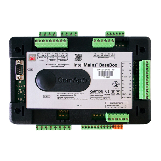
RS485 CAN1 CAN2 Extension Intercontroller RS232 Grounding Mains Aux Current measurement +PWR BOUT Binary outputs 170 (6,7") Cutout for IG-XX/IM-NT 113 x 175 mm 4,4 x 6,9” 185 (7,3") InteliMains , SW version 3.0 InteliMains-NT-BTB-3.0-Reference Guide.pdf, ©ComAp – June 2013... -
Page 14: Package Contents
Use pull up and pull down resitors on RS485 to bias the line when no device is active on the bus to prevent noise from undriven line to be interpreted as data. IM-NT-BB and IM-NTC-BB Installation instructions This portion of Instalation instructions is dedicated to the InteliMains-NT-BaseBox and InteliMains-NTC-BaseBox controllers without built-in display. -
Page 15: Mounting
Guide) standard rail (rail openings on InteliVision 5 are fixed so there is only one possible way how to mount the controller to it) InteliMains , SW version 3.0 InteliMains-NT-BTB-3.0-Reference Guide.pdf, ©ComAp – June 2013... - Page 16 Locate four screw holes on the front of the Insert provided screws and use them to secure controller the controller mounted to InteliVision 5 (screws fit into InteliVision 5 holder pieces) InteliMains , SW version 3.0 InteliMains-NT-BTB-3.0-Reference Guide.pdf, ©ComAp – June 2013...
-
Page 17: Terminal Diagram, Dimensions
AOUT - RS485 Analog output Universal Ethernet Binary outputs (NTC only) AOUT COM (NTC only) 9-12 Power Mains Aux Binary outputs Current measurement IM-NTC-BB only IM-NTC-BB only 56.5 68.5 InteliMains , SW version 3.0 InteliMains-NT-BTB-3.0-Reference Guide.pdf, ©ComAp – June 2013... -
Page 18: Package Contents
Tightening torque, allowable wire size and type, for the Field-Wiring Terminals: For Mains(Bus) Voltage, Generator Voltage a Current terminals Specified tightening torque is 0,56Nm (5,0 In-lb) Use only diameter 2,0-0,5mm (12-26AWG) conductor, rated for 90°C minimum. InteliMains , SW version 3.0 InteliMains-NT-BTB-3.0-Reference Guide.pdf, ©ComAp – June 2013... -
Page 19: Grounding (General)
Use power supply cable min. 2,5mm 2 Use fuse 1 amp for IM-NT 2 amps for IM-NT-BB or IM-NTC-BB Maximal continuous DC power supply voltage is 36VDC. AUTION Switchboard lightning strikes protection according standard regulation is expected!!! The maximum allowable current through the controller negative terminal is 3 to 8A (depends on the controller type and binary output load). -
Page 20: Voltage And Current Inputs
(WrongPhSequence detected by the controller) but this is not detected if the phases are just rotated (i.e. instead of phase sequence L1, L2, L3, phase sequence is e.g. L2, L3, L1. InteliMains , SW version 3.0 InteliMains-NT-BTB-3.0-Reference Guide.pdf, ©ComAp – June 2013... -
Page 21: Binary Input Wiring (General)
+PWR BOUT is used. If Binary outputs are connected directly to the power source, additional fuse should be used. +PWR BOUT Controller Controller Battery 24V Battery 24V InteliMains , SW version 3.0 InteliMains-NT-BTB-3.0-Reference Guide.pdf, ©ComAp – June 2013... -
Page 22: Im-Nt-Bb And Im-Ntc-Bb
Low side or High side function of binary outputs can be chosen in configuration tool GenConfig in Modules tab. This configuration is used for all binary inputs available on the controller. InteliMains , SW version 3.0 InteliMains-NT-BTB-3.0-Reference Guide.pdf, ©ComAp – June 2013... -
Page 23: Analog Input And Output Wiring
3 and Analog output wiring. Note, that battery should be also grounded to common ground in all cases! AI COM AI COM AOUT + Internal AOUT AOUT + Internal AOUT Battery 24V Battery 24V InteliMains , SW version 3.0 InteliMains-NT-BTB-3.0-Reference Guide.pdf, ©ComAp – June 2013... - Page 24 Below 750Ω = Inactive Between 750Ω and 2400Ω = Active Below 10 Ω or Over 2400Ω = sensor failure (wire shorted or interrupted) 100R AI COM AOUT + Internal AOUT Battery 24V InteliMains , SW version 3.0 InteliMains-NT-BTB-3.0-Reference Guide.pdf, ©ComAp – June 2013...
-
Page 25: Can And Rs485 Bus Wiring
≥ 75% (delay ≤ 4.4 ns/m) Propagation velocity ≥ 0.25 mm Wire crosscut ≤ 2dB/100 m Attenuation (@1MHz) RS485 BUS TOPOLOGY See the website www.can-cia.org for information about the CAN bus, specifications, etc. InteliMains , SW version 3.0 InteliMains-NT-BTB-3.0-Reference Guide.pdf, ©ComAp – June 2013... -
Page 26: Wiring Examples
3. In case of surge hazard: 3106A Paired – EIA Industrial RS-485 PLTC/CM (1x2+1 conductors) 1 – ICTURE SHORTER DISTANCES ALL NETWORK COMPONENTS WITHIN ONE ROOM 2 – ICTURE LONGER DISTANCES CONNECTION BETWEEN ROOMS WITHIN ONE BUILDING InteliMains , SW version 3.0 InteliMains-NT-BTB-3.0-Reference Guide.pdf, ©ComAp – June 2013... -
Page 27: Extension Modules (General)
CONNECTION OUT OF BUILDING IN CASE OF STORM ETC 3.12 Extension modules (general) For detailed description of several available extension modules for InteliMains please refer to the IGS-NT-Instalation Guide. InteliMains , SW version 3.0 InteliMains-NT-BTB-3.0-Reference Guide.pdf, ©ComAp – June 2013... -
Page 28: Putting It Into Operation
A direct connection can be realized by RS232 connection or USB connection (available on NTC BaseBox only). Figures below illustrate the connection setting in GenConfig and InteliMonitor. GenConfig InteliMonitor Select according COM port, adjust CAN address and enter password (optional for locked configuration). InteliMains , SW version 3.0 InteliMains-NT-BTB-3.0-Reference Guide.pdf, ©ComAp – June 2013... -
Page 29: Modem Connection
Access Code for remote connection. Enter password (optional for locked configuration). It is possible to adjust number of rings before the controller accepts the connection from modem – use Comms settings:NumberRings AA. InteliMains , SW version 3.0 InteliMains-NT-BTB-3.0-Reference Guide.pdf, ©ComAp – June 2013... -
Page 30: Internet Connection
Enter Access Code for remote connection. Enter password (optional for locked configuration). The controller must have public IP address or it must be reachable for connection in the specific network. InteliMains , SW version 3.0 InteliMains-NT-BTB-3.0-Reference Guide.pdf, ©ComAp – June 2013... -
Page 31: Airgate Connection
GenConfig InteliMonitor Enter AirGate address of a server with AirGate service (currently airgate.comap.cz). Select CAN address of the controller you want to connect to. Enter AirGate ID of the controller (InternetBridge) you want to connect to (AirGate ID is assigned automatically if the controller is properly connected to the Internet and corresponding AirGate setting is enabled. -
Page 32: Connection To Multiple Controllers
Internet multiple connection (use Internet Bridges IPs for connection to NTC BaseBox controllers as well Airgate multiple connection (fill in AirGate IDs for each controller, when using InternetBridge fill in InternetBridge AirGate ID for each controller) InteliMains , SW version 3.0 InteliMains-NT-BTB-3.0-Reference Guide.pdf, ©ComAp – June 2013... -
Page 33: Modification Of Configuration, Setpoints Etc
Do not forget that all changes in InteliMonitor are sent to the connected controller and controller immediately acts on it. Do not change CAN address of the controller or connection is lost and need to be re-established with new CAN address. InteliMains , SW version 3.0 InteliMains-NT-BTB-3.0-Reference Guide.pdf, ©ComAp – June 2013... -
Page 34: Programming Of A Controller
Open GenConfig and select “FW upgrade (default configuration)” From the following table select FW that is required or click open and browse your files to find firmware in non-default location InteliMains , SW version 3.0 InteliMains-NT-BTB-3.0-Reference Guide.pdf, ©ComAp – June 2013... - Page 35 Wait until the connection times out and following dialog appears Follow the instructions and then click OK (information regarding the location of boot jumper can be found in section 3.1.4 (IM-NT-GC) or 3.2.4 (IM-NT-BB and IM-NTC-BB) Programming starts momentarily ...
- Page 36 Additional dialog warns you that the setpoints may have improper values. Change the configuration in normal way. InteliMains , SW version 3.0 InteliMains-NT-BTB-3.0-Reference Guide.pdf, ©ComAp – June 2013...
-
Page 37: Changing The Language
Touch. If you need to use for some reason IG or IS-Display please refer to the chapter 4.4.1 for the instructions regarding built-in display which works the same as the external displays. InteliMains , SW version 3.0 InteliMains-NT-BTB-3.0-Reference Guide.pdf, ©ComAp – June 2013... -
Page 38: Password Management
Log in as a different user to change password for that particular user. Newly enabled user has always default password “0”. InteliMains , SW version 3.0 InteliMains-NT-BTB-3.0-Reference Guide.pdf, ©ComAp – June 2013... -
Page 39: Access Group Setting In Genconfig
Controller is blocked for 5 minutes if there were 6 attempts to insert incorrect password. In case of another six failed attempts (after the period of blocking elapses) the blocking period is 30, 60, 120 and 240 minutes long respectively. InteliMains , SW version 3.0 InteliMains-NT-BTB-3.0-Reference Guide.pdf, ©ComAp – June 2013... - Page 40 30 minutes after the controller reset there will be again 30 minutes remaining). After the correct password is inserted the PBP blocking period for next 6 failed attempts is reverted back to 5 minutes. InteliMains , SW version 3.0 InteliMains-NT-BTB-3.0-Reference Guide.pdf, ©ComAp – June 2013...
-
Page 41: Related Tools
PLC Editor – it can be used to create and modify built-in PLC functions For more information on Screen Editor use help in GenConfig (Help -> Screen Editor Help). For more information on PLC Editor use GenConfig Reference Guide. InteliMains , SW version 3.0 InteliMains-NT-BTB-3.0-Reference Guide.pdf, ©ComAp – June 2013... -
Page 42: Operator Guide
InteliVision 5 or 8 please refer to the section 5.1. For extensive information regarding operator control use operator guide for IGS-NT since general functions of InteliVision displays are the same for InteliGen, InteliSys and InteliMains. InteliMains , SW version 3.0 InteliMains-NT-BTB-3.0-Reference Guide.pdf, ©ComAp – June 2013... -
Page 43: Firmware And Archives
The firmware for GC controllers do not support functions described above, although it can still be used in combination with BaseBox type controllers. It is possible to use specialized InteliMains-NT firmware for InteliSys controllers. This firmware supports all the functions mentioned above. InteliMains , SW version 3.0 InteliMains-NT-BTB-3.0-Reference Guide.pdf, ©ComAp – June 2013... -
Page 44: Function Description
Acall+SMS lang SSUE SSUE Alternative brightness for It is possible to choose two different built-in levels of brightness and switch them with Alt brightness InteliGen logical binary input. display. InteliMains , SW version 3.0 InteliMains-NT-BTB-3.0-Reference Guide.pdf, ©ComAp – June 2013... - Page 45 CAN2 bus CAN bus (Intercontroller and Monitoring) to lower communication CAN bus mode (longer distance, limited to 8 controllers) mode or to higher (shorter distance, limited to 32 controllers). InteliMains , SW version 3.0 InteliMains-NT-BTB-3.0-Reference Guide.pdf, ©ComAp – June 2013...
- Page 46 Evaluation of Controller automatically detects possible CAN2 collisions on CAN2 bus (e.g. same SHxOcol detect communication shared binary outputs are broadcasted collision by two controllers on one CAN bus). InteliMains , SW version 3.0 InteliMains-NT-BTB-3.0-Reference Guide.pdf, ©ComAp – June 2013...
- Page 47 (time is update each #Time second) and there is inbuilt summer time #Date mode function. Read about history layout IME STAMP ACT modification in separate chapter. InteliMains , SW version 3.0 InteliMains-NT-BTB-3.0-Reference Guide.pdf, ©ComAp – June 2013...
- Page 48 It is possible to use permanent logical Permanent binary function that is always logical 0 or OGICAL logical 0 or 1 logical 1. It may used for various OGICAL outputs purposes. InteliMains , SW version 3.0 InteliMains-NT-BTB-3.0-Reference Guide.pdf, ©ComAp – June 2013...
- Page 49 This function is used to limit process (e.g. control parallel operation is not allowed). This DeadBusClosing Synchro enable function is complex and it is described in a separate chapter. InteliMains , SW version 3.0 InteliMains-NT-BTB-3.0-Reference Guide.pdf, ©ComAp – June 2013...
- Page 50 EMOTE ONTROL RemoteControl function from EMOTE ONTROL InteliMonitor or via Modbus commands. EMOTE ONTROL For more information please refer to a EMOTE ONTROL separate chapter. EMOTE ONTROL EMOTE ONTROL InteliMains , SW version 3.0 InteliMains-NT-BTB-3.0-Reference Guide.pdf, ©ComAp – June 2013...
- Page 51 Batt volt del archive. Please refer to a separate BusL V unbal chapter for complex step-by-step BusL Vunb del instructions on user configurable BusL I unbal protections. BusL I unb del InteliMains , SW version 3.0 InteliMains-NT-BTB-3.0-Reference Guide.pdf, ©ComAp – June 2013...
-
Page 52: Modes
It is possible to close BTB in MAN mode without voltage on bus left and bus right based on setting of DeadBusClosing setpoint. 7.2.3 AUT mode Controller closes automatically BTB if InteliMains , SW version 3.0 InteliMains-NT-BTB-3.0-Reference Guide.pdf, ©ComAp – June 2013... -
Page 53: Process Limitation
Right Bus and there is no voltage on the Left Bus It is possible to close the breaker if there is healthy voltage on BOTH one of the Buses and there is no voltage on the other one InteliMains , SW version 3.0 InteliMains-NT-BTB-3.0-Reference Guide.pdf, ©ComAp – June 2013... -
Page 54: Power Management
(ENABLE). If no Load Shedding outputs are configured, there is no record to history and no screen timer indication of the activity of this function. InteliMains , SW version 3.0 InteliMains-NT-BTB-3.0-Reference Guide.pdf, ©ComAp – June 2013... -
Page 55: Remote Alarm Messaging
COM ports or to one of I-LB modules connected to the controller via CAN2 bus. The channel address must contain complete telephone number of the recipient's PC where InteliMonitor is running in Active call receiving mode. InteliMains , SW version 3.0 InteliMains-NT-BTB-3.0-Reference Guide.pdf, ©ComAp – June 2013... -
Page 56: Example Of Setting
It is also possible to adjust number of attempts that controller performs in case of not successful Active Call – Comms settings:ActCallAttempt. The language of messages can be changed – Comms settings:Acall+SMS lang (use Translator and Languages tabs in GenConfig to adjust languages). InteliMains , SW version 3.0 InteliMains-NT-BTB-3.0-Reference Guide.pdf, ©ComAp – June 2013... -
Page 57: Controller Redundancy
CtrlHBeat FD LOG BOUT MAIN CONTROLLER LOG BIN LOG BIN Emerg. manual Setpoint Contr. Address = X Setpoint REDUNDANT CONTROLLER Watched contr = X Figure: Example of redundancy function InteliMains , SW version 3.0 InteliMains-NT-BTB-3.0-Reference Guide.pdf, ©ComAp – June 2013... -
Page 58: Force Value – Step By Step Guide
Change the name of the source setpoint (available only for Force value 1-16 setpoints) Add or remove Force value Change position of Force value functions (priority) InteliMains , SW version 3.0 InteliMains-NT-BTB-3.0-Reference Guide.pdf, ©ComAp – June 2013... -
Page 59: Regulation Loops
Sync ctrl:BRtoBLAngleReq. See also setpoint: Sync ctrl:Angle Gain The Voltage loop is active in the following situations dependending on the OLTAGE LOOP application. For more information see the table below. InteliMains , SW version 3.0 InteliMains-NT-BTB-3.0-Reference Guide.pdf, ©ComAp – June 2013... -
Page 60: Pi Regulation Adjustment
0 to disable it. Adjust the setpoint back to it's original value after the adjustment is finished. AUTION Be ready to press emergency stop button in case the regulation loop would start to behave unacceptable while it is beeing adjusted. InteliMains , SW version 3.0 InteliMains-NT-BTB-3.0-Reference Guide.pdf, ©ComAp – June 2013... -
Page 61: Values For Continuous Writing From External Sources
The timer is activated every "x-th" week on selected weekdays. The week period EEKLY "x" is adjustable. E.g. the timer can be adjusted to every 2nd week on monday and friday. InteliMains , SW version 3.0 InteliMains-NT-BTB-3.0-Reference Guide.pdf, ©ComAp – June 2013... - Page 62 0:00, timer duration 0:30 min. 3. The setpoint Timer settings:TimerChannel 2 is adjusted to "once" mode, starting date/time 1.5.2010 at 01:00, timer duration 3:00 hrs. InteliMains , SW version 3.0 InteliMains-NT-BTB-3.0-Reference Guide.pdf, ©ComAp – June 2013...
-
Page 63: History Related Functions
CAN. When the value is changed in one controller, it sends its new value to all other controllers that are connected to the same CAN bus and they update their time and date values and setpoints accordingly. InteliMains , SW version 3.0 InteliMains-NT-BTB-3.0-Reference Guide.pdf, ©ComAp – June 2013... -
Page 64: Summer Time Mode
Summer Time Mode function may be enabled and disabled by user. It is possible to set if the controller is located in the northern or southern hemisphere as well. SummerTimeMode implemented in ComAp controllers is based on CET summer time which means: ... -
Page 65: Virtual Peripheral Inputs-Outputs (Vpio) Module
VPIO module. Inputs on VPIO module work the same way as standard input of the controller (i.e. it can be assigned function and protection). For example of this function please refer to the chapter Remote Control function. InteliMains , SW version 3.0 InteliMains-NT-BTB-3.0-Reference Guide.pdf, ©ComAp – June 2013... -
Page 66: Shared Inputs And Outputs
If SHUTDOWN (RED) protection is chosen, it is interpreted in InteliMains as Mains Protect with Reset type protection. For more information on Protection types and alarms please refet to the chapter Protection and Alarms management. InteliMains , SW version 3.0 InteliMains-NT-BTB-3.0-Reference Guide.pdf, ©ComAp – June 2013... -
Page 67: Distributed Binary Inputs And Outputs
If SHUTDOWN (RED) protection is chosen, it is interpreted in InteliMains as Mains Protect with Reset type protection. For more information on Protection types and alarms please refet to the chapter Protection and Alarms management. InteliMains , SW version 3.0 InteliMains-NT-BTB-3.0-Reference Guide.pdf, ©ComAp – June 2013... -
Page 68: Modbus Reading And Writing
Users can define Modbus registers from 42873 to 43000. Values, setpoints and Alarm states can be specified for these new Modbus registers to prepare the Modbus protocol for batch reading and writing or to standardize Modbus protocol between FW versions or branches. InteliMains , SW version 3.0 InteliMains-NT-BTB-3.0-Reference Guide.pdf, ©ComAp – June 2013... -
Page 69: Analog Input Sensors And User Sensors
Default sensors: PT100/°C, PT1000/°C, NI1000/°C, PT100/°F, PT1000/°F, NI1000/°F, 4-20mA active, 0-2400ohm, 0-2.4V, Tristate There is “electronic” type of sensor available for Shared Analog Inputs which can be used to interpret shared data over CAN bus. InteliMains , SW version 3.0 InteliMains-NT-BTB-3.0-Reference Guide.pdf, ©ComAp – June 2013... -
Page 70: Languages And Translator Tool In Genconfig
In GenConfig you can easily set any object in Screen Editor to show or hide based on activation of particular Logical Binary Input available for users. Below, there is diagram showing the setup of User Mask function in Screen Editor. InteliMains , SW version 3.0 InteliMains-NT-BTB-3.0-Reference Guide.pdf, ©ComAp – June 2013... -
Page 71: Plc Functions
(i.e. Remote display or PC-InteliMonitor) can be switched to different language. Use PC- GenConfig - Translator tool to translate texts to another language. Default application archives contain all texts in English only. InteliMains , SW version 3.0 InteliMains-NT-BTB-3.0-Reference Guide.pdf, ©ComAp – June 2013... -
Page 72: Protections And Alarm Management
8 Protections and Alarm management ComAp mains controllers provide following range of mains protections. For each protection adjustable limit and time delay are available. IM-NT, ANSI ROTECTION CODE IM-NT-BB Overvoltage Undervoltage Voltage Unbalance and Phase-sequence Overfrequency ... -
Page 73: Protection Types
Configured in Protections tab in default archive: Bus Left Voltage Unbalance BusL protect: BusL V unbal; BusL V unb del Bus Left Current Unbalance BusL protect: BusL I unbal; BusL I unb del InteliMains , SW version 3.0 InteliMains-NT-BTB-3.0-Reference Guide.pdf, ©ComAp – June 2013... -
Page 74: Bus Left Voltage And Frequency Protections - Limits And Indications
Controller provides vast possibilies for user configurable protections. There are several protections that configured by default in standard configuration. For step-by-setp guide on how to configure your own protections please go to chapter 7.1.6.2. InteliMains , SW version 3.0 InteliMains-NT-BTB-3.0-Reference Guide.pdf, ©ComAp – June 2013... - Page 75 Toggle normally closed/normally open Defines when the protection is active Defines protection delay 8.1.6.2.2 Analog Input protection configuration Open I/O tab in GenCofig and adjust parameters that are described below. InteliMains , SW version 3.0 InteliMains-NT-BTB-3.0-Reference Guide.pdf, ©ComAp – June 2013...
- Page 76 You need to prepare two separate protections for level 1 and level 2. Select the value for protection first and then use Wizard – it will take you through all the steps and help you adjust them correctly. InteliMains , SW version 3.0 InteliMains-NT-BTB-3.0-Reference Guide.pdf, ©ComAp – June 2013...
-
Page 77: Reset Actual Alarms Selection
MAINS: If any Mains incomer is connected to the bus (provided that all corresponding Bus Tie Breakers are closed as well) and InteliMains is not measuring correct values on Bus it automatically detects bus measurement error. InteliMains , SW version 3.0 InteliMains-NT-BTB-3.0-Reference Guide.pdf, ©ComAp – June 2013... -
Page 78: Peripheral Modules Error Detection
Change the type to the BrkOpen w/Reset If more than one module are configured, the BreakerOpen with Reset protection is issued when any of these modules is detected as missing! InteliMains , SW version 3.0 InteliMains-NT-BTB-3.0-Reference Guide.pdf, ©ComAp – June 2013... -
Page 79: Circuit Breakers Operation Sequence, Mgcb/Mcb Fail Detection
LEDs on the panel, switching the regulations, CB fail evaluation, etc. All pulse outputs for CB in following diagrams may be long 5s if the CB is not used for synchronization in that particular instance. InteliMains , SW version 3.0 InteliMains-NT-BTB-3.0-Reference Guide.pdf, ©ComAp – June 2013... -
Page 80: Following Graphs Depict Possible Cb Sequences
OFF pulse and no CB fail is issued. This would be issued after the second unsuccessfull attempt. ON pulse has finished and CB status is not =1. CB fail is issued immediatelly InteliMains , SW version 3.0 InteliMains-NT-BTB-3.0-Reference Guide.pdf, ©ComAp – June 2013... - Page 81 Further behavior of UV output depends on the system status. In case of transition to cooling stays off, if the Cb was opened manually and the engine keeps running, it activates again after timeout elapses. InteliMains , SW version 3.0 InteliMains-NT-BTB-3.0-Reference Guide.pdf, ©ComAp – June 2013...
- Page 82 BTB can be opened externally and this state is always confirmed by the controller and no alarm is issued. The reaction of the controller is shown in next graphs. Alarm detection is immediate InteliMains , SW version 3.0 InteliMains-NT-BTB-3.0-Reference Guide.pdf, ©ComAp – June 2013...
- Page 83 Breaker opened externally, one Bus only OK, DeadBusClosing causes breaker to try closing BTB fail BTB fdk Synchro BTB UV Coil BTB OFF Coil BTB ON Coil BTB Close/Open InteliMains , SW version 3.0 InteliMains-NT-BTB-3.0-Reference Guide.pdf, ©ComAp – June 2013...
-
Page 84: Follow Function For Breaker Control In Aut Mode
ProcessControl:Synchro enable. Synchronization in COX(FOLLOW) does not have any timeout and controller keeps voltages synchronized indefinitely (i.e. until F ORCE SYNC opened or the breaker is closed externally). InteliMains , SW version 3.0 InteliMains-NT-BTB-3.0-Reference Guide.pdf, ©ComAp – June 2013... -
Page 85: Controller Operation States
E description in the APPENDIX of this MERG MANUAL manual or see context help in GenConfig. Init Initialization of controller. In this state, controller is not fully functional. InteliMains , SW version 3.0 InteliMains-NT-BTB-3.0-Reference Guide.pdf, ©ComAp – June 2013... -
Page 86: Appendix
APPENDIX InteliMains , SW version 3.0 InteliMains-NT-BTB-3.0-Reference Guide.pdf, ©ComAp – June 2013... -
Page 87: List Of Objects
BusLeftCTsec AuxCurrCTprim AuxCurrCTsec FixVoltProtSelect Nominal Freq ControllerMode Local buttons DispBaklightTO ConvCoefPulse1 ConvCoefPulse2 ConvCoefPulse3 ConvCoefPulse4 11.1.3 Setpoints - Comms settings ControllerName LB/UART Log Contr. adress RS232(1) mode RS232(2) mode RS232(1)MBCSpd InteliMains , SW version 3.0 InteliMains-NT-BTB-3.0-Reference Guide.pdf, ©ComAp – June 2013... -
Page 88: Setpoints - Comprotsetting
Batt >V Batt <V Batt volt del 11.1.6 Setpoints - BusL protect BusL2POvrldPro OverldStrtEval 2POvrldStEvDel BusL2Inom prot BusL2Inom del BusLVolt prot BusLeft >V BusLeft <V BusLeft V del BusLfreq prot InteliMains , SW version 3.0 InteliMains-NT-BTB-3.0-Reference Guide.pdf, ©ComAp – June 2013... -
Page 89: Setpoints - Busr Protect
%LdResStrt 3 %LdResStop 3 %LdResStrt 4 %LdResStop 4 NextStrt Del OverldNext Del NextStopDel SlowStopDel MinRunPower 1 MinRunPower 2 MinRunPower 3 RunHrsMaxDiff PwrBandContr 1 PwrBandContr 2 PwrBandContr 3 PwrBandContr 4 InteliMains , SW version 3.0 InteliMains-NT-BTB-3.0-Reference Guide.pdf, ©ComAp – June 2013... -
Page 90: Setpoints - Sync Ctrl
Force value 14 Force value 15 Force value 16 ExtValue1LoLim ExtValue2LoLim ExtValue3LoLim ExtValue4LoLim ExtValue1HiLim ExtValue2HiLim ExtValue3HiLim ExtValue4HiLim ExtValue1 rate ExtValue2 rate ExtValue3 rate ExtValue4 rate ExtValue1deflt ExtValue2deflt ExtValue3deflt ExtValue4deflt InteliMains , SW version 3.0 InteliMains-NT-BTB-3.0-Reference Guide.pdf, ©ComAp – June 2013... -
Page 91: Setpoints - Load Shedding
MainsP w/Reset AcallCH1-Type AcallCH1-Addr AcallCH2-Type AcallCH2-Addr AcallCH3-Type AcallCH3-Addr AcallCH4-Type AcallCH4-Addr AcallCH5-Type AcallCH5-Addr NumberRings AA ActCallAttempt Acall+SMS lang 11.1.15 Setpoints - Date/Time Time stamp act Time Stamp Per #SummerTimeMod #Time #Date InteliMains , SW version 3.0 InteliMains-NT-BTB-3.0-Reference Guide.pdf, ©ComAp – June 2013... -
Page 92: Values – List
BusR V L1-N BusR V L2-N BusR V L3-N BusR V BusR V L1-L2 BusR V L2-L3 BusR V L3-L1 BusR V unbal I Aux Slip freq Angle BusR V [kV] InteliMains , SW version 3.0 InteliMains-NT-BTB-3.0-Reference Guide.pdf, ©ComAp – June 2013... -
Page 93: Values Group - Gen-Sets
11.2.4 Values group - Control loops 11.2.5 Values group - Pwr management TotAvlbPnom TotRunPnom Act Reserve LoadRes Start LoadRes Stop ActRes rel ResStart rel ResStp rel 11.2.6 Values group - Force value ExtValue1 ExtValue2 InteliMains , SW version 3.0 InteliMains-NT-BTB-3.0-Reference Guide.pdf, ©ComAp – June 2013... -
Page 94: Values Group - Load Shedding
11.2.12 Values group - Info Controller mode SW version Application SW branch Password decode CAN16 CAN32 Reg16 Reg32 GL16 GL32 Breaker state Timer text Timer val NextTime1-4 NextDate1-4 NextTime5-8 NextDate5-8 NextTime9-12 InteliMains , SW version 3.0 InteliMains-NT-BTB-3.0-Reference Guide.pdf, ©ComAp – June 2013... -
Page 95: Values Group - Statistics
Timer block 2 Timer block 3 Timer block 4 Timer block 5 Timer block 6 Timer block 7 Timer block 8 Timer block 9 Timer block 10 Timer block 11 InteliMains , SW version 3.0 InteliMains-NT-BTB-3.0-Reference Guide.pdf, ©ComAp – June 2013... -
Page 96: Binary Output Functions – List
Lang sel D#2 B Lang sel D#2 C 11.4 Binary Output Functions – List 11.4.1 Common functions User Button 1 User Button 2 User Button 3 User Button 4 User Button 5 InteliMains , SW version 3.0 InteliMains-NT-BTB-3.0-Reference Guide.pdf, ©ComAp – June 2013... -
Page 97: Breaker Control
CtrlHeartBeat CtrlHBeat FD Logical 0 Logical 1 11.4.4 Fixed protections output VbusL <> VbusR <> fbusL <> fbusR <> BusL fail BusR fail Horn Alarm Common Wrn Common Fls InteliMains , SW version 3.0 InteliMains-NT-BTB-3.0-Reference Guide.pdf, ©ComAp – June 2013... -
Page 98: Power Management
UnivState 12 UnivState 13 UnivState 14 UnivState 15 11.5 Analog Input Functions – List MLC:I/E-PbL MPF:I/E-QbL LCD brightness Cold Temp 1 Cold Temp 2 Cold Temp 3 Cold Temp 4 InteliMains , SW version 3.0 InteliMains-NT-BTB-3.0-Reference Guide.pdf, ©ComAp – June 2013... -
Page 99: Setpoints
#SysLdCtrl PtM = BASELOAD control loop (like in SPtM) to maintain the load. Load sharing is not performed, the InteliMains InteliMains , SW version 3.0 InteliMains-NT-BTB-3.0-Reference Guide.pdf, ©ComAp – June 2013... - Page 100 # sign in the name of this setpoint marks that this setpoint is shared among all controllers connected by CAN2 bus. 12.2.1.3 Setpoint: #SysLdCtrl PtM Group Process Control Range BASELOAD, LDSHARING [-] [units] Related InteliMains , SW version 3.0 InteliMains-NT-BTB-3.0-Reference Guide.pdf, ©ComAp – June 2013...
- Page 101 The gen-sets are controlled by their load control loops (i.e. as in SPtM) to provide constant proportional part of the requested system baseload (see #SysBaseLoad). The InteliMains does not play active role regarding load control in parallel-to-mains operation. InteliMains , SW version 3.0 InteliMains-NT-BTB-3.0-Reference Guide.pdf, ©ComAp – June 2013...
- Page 102 DISTRIBUTED SYSTEM BASELOAD LDSHARI The gen-sets are controlled by the InteliMains through the load sharing line. The InteliMains load control mode is selected by the setpoint Load ctrl PtM. InteliMains , SW version 3.0 InteliMains-NT-BTB-3.0-Reference Guide.pdf, ©ComAp – June 2013...
- Page 103 InteliMains , SW version 3.0 InteliMains-NT-BTB-3.0-Reference Guide.pdf, ©ComAp – June 2013 OAD CONTROL IN FROM NTELI AINS OVER...
- Page 104 # sign in the name of this setpoint marks that this setpoint is shared among all controllers connected by CAN2 bus. 12.2.1.5 Setpoint: I/E-PbL meas Group Process Control Range [units] NONE, CT INPUTS, ANALOG INPUT [-] InteliMains , SW version 3.0 InteliMains-NT-BTB-3.0-Reference Guide.pdf, ©ComAp – June 2013...
- Page 105 I/E- PbL meas is set to CT INPUTS, the I/E-QbL meas should not be set to ANALOG INPUT and vice versa. InteliMains , SW version 3.0 InteliMains-NT-BTB-3.0-Reference Guide.pdf, ©ComAp – June 2013...
- Page 106 This setpoint selects how the IM-NT cooperates with other IM-NT in systems where one common busbar is supplied from many mains incomers, which are controlled by many IM-NT controllers. InteliMains , SW version 3.0 InteliMains-NT-BTB-3.0-Reference Guide.pdf, ©ComAp – June 2013...
- Page 107 Closing to dead bus is enabled if there is healty voltage on busL (i.e. dead busR). Controller in AUT mode does not closes breaker unles there is healthy voltage on busL or on both InteliMains , SW version 3.0 InteliMains-NT-BTB-3.0-Reference Guide.pdf, ©ComAp – June 2013...
- Page 108 CAN-based rendundant systems. Adjust this setpoint to 0 if the controller is not used as redundant or if wired rendundancy system is used. Learn more about redundant systems in the chapter Redundant controllers. InteliMains , SW version 3.0 InteliMains-NT-BTB-3.0-Reference Guide.pdf, ©ComAp – June 2013...
-
Page 109: Group: Basic Settings
100V secondary range are used or for alternative American (120V) measurement. 12.2.2.3 Setpoint: BusR VT ratio Group Basic Settings Range [units] 0.10 .. 500.00 [V/V] InteliMains , SW version 3.0 InteliMains-NT-BTB-3.0-Reference Guide.pdf, ©ComAp – June 2013... - Page 110 Force value possible Description This setpoint is used to adjust the nominal mains voltage (phase to neutral). If you do not know the phase-neutral nominal voltage, you can adjust the InteliMains , SW version 3.0 InteliMains-NT-BTB-3.0-Reference Guide.pdf, ©ComAp – June 2013...
- Page 111 For 415 V on BusL it is typical to open BTB when voltage reaches 440 V or 390 V. Since the setpoint is adjusted to 400 V corresponding protection setpoints need to be adjusted to BusRight >V = 106% and BusRight <V = 97 InteliMains , SW version 3.0 InteliMains-NT-BTB-3.0-Reference Guide.pdf, ©ComAp – June 2013...
- Page 112 This setpoint is also recalculated automatically when the phase-neutral nominal voltage busRNomV is changed. This setpoint can be used if you know the phase-phase nominal voltage only. The controller will recalculate the phase-neutral nominal voltage InteliMains , SW version 3.0 InteliMains-NT-BTB-3.0-Reference Guide.pdf, ©ComAp – June 2013...
- Page 113 The maximum measurable input current to the controller current terminals is 11A. ARNING Do not discconnect the CT terminals from the controller while there is nonzero current in the CT primary circuit! InteliMains , SW version 3.0 InteliMains-NT-BTB-3.0-Reference Guide.pdf, ©ComAp – June 2013...
- Page 114 BusLeftCTprim. The CT secondary nominal current is adjustable only in IM-NTC. The IM-NT has the CT secondary nominal current adjusted fixedly to 5A regardless of this setpoint. InteliMains , SW version 3.0 InteliMains-NT-BTB-3.0-Reference Guide.pdf, ©ComAp – June 2013...
- Page 115 The busL/busR voltage protections are based on phase-to-neutral voltages. PHASE-PHASE The busL/busR voltage protections are based on phase-to-phase voltages. 12.2.2.16 Setpoint: Nominal Freq Group Basic Settings Range [units] 50 Hz, 60 Hz [-] Related FW InteliMains , SW version 3.0 InteliMains-NT-BTB-3.0-Reference Guide.pdf, ©ComAp – June 2013...
- Page 116 Controller closes automatically BTB if bus voltages are within the limits (Phase window, Voltage window) there is voltage on one of the buses and closing to dead InteliMains , SW version 3.0 InteliMains-NT-BTB-3.0-Reference Guide.pdf, ©ComAp – June 2013...
- Page 117 Both built-in buttons and binary inputs for external buttons are enabled. In case that additional IV display is connected to a controller it behaves in the way described below. InteliMains , SW version 3.0 InteliMains-NT-BTB-3.0-Reference Guide.pdf, ©ComAp – June 2013...
- Page 118 The binary inputs for external buttonst may be the following (depending on used application): GCBButton, MCBButton, MGCBButton, FDRButton, BTBButton, FaultResButton, HornResButton, StartButton, StopButton etc. IGS-NT-BB with IV-8 display InteliMains , SW version 3.0 InteliMains-NT-BTB-3.0-Reference Guide.pdf, ©ComAp – June 2013...
- Page 119 The binary inputs for external buttonst may be the following (depending on used application): GCBButton, MCBButton, MGCBButton, FDRButton, BTBButton, FaultResButton, HornResButton, StartButton, StopButton etc. 12.2.2.19 Setpoint: DispBaklightTO Group Basic settings Range [units] OFF, 1-240 min, NO TIMEOUT [min] InteliMains , SW version 3.0 InteliMains-NT-BTB-3.0-Reference Guide.pdf, ©ComAp – June 2013...
- Page 120 ConvCoefPulse1/2/3/4. The converted values are visible in statistics – values PulseCounter 1/2/3/4. These values can be reset using Statistics window in InteliMonitor. 12.2.2.21 Setpoint: ConvCoefPulse2 Group Basic settings Range [units] 1 .. 65000 [/X] Related FW InteliMains , SW version 3.0 InteliMains-NT-BTB-3.0-Reference Guide.pdf, ©ComAp – June 2013...
- Page 121 1/2/3/4 and output statistic values PulseCounter 1/2/3/4. The ratio defines how many pulses (rising edges) have to be sensed at the input in order to increase the output value. Unfinished “invisible” parts are stored in the InteliMains , SW version 3.0 InteliMains-NT-BTB-3.0-Reference Guide.pdf, ©ComAp – June 2013...
-
Page 122: Group: Comms Settings
When logging is enabled in certain conditions the history may be filled up with large number of records related to the communication and important records may be overwritten quite fast. InteliMains , SW version 3.0 InteliMains-NT-BTB-3.0-Reference Guide.pdf, ©ComAp – June 2013... - Page 123 Selectable by the setpoint RS485(1) conv. (not available in IG-NT-BB, IG-NTC-BB, IS-NTC-BB and IS-NT - see RS485(1) conv.). See the diagram of all related terminals in the chapter Communication. InteliMains , SW version 3.0 InteliMains-NT-BTB-3.0-Reference Guide.pdf, ©ComAp – June 2013...
- Page 124 This setpoint selects the connection type for the serial port COM2. Available as RS232 or RS485 in the IG-NTC and IS-NT controllers. Selectable by the setpoint RS485(2) conv.. Available only as RS485 in the IG-NTC-BB and IS-NTC-BB InteliMains , SW version 3.0 InteliMains-NT-BTB-3.0-Reference Guide.pdf, ©ComAp – June 2013...
- Page 125 The RS232 connector is no more available in hardware version 2.0 and above. The COM2 port is redirected to the RS485(2) terminals all the time. That means modem is not supported at COM2 in these hardware versions. InteliMains , SW version 3.0 InteliMains-NT-BTB-3.0-Reference Guide.pdf, ©ComAp – June 2013...
- Page 126 "AT" prefix, are separated with semicolon and maximal length is 31 characters. The setpoint can't be modified via the IG-NT built-in terminal. 12.2.3.9 Setpoint: RS232(2)MdmIni Group Comms settings InteliMains , SW version 3.0 InteliMains-NT-BTB-3.0-Reference Guide.pdf, ©ComAp – June 2013...
- Page 127 See the setpoint RS232(1) mode. This setpoint must be set to DISABLED at controllers that do not have internal display. i.e. InteliVision-5 or InteliVision-8 is connected to the RS485(1) terminals. InteliMains , SW version 3.0 InteliMains-NT-BTB-3.0-Reference Guide.pdf, ©ComAp – June 2013...
- Page 128 8C: Low speed CAN (50 kbps) applicable up to 8 controllers, CAN bus length limited up to 900 meters. Change of this setpoint is applied after the controller is switched off and on again. InteliMains , SW version 3.0 InteliMains-NT-BTB-3.0-Reference Guide.pdf, ©ComAp – June 2013...
- Page 129 12.2.3.15 Setpoint: CANAddrSwitch1 Group Comms settings Range [units] Related FW InteliMains , SW version 3.0 InteliMains-NT-BTB-3.0-Reference Guide.pdf, ©ComAp – June 2013...
- Page 130 CAN2 bus to prevent CAN bus collision. Controller address is set up to different address if another unit with the same address is detected on the CAN bus. InteliMains , SW version 3.0 InteliMains-NT-BTB-3.0-Reference Guide.pdf, ©ComAp – June 2013...
- Page 131 "plug and play". When this type of connection is opening the controller is specified by it's AirGate ID and the IP address does not play any role. InteliMains , SW version 3.0 InteliMains-NT-BTB-3.0-Reference Guide.pdf, ©ComAp – June 2013...
- Page 132 DHCP server. It is not possible to change the setpoint value manually in this setting (the value is immediately reverted back by controller communication module IB-COM). InteliMains , SW version 3.0 InteliMains-NT-BTB-3.0-Reference Guide.pdf, ©ComAp – June 2013...
- Page 133 This setpoint is used to adjust the port, which is used for ethernet connection to a PC with any of ComAp PC program (i.e. InteliMonitor, GenConfig). This setpoint should be adjusted to 23, which is the default port used by all ComAp PC programs.
- Page 134 Related FW Description This setpoint is used for entering the domain name or IP address of the AirGate server. Use the free AirGate server provided by ComAp at address airgate.comap.cz if your company does not operate it's own AirGate server. 12.2.3.25...
- Page 135 Related FW Description Enter an existing e-mail address into this setpoint. This address will be used as sender address in active e-mails that will be sent from the controller. InteliMains , SW version 3.0 InteliMains-NT-BTB-3.0-Reference Guide.pdf, ©ComAp – June 2013...
- Page 136 DHCP server. It is not possible to change the setpoint value manually in this setting (the value is immediately reverted back by controller communication module IB-COM). InteliMains , SW version 3.0 InteliMains-NT-BTB-3.0-Reference Guide.pdf, ©ComAp – June 2013...
-
Page 137: Group: Comprotsetting
Protections configured at a binary inputs can have either fixed 0.5s evaluation delay or there are three independent delay setpoints and one of them can be assigned to each particular binary input protection. InteliMains , SW version 3.0 InteliMains-NT-BTB-3.0-Reference Guide.pdf, ©ComAp – June 2013... - Page 138 This setpoint adjusts the delay after the binary input Force block 2 has been Description deactivated, when the alarms configured as Force block #2 are started to be evaluated. 12.2.4.7 Setpoint: ForceBlockDel3 Group ComProtSetting InteliMains , SW version 3.0 InteliMains-NT-BTB-3.0-Reference Guide.pdf, ©ComAp – June 2013...
-
Page 139: Group: Analog Protect
ENABLED position corresponds to the method how the IG-classic and IS- classic controllers handled the alarms. 12.2.5 Group: Analog protect 12.2.5.1 Setpoint: Batt >V Group Analog protect Range [units] 8.0 .. 40.0 [V] InteliMains , SW version 3.0 InteliMains-NT-BTB-3.0-Reference Guide.pdf, ©ComAp – June 2013... -
Page 140: Group: Busl Protect
DISABLED, ENABLED [-] Related FW Force value possible Description Enables or disables the busL overload (IDMT) protection. This protection is evaluated with variable delay. For more information see setpoint 2POvrldStEvDel. InteliMains , SW version 3.0 InteliMains-NT-BTB-3.0-Reference Guide.pdf, ©ComAp – June 2013... - Page 141 The reaction time of the thermal overload protection is not fixed; it depends on how much is the load above the limit (base level). The higher is the load the shorter the reaction time will be. InteliMains , SW version 3.0 InteliMains-NT-BTB-3.0-Reference Guide.pdf, ©ComAp – June 2013...
- Page 142 The reaction time of the IDMT overcurrent protection is not fixed; it depends on how much is the actual current above the limit (nominal). The higher is the overcurrent the shorter the reaction time will be. InteliMains , SW version 3.0 InteliMains-NT-BTB-3.0-Reference Guide.pdf, ©ComAp – June 2013...
- Page 143 In this case busL is considered healthy if there is any voltage. InteliMains , SW version 3.0 InteliMains-NT-BTB-3.0-Reference Guide.pdf, ©ComAp – June 2013...
- Page 144 It is possible to disable this protection through setpoint BusLVolt prot. 12.2.6.9 Setpoint: BusLeft V del Group BusL protect Range [units] 0.00 .. 600.00 [s] InteliMains , SW version 3.0 InteliMains-NT-BTB-3.0-Reference Guide.pdf, ©ComAp – June 2013...
- Page 145 The protection activates if the frequency in phase L3 gets over the threshold for time longer than BusLeft f del. The busL overfrequency protection is History record type - for more information on protection types please refer to alarm types section. InteliMains , SW version 3.0 InteliMains-NT-BTB-3.0-Reference Guide.pdf, ©ComAp – June 2013...
- Page 146 Group BusL protect Range [units] DISABLED, ENABLED [-] Related FW Force value possible Description Althought this setpoint is located in BusL protect it is valid for both busL and InteliMains , SW version 3.0 InteliMains-NT-BTB-3.0-Reference Guide.pdf, ©ComAp – June 2013...
- Page 147 Range [units] 0.0 .. 600.0 [s] Related FW Description This setpoint adjusts delay for busL voltage unbalance alarm (see BusL V unbal). 12.2.6.17 Setpoint: BusL I unbal Group BusL protect InteliMains , SW version 3.0 InteliMains-NT-BTB-3.0-Reference Guide.pdf, ©ComAp – June 2013...
-
Page 148: Group: Busr Protect
In this case BusR is considered healthy if there is any voltage. 12.2.7.2 Setpoint: BusRight >V Group BusR protect BusRight <V .. 150 [%] Range [units] InteliMains , SW version 3.0 InteliMains-NT-BTB-3.0-Reference Guide.pdf, ©ComAp – June 2013... - Page 149 Setpoint: BusRight V del Group BusR protect Range [units] 0.00 .. 600.00 [s] Related FW Description This setpoint adjusts delay for busR under- (BusRight <V) and overvoltage (BusRight >V) protections. InteliMains , SW version 3.0 InteliMains-NT-BTB-3.0-Reference Guide.pdf, ©ComAp – June 2013...
- Page 150 This setpoint determines the treshold for busR overfrequency protection. This protection is evaluated with delay given by setpoint BusRight f del and it is history record type. 12.2.7.7 Setpoint: BusRight <f Group BusR protect InteliMains , SW version 3.0 InteliMains-NT-BTB-3.0-Reference Guide.pdf, ©ComAp – June 2013...
- Page 151 This protection is history record type and its delay is set by the setpoint BusR Vunb del. 12.2.7.10 Setpoint: BusR Vunb del Group BusR protect Range [units] 0.0 .. 600.0 [s] InteliMains , SW version 3.0 InteliMains-NT-BTB-3.0-Reference Guide.pdf, ©ComAp – June 2013...
-
Page 152: Group: Pwr Management
%. # sign in the name of this setpoint marks that this setpoint is shared among all controllers connected by CAN2 bus. InteliMains , SW version 3.0 InteliMains-NT-BTB-3.0-Reference Guide.pdf, ©ComAp – June 2013... - Page 153 (if more gen-sets are needed, please use IGS-NT-PSC firmware in additional controller - more information about this FW can be found on our webpages www.comap.cz). Note that this priority swapping function may be used only if #Pwr mgmt mode set to ABS (kW).
- Page 154 If the MCB feedback is closed, Power management is started with 1s delay after the input Sys start/stop closing - InteliMains , SW version 3.0 InteliMains-NT-BTB-3.0-Reference Guide.pdf, ©ComAp – June 2013...
- Page 155 (according to their priority and nominal power). There is a possiblity to assign this setpoint negative number. This can be used in some situations to allow genset start after Sys Start/Stop gets active. InteliMains , SW version 3.0 InteliMains-NT-BTB-3.0-Reference Guide.pdf, ©ComAp – June 2013...
- Page 156 The currently active reserve set is selected by binary inputs Load res Load res 3 Load res 4. If none of these inputs is active the set #1 is selected. InteliMains , SW version 3.0 InteliMains-NT-BTB-3.0-Reference Guide.pdf, ©ComAp – June 2013...
- Page 157 # sign in the name of this setpoint marks that this setpoint is shared among all controllers connected by CAN2 bus. 12.2.8.10 Setpoint: #LoadResStrt 3 Group Pwr Management -32000 .. LoadResStop 3 [kX] Range [units] InteliMains , SW version 3.0 InteliMains-NT-BTB-3.0-Reference Guide.pdf, ©ComAp – June 2013...
- Page 158 The reserve for stop must be always adjusted higher than the reserve for start. # sign in the name of this setpoint marks that this setpoint is shared among all controllers connected by CAN2 bus. InteliMains , SW version 3.0 InteliMains-NT-BTB-3.0-Reference Guide.pdf, ©ComAp – June 2013...
- Page 159 = ABS (kW) or ABS (kVA) if the reserve set #4 is active. Learn more about reserves in the chapter Reserves, minimal running power. The currently active reserve set is selected by binary inputs Load res Load InteliMains , SW version 3.0 InteliMains-NT-BTB-3.0-Reference Guide.pdf, ©ComAp – June 2013...
- Page 160 This setpoint is used to adjust the load reserve for stop in relative mode. i.e. Pwr mgmt mode = REL (%) if the reserve set #1 is active. Learn more about InteliMains , SW version 3.0 InteliMains-NT-BTB-3.0-Reference Guide.pdf, ©ComAp – June 2013...
- Page 161 # sign in the name of this setpoint marks that this setpoint is shared among all controllers connected by CAN2 bus. 12.2.8.17 Setpoint: #%LdResStop 2 Group Pwr Management Range [units] %LdResStrt 2 .. 110 [%] Related FW InteliMains , SW version 3.0 InteliMains-NT-BTB-3.0-Reference Guide.pdf, ©ComAp – June 2013...
- Page 162 # sign in the name of this setpoint marks that this setpoint is shared among all controllers connected by CAN2 bus. 12.2.8.19 Setpoint: #%LdResStop 3 Group Pwr Management Range [units] %LdResStrt 3 .. 110 [%] InteliMains , SW version 3.0 InteliMains-NT-BTB-3.0-Reference Guide.pdf, ©ComAp – June 2013...
- Page 163 # sign in the name of this setpoint marks that this setpoint is shared among all controllers connected by CAN2 bus. 12.2.8.21 Setpoint: #%LdResStop 4 Group Pwr Management InteliMains , SW version 3.0 InteliMains-NT-BTB-3.0-Reference Guide.pdf, ©ComAp – June 2013...
- Page 164 #NextStrt del will begin to count down. But if the load raises too quickly it might happen that the system gets overloaded already before the delay #NextStrt del reaches zero. InteliMains , SW version 3.0 InteliMains-NT-BTB-3.0-Reference Guide.pdf, ©ComAp – June 2013...
- Page 165 If there isn't any available gen-set to start, the alarm is not suppressed. # sign in the name of this setpoint marks that this setpoint is shared among all controllers connected by CAN2 bus. InteliMains , SW version 3.0 InteliMains-NT-BTB-3.0-Reference Guide.pdf, ©ComAp – June 2013...
- Page 166 When more than one binary input MinRunPower is activated then MinRunPower with the highest number is active. # sign in the name of this setpoint marks that this setpoint is shared among all controllers connected by CAN2 bus. InteliMains , SW version 3.0 InteliMains-NT-BTB-3.0-Reference Guide.pdf, ©ComAp – June 2013...
- Page 167 # sign in the name of this setpoint marks that this setpoint is shared among all controllers connected by CAN2 bus. 12.2.8.30 Setpoint: #PwrBandContr 1 Group Pwr management Range [units] 1, 2, 1+2, 3, 1+3, 2+3, 1+2+3 [-] InteliMains , SW version 3.0 InteliMains-NT-BTB-3.0-Reference Guide.pdf, ©ComAp – June 2013...
- Page 168 This setpoint is used to select the gen-sets which will run within the power band #3 if the optimalization according to gen-set size is active. Learn more about this topis in the chapter Gen-set size optimalization. InteliMains , SW version 3.0 InteliMains-NT-BTB-3.0-Reference Guide.pdf, ©ComAp – June 2013...
- Page 169 Gen-set size optimalization. # sign in the name of this setpoint marks that this setpoint is shared among all controllers connected by CAN2 bus. InteliMains , SW version 3.0 InteliMains-NT-BTB-3.0-Reference Guide.pdf, ©ComAp – June 2013...
-
Page 170: Group: Sync Ctrl
If this particular controller is not used for the group link function adjust this setpoint to 1 (COMMON). 12.2.9 Group: Sync ctrl 12.2.9.1 Setpoint: Voltage window Group Sync ctrl Range [units] 0.0 .. 100.0 [%] Related FW Force value InteliMains , SW version 3.0 InteliMains-NT-BTB-3.0-Reference Guide.pdf, ©ComAp – June 2013... - Page 171 0 .. 90 [°] Range [units] Related FW Force value possible Description This setpoint adjusts maximum absolute value of difference between actual phase angle between the busR and busL voltages for synchronizing. InteliMains , SW version 3.0 InteliMains-NT-BTB-3.0-Reference Guide.pdf, ©ComAp – June 2013...
- Page 172 Voltage Window before the respective breaker, which is actually beeing synchronized, is closed. 12.2.9.5 Setpoint: Freq gain Group Sync ctrl Range [units] 0.0 .. 200.0 [%] InteliMains , SW version 3.0 InteliMains-NT-BTB-3.0-Reference Guide.pdf, ©ComAp – June 2013...
- Page 173 REQ GAIN AND REQ INT SETPOINTS ARE ACTIVE DURING synchronization between “left” and “right” buses See the chapter Regulation loops overview for general information about regulation loops and their adjustment. InteliMains , SW version 3.0 InteliMains-NT-BTB-3.0-Reference Guide.pdf, ©ComAp – June 2013...
- Page 174 If NO TIMEOUT is selected the automatic restart occurs every 180s. This method helps to sychronize successfully even in difficult conditions. InteliMains , SW version 3.0 InteliMains-NT-BTB-3.0-Reference Guide.pdf, ©ComAp – June 2013...
-
Page 175: Group: Volt Ctrl
This setpoint adjusts the relative integration factor (I-factor) of the voltage control PI loop. The gain factor (P-factor) for the voltage control loop is adjusted by the setpoint Voltage gain. InteliMains , SW version 3.0 InteliMains-NT-BTB-3.0-Reference Guide.pdf, ©ComAp – June 2013... -
Page 176: Group: Force Value
In other words, the setpoint with default name Force value 3 is not related to the Force value 3 function block. 12.2.11.2 Setpoint: Force value 2 Group Force value Range [units] Related FW InteliMains , SW version 3.0 InteliMains-NT-BTB-3.0-Reference Guide.pdf, ©ComAp – June 2013... - Page 177 In other words, the setpoint with default name Force value 3 is not related to the Force value 3 function block. 12.2.11.4 Setpoint: Force value 4 Group Force value Range [units] Related FW InteliMains , SW version 3.0 InteliMains-NT-BTB-3.0-Reference Guide.pdf, ©ComAp – June 2013...
- Page 178 In other words, the setpoint with default name Force value 3 is not related to the Force value 3 function block. 12.2.11.6 Setpoint: Force value 6 Group Force value Range [units] InteliMains , SW version 3.0 InteliMains-NT-BTB-3.0-Reference Guide.pdf, ©ComAp – June 2013...
- Page 179 In other words, the setpoint with default name Force value 3 is not related to the Force value 3 function block. 12.2.11.8 Setpoint: Force value 8 Group Force value InteliMains , SW version 3.0 InteliMains-NT-BTB-3.0-Reference Guide.pdf, ©ComAp – June 2013...
- Page 180 In other words, the setpoint with default name Force value 3 is not related to the Force value 3 function block. InteliMains , SW version 3.0 InteliMains-NT-BTB-3.0-Reference Guide.pdf, ©ComAp – June 2013...
- Page 181 In other words, the setpoint with default name Force value 3 is not related to the Force value 3 function block. InteliMains , SW version 3.0 InteliMains-NT-BTB-3.0-Reference Guide.pdf, ©ComAp – June 2013...
- Page 182 In other words, the setpoint with default name Force value 3 is not related to the Force value 3 function block. InteliMains , SW version 3.0 InteliMains-NT-BTB-3.0-Reference Guide.pdf, ©ComAp – June 2013...
- Page 183 In other words, the setpoint with default name Force value 3 is not related to the Force value 3 function block. InteliMains , SW version 3.0 InteliMains-NT-BTB-3.0-Reference Guide.pdf, ©ComAp – June 2013...
- Page 184 This limit is not taken into account if the value ExtValue 1 is written remotely from a terminal using the appropriate command ExtValue #n. 12.2.11.18 Setpoint: ExtValue2LoLim Group Force value Range [units] -32000 .. ExtValue2HiLim InteliMains , SW version 3.0 InteliMains-NT-BTB-3.0-Reference Guide.pdf, ©ComAp – June 2013...
- Page 185 This limit is not taken into account if the value ExtValue 4 is written remotely from a terminal using the appropriate command ExtValue #n. 12.2.11.21 Setpoint: ExtValue1HiLim Group Force value InteliMains , SW version 3.0 InteliMains-NT-BTB-3.0-Reference Guide.pdf, ©ComAp – June 2013...
- Page 186 ExtValue 3 is never raised over this limit. This limit is not taken into account if the value ExtValue 3 is written remotely from a terminal using the appropriate command ExtValue #n. InteliMains , SW version 3.0 InteliMains-NT-BTB-3.0-Reference Guide.pdf, ©ComAp – June 2013...
- Page 187 This setpoint adjusts the rate pre second at which the ExtValue 2 is beeing Description changed while the input ExtValue2 up ExtValue2 down is active. 12.2.11.27 Setpoint: ExtValue3 rate Group Force value InteliMains , SW version 3.0 InteliMains-NT-BTB-3.0-Reference Guide.pdf, ©ComAp – June 2013...
- Page 188 ExtValue 1 is reset by the binary input ExtValue1reset. 12.2.11.30 Setpoint: ExtValue2deflt Group Force value Range [units] -32000 .. 32000 [x] Related FW Force value InteliMains , SW version 3.0 InteliMains-NT-BTB-3.0-Reference Guide.pdf, ©ComAp – June 2013...
-
Page 189: Group: Load Shedding
ExtValue 4 is reset by the binary input ExtValue4reset. 12.2.12 Group: Load shedding 12.2.12.1 Setpoint: Ld shed level Group Load shedding Ld recon level .. 200 [%] Range [units] Related FW Force value InteliMains , SW version 3.0 InteliMains-NT-BTB-3.0-Reference Guide.pdf, ©ComAp – June 2013... - Page 190 The appropriate load shedding output is either opened automatically when the condition above is fulfiled (AutoLd recon = ENABLED) or manually by activation of the input ManualLdRecon. InteliMains , SW version 3.0 InteliMains-NT-BTB-3.0-Reference Guide.pdf, ©ComAp – June 2013...
-
Page 191: Group: Timer Settings
ManualLdRecon. Learn more about load shedding in the separate chapter Load shedding. 12.2.13 Group: Timer settings 12.2.13.1 Setpoint: Timer channel 1 Group Timer settings InteliMains , SW version 3.0 InteliMains-NT-BTB-3.0-Reference Guide.pdf, ©ComAp – June 2013... - Page 192 TimerAct 1-4. See the chapter Timers for more details about timers. 12.2.13.4 Setpoint: Timer channel 4 Group Timer settings Range [units] Related FW InteliMains , SW version 3.0 InteliMains-NT-BTB-3.0-Reference Guide.pdf, ©ComAp – June 2013...
- Page 193 Timer settings Range [units] Related FW Description This setpoint adjusts the mode of the Timer channel #7. Output from this channel is available in the combined output TimerAct 5-8. InteliMains , SW version 3.0 InteliMains-NT-BTB-3.0-Reference Guide.pdf, ©ComAp – June 2013...
- Page 194 This setpoint adjusts the mode of the Timer channel #10. Output from this channel is available in the combined output TimerAct 9-12. See the chapter Timers for more details about timers. InteliMains , SW version 3.0 InteliMains-NT-BTB-3.0-Reference Guide.pdf, ©ComAp – June 2013...
- Page 195 This setpoint adjusts the mode of the Timer channel #13. Output from this channel is available in the combined output TimerAct 13-16. See the chapter Timers for more details about timers. 12.2.13.14 Setpoint: Timer channel 14 Group Timer settings InteliMains , SW version 3.0 InteliMains-NT-BTB-3.0-Reference Guide.pdf, ©ComAp – June 2013...
-
Page 196: Group: Act. Calls/Sms
TimerAct 13-16. See the chapter Timers for more details about timers. 12.2.14 Group: Act. calls/SMS 12.2.14.1 Setpoint: History record Group Act. calls/SMS InteliMains , SW version 3.0 InteliMains-NT-BTB-3.0-Reference Guide.pdf, ©ComAp – June 2013... - Page 197 Description This setpoint is used to enable sending SMS and/or e-mail alerts when a warning-type protection occurs. See the chapter Alarm management for more information about protection types. InteliMains , SW version 3.0 InteliMains-NT-BTB-3.0-Reference Guide.pdf, ©ComAp – June 2013...
- Page 198 Related FW Force value possible Description The setpoint is used to specify the alert type of the active calls - channel 1. See the chapter Alarm messaging for more details. InteliMains , SW version 3.0 InteliMains-NT-BTB-3.0-Reference Guide.pdf, ©ComAp – June 2013...
- Page 199 (e.g. it must contain e-mail address if the alert type is e-mail). See the chapter Alarm messaging for more details. 12.2.14.10 Setpoint: AcallCH3-Type Group Act. calls/SMS Range [units] Related FW InteliMains , SW version 3.0 InteliMains-NT-BTB-3.0-Reference Guide.pdf, ©ComAp – June 2013...
- Page 200 4. The content of the address must correspond to the selected alert type (e.g. it must contain e-mail address if the alert type is e-mail). See the chapter Alarm messaging for more details. InteliMains , SW version 3.0 InteliMains-NT-BTB-3.0-Reference Guide.pdf, ©ComAp – June 2013...
- Page 201 Any change of this setpoint is applied first after next switching the controller or modem off and on or after disconnecting the modem from the controller and connecting it back. InteliMains , SW version 3.0 InteliMains-NT-BTB-3.0-Reference Guide.pdf, ©ComAp – June 2013...
-
Page 202: Group: Date/Time
Time Stamp Per. ALWAYS The Time stamps records are recorded into the history log with period adjusted by setpoint Time Stamp Per the time while the controler is switched on. InteliMains , SW version 3.0 InteliMains-NT-BTB-3.0-Reference Guide.pdf, ©ComAp – June 2013... - Page 203 # sign in the name of this setpoint marks that this setpoint is shared among all controllers connected by CAN2 bus. InteliMains , SW version 3.0 InteliMains-NT-BTB-3.0-Reference Guide.pdf, ©ComAp – June 2013...
- Page 204 # sign in the name of this setpoint marks that this setpoint is shared among all controllers connected by CAN2 bus. InteliMains , SW version 3.0 InteliMains-NT-BTB-3.0-Reference Guide.pdf, ©ComAp – June 2013...
-
Page 205: Values
BusL active power in phase L1. 13.1.1.3 Value: BLP L2 Group BusL values Units Related FW Description BusL active power in phase L2. 13.1.1.4 Value: BLP L3 Group BusL values Units Related FW InteliMains , SW version 3.0 InteliMains-NT-BTB-3.0-Reference Guide.pdf, ©ComAp – June 2013... - Page 206 BusL reactive power in phase L2. 13.1.1.8 Value: BLQ L3 Group BusL values Units kVAr Related FW Description BusL reactive power in phase L3. 13.1.1.9 Value: BusL A Group BusL values InteliMains , SW version 3.0 InteliMains-NT-BTB-3.0-Reference Guide.pdf, ©ComAp – June 2013...
- Page 207 Value: BLA L3 Group BusL values Units Related FW Description BusL apparent power in phase L3. 13.1.1.13 Value: BusL PF Group BusL values Units Related FW Description BusL cos-phi factor. InteliMains , SW version 3.0 InteliMains-NT-BTB-3.0-Reference Guide.pdf, ©ComAp – June 2013...
- Page 208 Character of the BusL load in the L1 phase. "L" means inductive load, "C" is capacitive and "R" is resistive load (power factor = 1). 13.1.1.17 Value: BLPf L2 Group BusL values Units Related FW InteliMains , SW version 3.0 InteliMains-NT-BTB-3.0-Reference Guide.pdf, ©ComAp – June 2013...
- Page 209 "R" is resistive load (power factor = 1). 13.1.1.21 Value: BusL freq Group BusL values Units Related FW Description BusL frequency. The frequency is measured in the phase L3. InteliMains , SW version 3.0 InteliMains-NT-BTB-3.0-Reference Guide.pdf, ©ComAp – June 2013...
- Page 210 Related FW Description BusL voltage in phase L3. The ratio between the voltage measured at the input terminals and the displayed voltage is adjusted by the setpoint VbL VT ratio. InteliMains , SW version 3.0 InteliMains-NT-BTB-3.0-Reference Guide.pdf, ©ComAp – June 2013...
- Page 211 BusL voltage between phase L2 and phase L3. The ratio between the voltage measured at the input terminals and the displayed voltage is adjusted by the setpoint VbL VT ratio. InteliMains , SW version 3.0 InteliMains-NT-BTB-3.0-Reference Guide.pdf, ©ComAp – June 2013...
- Page 212 Related FW Description BusL current in phase L2. The ratio between the current measured at the input terminals and the displayed current is adjusted by the setpoints BusLeftCTprim BusLeftCTsec. InteliMains , SW version 3.0 InteliMains-NT-BTB-3.0-Reference Guide.pdf, ©ComAp – June 2013...
- Page 213 % of the nominal current. This value can be used for creating the BusL current unbalance protection using the "universal analog protections". InteliMains , SW version 3.0 InteliMains-NT-BTB-3.0-Reference Guide.pdf, ©ComAp – June 2013...
-
Page 214: Group: Busr Values
The ratio between the voltage measured at the input terminals and the displayed voltage is adjusted by the setpoint BusR VT ratio. 13.1.2.3 Value: BusR V L2-N Group BusR values Units Related FW Description BusR voltage in phase L2. InteliMains , SW version 3.0 InteliMains-NT-BTB-3.0-Reference Guide.pdf, ©ComAp – June 2013... - Page 215 The ratio between the voltage measured at the input terminals and the displayed voltage is adjusted by the setpoint BusR VT ratio. 13.1.2.6 Value: BusR V L1-L2 Group BusR values Units Related FW Description BusR voltage phase L1 to L2. InteliMains , SW version 3.0 InteliMains-NT-BTB-3.0-Reference Guide.pdf, ©ComAp – June 2013...
- Page 216 13.1.2.10 Value: I Aux Group BusR values Units Related FW Description This value shows actual current measured at auxiliar terminals. 13.1.2.11 Value: Slip freq Group BusR values Units InteliMains , SW version 3.0 InteliMains-NT-BTB-3.0-Reference Guide.pdf, ©ComAp – June 2013...
-
Page 217: Group: Gen-Sets Values
CAN address 1 is shown in Gen-set1 pwr). If genset with corresponding address is not available (does not exist of function on the CAN bus) value "#####" is diplayed. 13.1.3.2 Value: Gen-set2 pwr Group Gen-sets Units InteliMains , SW version 3.0 InteliMains-NT-BTB-3.0-Reference Guide.pdf, ©ComAp – June 2013... - Page 218 CAN address 1 is shown in Gen-set1 pwr). If genset with corresponding address is not available (does not exist of function on the CAN bus) value "#####" is diplayed. InteliMains , SW version 3.0 InteliMains-NT-BTB-3.0-Reference Guide.pdf, ©ComAp – June 2013...
- Page 219 Units Related FW Description This value shows the actual power of corresponding genset (i.e. power of genset with CAN address 1 is shown in Gen-set1 pwr). If genset with InteliMains , SW version 3.0 InteliMains-NT-BTB-3.0-Reference Guide.pdf, ©ComAp – June 2013...
- Page 220 CAN address 1 is shown in Gen-set1 pwr). If genset with corresponding address is not available (does not exist of function on the CAN bus) value "#####" is diplayed. 13.1.3.13 Value: Gen-set13 pwr Group Gen-sets InteliMains , SW version 3.0 InteliMains-NT-BTB-3.0-Reference Guide.pdf, ©ComAp – June 2013...
- Page 221 CAN address 1 is shown in Gen-set1 pwr). If genset with corresponding address is not available (does not exist of function on the CAN bus) value "#####" is diplayed. InteliMains , SW version 3.0 InteliMains-NT-BTB-3.0-Reference Guide.pdf, ©ComAp – June 2013...
- Page 222 Units Related FW Description This value shows the actual power of corresponding genset (i.e. power of genset with CAN address 1 is shown in Gen-set1 pwr). If genset with InteliMains , SW version 3.0 InteliMains-NT-BTB-3.0-Reference Guide.pdf, ©ComAp – June 2013...
- Page 223 CAN address 1 is shown in Gen-set1 pwr). If genset with corresponding address is not available (does not exist of function on the CAN bus) value "#####" is diplayed. 13.1.3.24 Value: Gen-set24 pwr Group Gen-sets InteliMains , SW version 3.0 InteliMains-NT-BTB-3.0-Reference Guide.pdf, ©ComAp – June 2013...
- Page 224 CAN address 1 is shown in Gen-set1 pwr). If genset with corresponding address is not available (does not exist of function on the CAN bus) value "#####" is diplayed. InteliMains , SW version 3.0 InteliMains-NT-BTB-3.0-Reference Guide.pdf, ©ComAp – June 2013...
- Page 225 Units Related FW Description This value shows the actual power of corresponding genset (i.e. power of genset with CAN address 1 is shown in Gen-set1 pwr). If genset with InteliMains , SW version 3.0 InteliMains-NT-BTB-3.0-Reference Guide.pdf, ©ComAp – June 2013...
-
Page 226: Group: Control Loops
Control loop for active power in percentage. 13.1.4.2 Value: VSO Group Control loops Units Related FW Description Control loop for reactive power in percentage. 13.1.5 Group: Power management 13.1.5.1 Value: TotAvlbPnom Group Pwr management InteliMains , SW version 3.0 InteliMains-NT-BTB-3.0-Reference Guide.pdf, ©ComAp – June 2013... - Page 227 If the actual absolute reserve is lower than this value the next gen-set which is about to be started in power managament is started. This value is the exact copy of setpoint #LoadResStrt X. InteliMains , SW version 3.0 InteliMains-NT-BTB-3.0-Reference Guide.pdf, ©ComAp – June 2013...
- Page 228 - when the relative reserve is higher than this value the last started ption gen-set (the gen-set with the highest priority) is stopped. This value contains the following: InteliMains , SW version 3.0 InteliMains-NT-BTB-3.0-Reference Guide.pdf, ©ComAp – June 2013...
-
Page 229: Group: Force Value
It is not allowed to solve this task by cyclic writing of the baseload setpoint from the supervisory device. The EEPROM memory may become damaged when any setpoint is written repeatedly with a short period. The proper solution is following: InteliMains , SW version 3.0 InteliMains-NT-BTB-3.0-Reference Guide.pdf, ©ComAp – June 2013... - Page 230 Use GenConfig function Generate Cfg Image to get the communication object number or register number of this particular value object. See an example at the object ExtValue1. 13.1.6.4 Value: ExtValue4 Group Force value InteliMains , SW version 3.0 InteliMains-NT-BTB-3.0-Reference Guide.pdf, ©ComAp – June 2013...
-
Page 231: Group: Load Shedding
Related FW Description Voltage at the controller power supply terminals. 13.1.8.2 Value: CPU Temp Group Analog CU ºC Units Related FW Description Temperature inside the controller (on the CPU). InteliMains , SW version 3.0 InteliMains-NT-BTB-3.0-Reference Guide.pdf, ©ComAp – June 2013... - Page 232 This is the value of the analog input 4 of the controller. Analog inputs are fully configurable so the name and units depend on configuration. In the default configuration the input is used for fuel level measurement. InteliMains , SW version 3.0 InteliMains-NT-BTB-3.0-Reference Guide.pdf, ©ComAp – June 2013...
-
Page 233: Group: Bin Inputs Cu
Click on button with "..." to get a clear list of BI names with their corresponding values. InteliMains , SW version 3.0 InteliMains-NT-BTB-3.0-Reference Guide.pdf, ©ComAp – June 2013... -
Page 234: Group: Log Bout
Click on button with "..." to get a clear list of BI names with their corresponding values. InteliMains , SW version 3.0 InteliMains-NT-BTB-3.0-Reference Guide.pdf, ©ComAp – June 2013... - Page 235 Click on button with "..." to get a clear list of BI names with their corresponding values. 13.1.11.5 Value: LogBout 5 Group Log bout InteliMains , SW version 3.0 InteliMains-NT-BTB-3.0-Reference Guide.pdf, ©ComAp – June 2013...
- Page 236 Click on button with "..." to get a clear list of BI names with their corresponding values. 13.1.11.7 Value: LogBout 7 Group Log bout Units Related FW InteliMains , SW version 3.0 InteliMains-NT-BTB-3.0-Reference Guide.pdf, ©ComAp – June 2013...
-
Page 237: Group: Info
This value contains actual controller mode. The controller mode is selected by the setpoint Controller mode but the setpoint position can be overriden by binary inputs Remote OFF, Remote MAN, Remote AUT Remote TEST. InteliMains , SW version 3.0 InteliMains-NT-BTB-3.0-Reference Guide.pdf, ©ComAp – June 2013... - Page 238 Send this number together with controller serial number to your distributor if you need to retrieve your password. 13.1.12.6 Value: CAN16 Group Info InteliMains , SW version 3.0 InteliMains-NT-BTB-3.0-Reference Guide.pdf, ©ComAp – June 2013...
- Page 239 Bit 0 represents address 1 etc. This value contains information about controllers with addresses 1-16. 13.1.12.9 Value: Reg32 Group Info Units InteliMains , SW version 3.0 InteliMains-NT-BTB-3.0-Reference Guide.pdf, ©ComAp – June 2013...
- Page 240 Code of the current state of the breaker control. The text representation of each code can be obtained by the procedure described at the value Timer text. 13.1.12.13 Value: Timer text Group Info Units InteliMains , SW version 3.0 InteliMains-NT-BTB-3.0-Reference Guide.pdf, ©ComAp – June 2013...
- Page 241 TimerAct 1-4). The related date is available in the value NextDate1-4. More information about timers is available in the chapter General purpose timers. 13.1.12.16 Value: NextDate1-4 Group Info Units InteliMains , SW version 3.0 InteliMains-NT-BTB-3.0-Reference Guide.pdf, ©ComAp – June 2013...
- Page 242 5-8). The related time is available in the value NextTime5-8. More information about timers is available in the chapter General purpose timers. 13.1.12.19 Value: NextTime9-12 Group Info Units Related FW InteliMains , SW version 3.0 InteliMains-NT-BTB-3.0-Reference Guide.pdf, ©ComAp – June 2013...
- Page 243 TimerAct 13-16). The related date is available in the value NextDate13-16. More information about timers is available in the chapter General purpose timers. 13.1.12.22 Value: NextDate13-16 Group Info Units InteliMains , SW version 3.0 InteliMains-NT-BTB-3.0-Reference Guide.pdf, ©ComAp – June 2013...
- Page 244 If the controller is connected to an AirGate server this value displays the ID string assigned by the server. This ID string is to be used in ComAp PC tools (e.g. InteliMonitor) to specify the respective controller when the connection is opened.
-
Page 245: Group: Statistics
If two separate control groups are connected by group link this value shows sum of MWh from both connected control groups. The counter can be readjusted/reset from InteliMonitor menu Monitor -> Set statistics. InteliMains , SW version 3.0 InteliMains-NT-BTB-3.0-Reference Guide.pdf, ©ComAp – June 2013... - Page 246 Units Related FW Description This value shows the sum of kVAhr transferred from the busL to busR. The counter can be readjusted/reset from InteliMonitor menu Monitor -> Set statistics. InteliMains , SW version 3.0 InteliMains-NT-BTB-3.0-Reference Guide.pdf, ©ComAp – June 2013...
- Page 247 Value: PulseCounter 1 Group Statistics Units Related FW Description This is the value of PulseCounter #1 module. See the binary input PulseCounter 13.1.13.8 Value: PulseCounter 2 Group Statistics Units Related FW InteliMains , SW version 3.0 InteliMains-NT-BTB-3.0-Reference Guide.pdf, ©ComAp – June 2013...
- Page 248 This is the value of PulseCounter #3 module. See the binary input Description PulseCounter 13.1.13.10 Value: PulseCounter 4 Group Statistics Units Related FW Description This is the value of PulseCounter #4 module. See the binary input PulseCounter InteliMains , SW version 3.0 InteliMains-NT-BTB-3.0-Reference Guide.pdf, ©ComAp – June 2013...
-
Page 249: Binary Input Functions
Inteli-IO8/8 Standard I/O extension module Inteli-IO16/0 Standard I/O extension module Virtual modules VPIO Virtual periphery I/O module. SHBIN SHared (virtual) Binary INput module SHBOUT SHared (virtual) Binary OUTput module InteliMains , SW version 3.0 InteliMains-NT-BTB-3.0-Reference Guide.pdf, ©ComAp – June 2013... -
Page 250: Table Of Binary Input Functions
500ms, after this time the alarm BTB Fail is issued. 14.2.1.3 Binary input: REMOTE: Remote OFF Related FW Description The controller is forced into OFF mode while this input is active. The InteliMains , SW version 3.0 InteliMains-NT-BTB-3.0-Reference Guide.pdf, ©ComAp – June 2013... - Page 251 Programming of firmware and/or configuration is disabled while this input is active, as the programming is allowed in OFF mode only and GenConfig is not able to switch the controller to OFF mode while MAN mode is forced by InteliMains , SW version 3.0 InteliMains-NT-BTB-3.0-Reference Guide.pdf, ©ComAp – June 2013...
- Page 252 OFF mode only and GenConfig is not able to switch the controller to OFF mode while AUT mode is forced by this input. InteliMains , SW version 3.0 InteliMains-NT-BTB-3.0-Reference Guide.pdf, ©ComAp – June 2013...
- Page 253 Change of controller mode is disabled. An external remote terminal is any device, which reads and/or writes data from/into the controller and is connected to the controller via any other InteliMains , SW version 3.0 InteliMains-NT-BTB-3.0-Reference Guide.pdf, ©ComAp – June 2013...
- Page 254 It is possible to use virtual peripheries for distribution of the binary signal from one physical switch connected to one controller to all other controllers over the CAN bus. InteliMains , SW version 3.0 InteliMains-NT-BTB-3.0-Reference Guide.pdf, ©ComAp – June 2013...
- Page 255 #%LdResStrt 3 #%LdResStop 3 if the power management is switched to relative (%Pnom-based) mode. AUTION All controllers cooperating together in Power management must have the same load reserve set selected. InteliMains , SW version 3.0 InteliMains-NT-BTB-3.0-Reference Guide.pdf, ©ComAp – June 2013...
- Page 256 BTB button pressed again. If the input is active and the BTB is to be closed to dead bus automatically, the BTB will not be closed until the input is deactivated. InteliMains , SW version 3.0 InteliMains-NT-BTB-3.0-Reference Guide.pdf, ©ComAp – June 2013...
- Page 257 The function of the input is identical as function of the BTB button on the controller front panel. The input is enabled only if the setpoint Local Button is set to position EXTBUTTONS or BOTH. 14.2.1.23 Binary input: GroupLink Related FW InteliMains , SW version 3.0 InteliMains-NT-BTB-3.0-Reference Guide.pdf, ©ComAp – June 2013...
- Page 258 Running Hours Equalization and Load Demand Swapping are not active in InteliMains and if InteliMains is set to MASTER for these function, no other controller will assume its role eventhough InteliMains is in Emerg. manual. InteliMains , SW version 3.0 InteliMains-NT-BTB-3.0-Reference Guide.pdf, ©ComAp – June 2013...
- Page 259 MCB ON/OFF coil should be used for mains and breaker control, as the other outputs are continuously active during Mains operation and it is not possible to switch them between more control sources. InteliMains , SW version 3.0 InteliMains-NT-BTB-3.0-Reference Guide.pdf, ©ComAp – June 2013...
- Page 260 Minimal pulse width as well as minimal pause between two succesive pulses is 100ms. The counter value can be reset in the InteliMonitor statistics window. InteliMains , SW version 3.0 InteliMains-NT-BTB-3.0-Reference Guide.pdf, ©ComAp – June 2013...
- Page 261 ConvCoefPulse4, the counter value PulseCounter 4 (in the group Statistic) is increased by 1 and input pulses conter is reset to 0. Both counter InteliMains , SW version 3.0 InteliMains-NT-BTB-3.0-Reference Guide.pdf, ©ComAp – June 2013...
- Page 262 This input is used to disable temporarily the output from the Timer channel See also the setpoint TimerChannel 2 and output TimerAct 1-4. See the chapter Timers for more details about timers. 14.2.1.33 Binary input: Timer block 3 Related FW InteliMains , SW version 3.0 InteliMains-NT-BTB-3.0-Reference Guide.pdf, ©ComAp – June 2013...
- Page 263 See the chapter Timers for more details about timers. 14.2.1.36 Binary input: Timer block 6 Related FW Description This input is used to disable temporarily the output from the Timer channel InteliMains , SW version 3.0 InteliMains-NT-BTB-3.0-Reference Guide.pdf, ©ComAp – June 2013...
- Page 264 Binary input: Timer block 9 Related FW Description This input is used to disable temporarily the output from the Timer channel See also the setpoint TimerChannel 9 and output TimerAct 9-12. InteliMains , SW version 3.0 InteliMains-NT-BTB-3.0-Reference Guide.pdf, ©ComAp – June 2013...
- Page 265 This input is used to disable temporarily the output from the Timer channel #12. See also the setpoint TimerChannel 12 and output TimerAct 9-12. See the chapter Timers for more details about timers. InteliMains , SW version 3.0 InteliMains-NT-BTB-3.0-Reference Guide.pdf, ©ComAp – June 2013...
- Page 266 This input is used to disable temporarily the output from the Timer channel #15. See also the setpoint TimerChannel 15 and output TimerAct 13-16. See the chapter Timers for more details about timers. InteliMains , SW version 3.0 InteliMains-NT-BTB-3.0-Reference Guide.pdf, ©ComAp – June 2013...
- Page 267 ExtValue2 rate until it reaches ExtValue2HiLim. If this input is used (configured), the ExtValue 2 can't be written remotely from a remote terminal using the command ExtValue 2. InteliMains , SW version 3.0 InteliMains-NT-BTB-3.0-Reference Guide.pdf, ©ComAp – June 2013...
- Page 268 ExtValue4 rate until it reaches ExtValue4HiLim. If this input is used (configured), the ExtValue 4 can't be written remotely from a remote terminal using the command ExtValue 4. InteliMains , SW version 3.0 InteliMains-NT-BTB-3.0-Reference Guide.pdf, ©ComAp – June 2013...
- Page 269 The value does not accept new data that are written remotely from a remote terminal using the ExtValue command. Configuring of the reset input does not block writing the ExtValue remotely, in InteliMains , SW version 3.0 InteliMains-NT-BTB-3.0-Reference Guide.pdf, ©ComAp – June 2013...
- Page 270 14.2.1.59 Binary input: IssueActCallC1 Related FW Description This input forces the controller to issue an active call/e-mail/SMS via the InteliMains , SW version 3.0 InteliMains-NT-BTB-3.0-Reference Guide.pdf, ©ComAp – June 2013...
- Page 271 There are many predefined binary informations provided directly by the controller or use PLC functions to create the desired InteliMains , SW version 3.0 InteliMains-NT-BTB-3.0-Reference Guide.pdf, ©ComAp – June 2013...
- Page 272 (i.e. the first active block according to the list displayed in GenConfig in the Force value window at the related setpoint). Watch a training video about force value function here: http://www.comap.cz/support/training/training-videos/. InteliMains , SW version 3.0 InteliMains-NT-BTB-3.0-Reference Guide.pdf, ©ComAp – June 2013...
- Page 273 XAMPLE OF AN ACTIVE FORCE VALUE BLOCK XAMPLE OF AN INACTIVE FORCE VALUE BLOCK InteliMains , SW version 3.0 InteliMains-NT-BTB-3.0-Reference Guide.pdf, ©ComAp – June 2013...
- Page 274 GenConfig in the Force value window at the related setpoint). Watch a training video about force value function here: http://www.comap.cz/support/training/training-videos/. See an example in the description of the binary input Force value InteliMains , SW version 3.0 InteliMains-NT-BTB-3.0-Reference Guide.pdf, ©ComAp – June 2013...
- Page 275 GenConfig in the Force value window at the related setpoint). Watch a training video about force value function here: http://www.comap.cz/support/training/training-videos/. See an example in the description of the binary input Force value InteliMains , SW version 3.0 InteliMains-NT-BTB-3.0-Reference Guide.pdf, ©ComAp – June 2013...
- Page 276 GenConfig in the Force value window at the related setpoint). Watch a training video about force value function here: http://www.comap.cz/support/training/training-videos/. See an example in the description of the binary input Force value InteliMains , SW version 3.0 InteliMains-NT-BTB-3.0-Reference Guide.pdf, ©ComAp – June 2013...
- Page 277 GenConfig in the Force value window at the related setpoint). Watch a training video about force value function here: http://www.comap.cz/support/training/training-videos/. See an example in the description of the binary input Force value InteliMains , SW version 3.0 InteliMains-NT-BTB-3.0-Reference Guide.pdf, ©ComAp – June 2013...
- Page 278 GenConfig in the Force value window at the related setpoint). Watch a training video about force value function here: http://www.comap.cz/support/training/training-videos/. See an example in the description of the binary input Force value InteliMains , SW version 3.0 InteliMains-NT-BTB-3.0-Reference Guide.pdf, ©ComAp – June 2013...
- Page 279 GenConfig in the Force value window at the related setpoint). Watch a training video about force value function here: http://www.comap.cz/support/training/training-videos/. See an example in the description of the binary input Force value InteliMains , SW version 3.0 InteliMains-NT-BTB-3.0-Reference Guide.pdf, ©ComAp – June 2013...
- Page 280 GenConfig in the Force value window at the related setpoint). Watch a training video about force value function here: http://www.comap.cz/support/training/training-videos/. See an example in the description of the binary input Force value InteliMains , SW version 3.0 InteliMains-NT-BTB-3.0-Reference Guide.pdf, ©ComAp – June 2013...
- Page 281 Binary input: Force block 3 Related FW Description This is one of three binary inputs used for user-defined blocking of protections. If the input is active, all the protections that have Protection block InteliMains , SW version 3.0 InteliMains-NT-BTB-3.0-Reference Guide.pdf, ©ComAp – June 2013...
- Page 282 "0" in the table means the input is not active or not configured. Language index 0 selects the default language of the terminal, i.e. the language, which is adjusted in the terminal using it's menus. InteliMains , SW version 3.0 InteliMains-NT-BTB-3.0-Reference Guide.pdf, ©ComAp – June 2013...
- Page 283 NCODING TABLE ANGUAGE INDEX NPUT NPUT NPUT "0" in the table means the input is not active or not configured. InteliMains , SW version 3.0 InteliMains-NT-BTB-3.0-Reference Guide.pdf, ©ComAp – June 2013...
- Page 284 Using these inputs for language selection is an option only. If the inputs are not configured, the language can be selected using the menus on the terminal. NCODING TABLE ANGUAGE INDEX NPUT NPUT NPUT InteliMains , SW version 3.0 InteliMains-NT-BTB-3.0-Reference Guide.pdf, ©ComAp – June 2013...
- Page 285 Using these inputs for language selection is an option only. If the inputs are not configured, the language can be selected using the menus on the terminal. NCODING TABLE ANGUAGE INDEX NPUT NPUT NPUT InteliMains , SW version 3.0 InteliMains-NT-BTB-3.0-Reference Guide.pdf, ©ComAp – June 2013...
- Page 286 Using these inputs for language selection is an option only. If the inputs are not configured, the language can be selected using the menus on the terminal. NCODING TABLE ANGUAGE INDEX NPUT NPUT NPUT InteliMains , SW version 3.0 InteliMains-NT-BTB-3.0-Reference Guide.pdf, ©ComAp – June 2013...
- Page 287 Using these inputs for language selection is an option only. If the inputs are not configured, the language can be selected using the menus on the terminal. NCODING TABLE ANGUAGE INDEX NPUT NPUT NPUT InteliMains , SW version 3.0 InteliMains-NT-BTB-3.0-Reference Guide.pdf, ©ComAp – June 2013...
- Page 288 (e.g. if a rotary selector switch is used). AUTION Each language change causes the reinitialization of the display. Function of the controller is not influenced. InteliMains , SW version 3.0 InteliMains-NT-BTB-3.0-Reference Guide.pdf, ©ComAp – June 2013...
-
Page 289: Binary Output Functions
Inteli-IO8/8 Standard I/O extension module Inteli-IO16/0 Standard I/O extension module Virtual modules VPIO Virtual periphery I/O module. SHBIN SHared (virtual) Binary INput module SHBOUT SHared (virtual) Binary OUTput module InteliMains , SW version 3.0 InteliMains-NT-BTB-3.0-Reference Guide.pdf, ©ComAp – June 2013... -
Page 290: Table Of Binary Output Functions
BTB has to be open. There are also other outputs availabe for BTB control: BTB ON coil BTB OFF coil BTB UV coil InteliMains , SW version 3.0 InteliMains-NT-BTB-3.0-Reference Guide.pdf, ©ComAp – June 2013... - Page 291 BTB. The output provides 2 sec pulse when the BTB has to open. If synchronizing is disabled with the particular breaker, the pulse length is extended to 5sec. See timing diagram of all available breaker InteliMains , SW version 3.0 InteliMains-NT-BTB-3.0-Reference Guide.pdf, ©ComAp – June 2013...
- Page 292 5sec. BTB UV COIL OUTPUT TIMING There are also other outputs availabe for GCB control: BTB close/open BTB ON coil BTB OFF coil InteliMains , SW version 3.0 InteliMains-NT-BTB-3.0-Reference Guide.pdf, ©ComAp – June 2013...
- Page 293 Binary output: BusR OK Related FW Description The output is closed if healthy busR voltage is present. It opens immediately if busR voltage or frequency gets out of the limits. InteliMains , SW version 3.0 InteliMains-NT-BTB-3.0-Reference Guide.pdf, ©ComAp – June 2013...
- Page 294 The output is open if healthy busR voltage is present. It closes with a delay given by busR protections if busR voltage or frequency gets out of the limits. For example see BusL fail. InteliMains , SW version 3.0 InteliMains-NT-BTB-3.0-Reference Guide.pdf, ©ComAp – June 2013...
- Page 295 Some alarm types as e.g. Off load, History record, Low power, Mains protection do not require confirmation, they disappear from the alarm list automatically when the alarm condition disappears. That means the Alarm output is not activated by alarms of these types. InteliMains , SW version 3.0 InteliMains-NT-BTB-3.0-Reference Guide.pdf, ©ComAp – June 2013...
- Page 296 If this output is not closed it means the system has not enough capacity to fulfil the reserve even if all the gen-sets will run. Fulfiled reserve means the actual reserve is above the requested reserve for start. InteliMains , SW version 3.0 InteliMains-NT-BTB-3.0-Reference Guide.pdf, ©ComAp – June 2013...
- Page 297 15.2.1.20 Binary output: Syst res 4 OK Related FW Description The output is closed while the actual reserve is above the reserve for start from the reserve set InteliMains , SW version 3.0 InteliMains-NT-BTB-3.0-Reference Guide.pdf, ©ComAp – June 2013...
- Page 298 The output is closed while there is at least one alarm of the Alarm only type present in the alarm list. The alarm can be in any state, i.e. active unconfirmed, active confirmed or inactive unconfirmed. See the chapter Alarm management for more information. InteliMains , SW version 3.0 InteliMains-NT-BTB-3.0-Reference Guide.pdf, ©ComAp – June 2013...
- Page 299 This output is active if there is at least one unconfirmed 2nd-level (red) alarm present in the alarm list. See the chapter Alarm management for more information. 15.2.1.31 Binary output: Alarm flashing Related FW InteliMains , SW version 3.0 InteliMains-NT-BTB-3.0-Reference Guide.pdf, ©ComAp – June 2013...
- Page 300 This output provides 1s pulse when: BTB button is pressed on the controller front panel or BTB button is pressed on any of external local/remote terminals or InteliMains , SW version 3.0 InteliMains-NT-BTB-3.0-Reference Guide.pdf, ©ComAp – June 2013...
- Page 301 Description The output is closed while the controller is currently in MAN mode (either switched by the mode selector on the front panel or by the input Remote MAN). InteliMains , SW version 3.0 InteliMains-NT-BTB-3.0-Reference Guide.pdf, ©ComAp – June 2013...
- Page 302 If BTB is opened, the output deactivates immediately after electrical parameters get out of limit (e.g. frequency, voltage, voltage unbalance etc.). 15.2.1.46 Binary output: BusR Params OK Related FW InteliMains , SW version 3.0 InteliMains-NT-BTB-3.0-Reference Guide.pdf, ©ComAp – June 2013...
- Page 303 15.2.1.50 Binary output: TimerAct 13-16 Related FW Description This is combined output from timer channels 13-16. The output is closed if at least one of the channels is active. InteliMains , SW version 3.0 InteliMains-NT-BTB-3.0-Reference Guide.pdf, ©ComAp – June 2013...
- Page 304 Voltage window for period longer than Dwell time. The output is intended for manual synchronization. Automatic closing of BTB must be disabled for this case. Use the input disable. InteliMains , SW version 3.0 InteliMains-NT-BTB-3.0-Reference Guide.pdf, ©ComAp – June 2013...
- Page 305 Connect least important loads to this group. Learn more about load shedding in the separate chapter Load shedding. InteliMains , SW version 3.0 InteliMains-NT-BTB-3.0-Reference Guide.pdf, ©ComAp – June 2013...
- Page 306 corrupted setpoints The output is intended for using in wired redundancy systems at the main controller. Learn more about redundancy in separate chapter Redundant controllers. InteliMains , SW version 3.0 InteliMains-NT-BTB-3.0-Reference Guide.pdf, ©ComAp – June 2013...
- Page 307 Binary output: Logical 1 Related FW Description This output is always closed. It may be used in functions (e.g. ECU outputs or PLC modules inputs) where continuously active binary value is required. InteliMains , SW version 3.0 InteliMains-NT-BTB-3.0-Reference Guide.pdf, ©ComAp – June 2013...
- Page 308 Repeated pressing of button during the closed period (one second) causes issuing another puls of length of one second to be generated from the moment of button pushing. InteliMains , SW version 3.0 InteliMains-NT-BTB-3.0-Reference Guide.pdf, ©ComAp – June 2013...
- Page 309 Pressing the button changes the state of log. binary output User Button X to closed. When the output is closed and the button is pressed state is not changed. InteliMains , SW version 3.0 InteliMains-NT-BTB-3.0-Reference Guide.pdf, ©ComAp – June 2013...
- Page 310 Repeated pressing of button during the closed period (one second) causes issuing another puls of length of one second to be generated from the moment of button pushing. InteliMains , SW version 3.0 InteliMains-NT-BTB-3.0-Reference Guide.pdf, ©ComAp – June 2013...
- Page 311 Pressing the button changes the state of log. binary output User Button X to closed. When the output is closed and the button is pressed state is not changed. InteliMains , SW version 3.0 InteliMains-NT-BTB-3.0-Reference Guide.pdf, ©ComAp – June 2013...
- Page 312 Repeated pressing of button during the closed period (one second) causes issuing another puls of length of one second to be generated from the moment of button pushing. InteliMains , SW version 3.0 InteliMains-NT-BTB-3.0-Reference Guide.pdf, ©ComAp – June 2013...
- Page 313 Pressing the button changes the state of log. binary output User Button X to closed. When the output is closed and the button is pressed state is not changed. InteliMains , SW version 3.0 InteliMains-NT-BTB-3.0-Reference Guide.pdf, ©ComAp – June 2013...
- Page 314 Repeated pressing of button during the closed period (one second) causes issuing another puls of length of one second to be generated from the moment of button pushing. InteliMains , SW version 3.0 InteliMains-NT-BTB-3.0-Reference Guide.pdf, ©ComAp – June 2013...
- Page 315 Pressing the button changes the state of log. binary output User Button X to closed. When the output is closed and the button is pressed state is not changed. InteliMains , SW version 3.0 InteliMains-NT-BTB-3.0-Reference Guide.pdf, ©ComAp – June 2013...
- Page 316 Repeated pressing of button during the closed period (one second) causes issuing another puls of length of one second to be generated from the moment of button pushing. InteliMains , SW version 3.0 InteliMains-NT-BTB-3.0-Reference Guide.pdf, ©ComAp – June 2013...
- Page 317 Pressing the button changes the state of log. binary output User Button X to closed. When the output is closed and the button is pressed state is not changed. InteliMains , SW version 3.0 InteliMains-NT-BTB-3.0-Reference Guide.pdf, ©ComAp – June 2013...
- Page 318 Repeated pressing of button during the closed period (one second) causes issuing another puls of length of one second to be generated from the moment of button pushing. InteliMains , SW version 3.0 InteliMains-NT-BTB-3.0-Reference Guide.pdf, ©ComAp – June 2013...
- Page 319 InteliMonitor and the Modbus chapter in the latest communication guide for information about control the output using Modbus. 15.2.1.85 Binary output: RemoteControl4 Related FW InteliMains , SW version 3.0 InteliMains-NT-BTB-3.0-Reference Guide.pdf, ©ComAp – June 2013...
- Page 320 InteliMonitor using the "Remote switches" tool or via MODBUS using the register #46361 and command #26. See the Remote switches chapter in the InteliMonitor help for details about InteliMains , SW version 3.0 InteliMains-NT-BTB-3.0-Reference Guide.pdf, ©ComAp – June 2013...
- Page 321 See the Remote switches chapter in the InteliMonitor help for details about how to control the output from InteliMonitor and the Modbus chapter in the latest communication guide for information about control the output using Modbus. InteliMains , SW version 3.0 InteliMains-NT-BTB-3.0-Reference Guide.pdf, ©ComAp – June 2013...
-
Page 322: Analog Input Functions
Inteli-IO8/8 Standard I/O extension module Inteli-IO16/0 Standard I/O extension module Virtual modules VPIO Virtual periphery I/O module. SHBIN SHared (virtual) Binary INput module SHBOUT SHared (virtual) Binary OUTput module InteliMains , SW version 3.0 InteliMains-NT-BTB-3.0-Reference Guide.pdf, ©ComAp – June 2013... -
Page 323: Table Of Analog Input Functions
16.2.1.4 Analog input: Cold temp 1 Related FW InteliMains , SW version 3.0 InteliMains-NT-BTB-3.0-Reference Guide.pdf, ©ComAp – June 2013... - Page 324 This analog input is intended for measuement of this thermocouple compensation temperature for the IS-AIN8 module with index #3. Thermocouples without internal compensation "Thermo(nc)..." must be used for this case. InteliMains , SW version 3.0 InteliMains-NT-BTB-3.0-Reference Guide.pdf, ©ComAp – June 2013...
- Page 325 This analog input is intended for measuement of this thermocouple compensation temperature for the IS-AIN8 module with index #4. Thermocouples without internal compensation "Thermo(nc)..." must be used for this case. InteliMains , SW version 3.0 InteliMains-NT-BTB-3.0-Reference Guide.pdf, ©ComAp – June 2013...
-
Page 326: User Notes
17 User Notes InteliMains , SW version 3.0 InteliMains-NT-BTB-3.0-Reference Guide.pdf, ©ComAp – June 2013... - Page 327 InteliMains , SW version 3.0 InteliMains-NT-BTB-3.0-Reference Guide.pdf, ©ComAp – June 2013...
- Page 328 InteliMains , SW version 3.0 InteliMains-NT-BTB-3.0-Reference Guide.pdf, ©ComAp – June 2013...
Need help?
Do you have a question about the IM-NT-BB and is the answer not in the manual?
Questions and answers