
Related Manuals for ComAp IGS-NT Series


Summary of Contents for ComAp IGS-NT Series
- Page 1 IGS-NT SW version 3.1.0 Installation guide for IG-NT(C), IG-NT(C)-BB, IS-NT, IS- NTC-BB, IM-NT, IM-NT(C)-BB Installation Guide...
-
Page 2: Table Of Contents
Table of contents Table of contents ........................2 1. Document information ......................8 1.1. Clarification of notation ....................8 1.2. Symbols ........................9 1.3. Conformity Declaration ....................9 1.4. Revision Notes ......................9 2. Available related documentation ..................10 3. General Guidelines ......................12 3.1. - Page 3 5.3.6. IS-AIN8 ......................... 28 5.3.7. IGL-RA15 Remote annunciator ................28 5.3.8. IGS-PTM ....................... 29 5.3.9. IG-IB Internet bridge ....................30 5.3.10. I-LB+ Local Bridge ....................30 5.3.11. I-CB Communication Bridge ................31 5.3.12. I-RB16, I-RB16/231 relay board ................31 5.3.13. I-CR CAN Repeater .................... 32 5.3.14.
- Page 4 7.6.1. Schematics ......................59 7.6.2. Terminals, Inputs and Outputs ................60 7.7. IM-NT ......................... 62 7.7.1. Schematics ......................62 7.7.2. Terminals, Inputs and Outputs ................63 7.8. IM-NT-BB ........................64 7.8.1. Schematics ......................64 7.8.2. Terminals, Inputs and Outputs ................65 7.9.
- Page 5 9.8. InteliMains – FDR Application ..................85 9.8.1. BaseBox controller ....................85 9.8.2. Controller with built-in display ................86 9.9. Binary Input wiring ...................... 87 9.10. Binary Output wiring ....................87 9.10.1. Controllers without High-Side Low-Side Switch ..........87 9.10.2. Controllers with High-Side Low-Side Switch ............88 9.11.
- Page 6 16.1. PI regulation adjustment ..................112 Speed governor and AVR general settings .............. 114 17.1. Sync/load control adjustment ................... 114 17.1.1. Speed governor output characteristics .............. 114 17.1.2. Synchronizer adjustment .................. 114 17.1.3. Load control adjustment ..................115 17.1.4. Active and reactive power terminology .............. 115 17.2.
- Page 7 20.12. IGS-PTM ......................143 20.12.1. Binary inputs ....................143 20.12.2. Binary open collector outputs ..............143 20.12.3. Analog inputs ....................144 20.12.4. Analog output ....................144 20.13. IS-AIN8 ......................144 20.13.1. Analog inputs ....................144 20.14. I-AOUT8 ......................145 20.15. IS-BIN16/8 ......................
-
Page 8: Document Information
1. Document information Inteli New Technology – Installation guide Written by: Tomáš Vydra ©2018 ComAp Ltd. U Uranie 1612/14a, Praha 7, Czech Republic Phone: +420246012111, fax: +420266316647 Web: , e-mail: info@comap-control.com HTTP COMAP CONTROL OCUMENT HISTORY EVISION NUMBER ELATED SW VERSION 3.1.0... -
Page 9: Symbols
OTATION Setpoints in the text SetpointGroup:SetpointName Values in the text ValueGroup:ValueName Logical Binary/Analog Input/Output functions in the text OGICAL UNCTION Setpoint setting option OPTION 1.2. Symbols Symbols used in this manual: Grounding AC voltage DC voltage point symbol symbol symbol 1.3. -
Page 10: Available Related Documentation
2. Available related documentation PDF files Description General description of SPtM applications for InteliGen NT and InteliSys NT. Contains description of engine and IGS-NT-SPTM-3.1.0 Reference Guide.pdf generator control, control of power in parallel to mains operation, list of all Setpoints, Values, Logical Binary Inputs and Logical Binary Output. - Page 11 Thorough description of installation and technical information about InteliGen NT, IGS-NT Installation Guide 08-2014.pdf InteliSys NT and InteliMains NT and related accessories. Thorough description of connectivity and communication for InteliGen NT, IGS-NT Communication Guide 05-2013.pdf InteliSys NT and InteliMains NT and related accessories.
-
Page 12: General Guidelines
3. General Guidelines 3.1. Safety Instructions IMPORTANT SAFETY INSTRUCTIONS SAVE THESE INSTRUCTION This manual contains important instructions for IGS-NT controllers family that shall be followed during installation and maintenance of the Inteli NT genset controllers. It is intended for use by Gen-set control panel builders and for everybody who is concerned with installation, operation and maintenance of the gen-set. -
Page 13: Required And Optional Modules
WARNING – VERY IMPORTANT !!! Be aware that the binary outputs can change state during and after software reprogramming. Before the controller is used again ensure that the proper configuration and setpoint settings are set in the controller. Every time you want to disconnect following controller terminals: Mains voltage measuring and / or Binary output for MCB control... -
Page 14: Dongle Overview
IG-AVRi Controller AVR interface Optional IG-AVRi- Voltage transformer for supplying AVRi module Optional TRANS/LV IG-AVRi- TRANS/100 AT LINK-CABLE RS232 (InteliMonitor, GenConfig) Optional 1,8m communication cable (It is not a part of controller delivery.) IS-AIN8 External analog inputs unit Optional IS-BIN16/8 External binary I/O unit Optional I-LB+... -
Page 15: Available Pc Software
IGS-NT-SUS-PCM Obsolute. Dongle for GeCon in Single Parallel to Mains application. Not needed from version GeCon-3.0 (Marine and Landbased) See chapter Dongle installation to learn how to place the dongle into the controller. 3.2.4. Available PC software Name Function GenConfig Common IGS-NT and IM-NT family configuration (off-line) tool. -
Page 16: Marine Application Notes
4. Marine Application Notes The IGS-NT system and components can be used as Control, Monitoring and Protection for single and multiple generator applications according to Marine Type Approval Regulation Controller is tested and approved: For location in Machinery spaces and Control room – Location class B. According the EMC rules for general power distribution zones. -
Page 17: Power Supply
1 2 3 I-RB16 ( I-RB8 ) Max wire length < 10m IS-NT (IG-NT) Max wire length < 10m In the case of longer distance wires the additional protection has to be used for Signal inputs Outputs close to controller terminals. IG-NT or IS-NT ANA.OUT BIN.INP... -
Page 18: Default Configuration
The I-LBA (low battery adaptor) module is to be used when power supply voltage dip up to 200ms is required. The up to 100ms supply voltage dip is acceptable by IG-NT or IS-NT controller itself. IS-NT (IG-NT) Controller box shielding 4.2. -
Page 19: Terminals And Dimensions
5. Terminals and Dimensions 5.1. Controller terminals and dimensions 5.1.1. IG-NT, IG-NTC, IM-NT 170 (6,7") Cutout for IG-XX/IM-NT 113 x 175 mm 4,4 x 6,9” 185 (7,3") 5.1.2. IS-NT-BB 35 (1,4") 68 (2,7“) 194 (7,6") 184 (7,3") 194 (7,6") 170 (6,7") AUTION In the environment rich on vibrations it is not recommended to fix IS-NT-BB on the DIN rail but to screw it down on to the switchboard rear side. - Page 20 5.1.2.1. IS-NT with IS-Display 280 (11") Cutout for IS-NT 178 x 282 170 (6,7") 7,0 x 11,1” 290 (114,2") 5.1.2.2. IS-NT with InteliVision 8 IGS-NT Installation Guide...
-
Page 21: Ig-Nt-Bb (Ig-Ntc-Bb, Is-Ntc-Bb)
5.1.3. IG-NT-BB (IG-NTC-BB, IS-NTC-BB) 56.5 68.5 5.1.3.1. IG-NT-BB with InteliVision 5 IGS-NT Installation Guide... -
Page 22: Im-Nt
5.1.4. IM-NT 170 (6,7") Cutout for IG-XX/IM-NT 113 x 175 mm 4,4 x 6,9” 185 (7,3") 5.1.5. IM-NT-BB and IM-NTC-BB IM-NTC-BB only IM-NTC-BB only 56.5 68.5 IGS-NT Installation Guide... -
Page 23: Display Terminals And Dimensions
5.2. Display terminals and dimensions 5.2.1. IG-Display 185 (7,3") Cutout for IG-DISPLAY 170 (6,7") 113 x 175 mm 4,4 x 6,9” 5.2.2. IS-Display 280 (11") Cutout for IS-DISPLAY 178 x 282 7,0 x 11,1” 290 (114,2") IGS-NT Installation Guide... -
Page 24: Intelivision 5
5.2.3. InteliVision 5 5.2.4. InteliVision 8 IGS-NT Installation Guide... -
Page 25: Peripheral Modules Terminals And Dimension
5.3. Peripheral modules terminals and dimension 5.3.1. IG-AVRi + IG-AVRi TRANS Primary terminals 230-277 VAC / 400-480 VAC Freq: 50 – 60 – 400Hz LB 5 0 - 230/277 - 400/480 IG-AVRi TRANS/LV 0 - 18 43 (1,7”) 43 (1,7”) Secondary terminals 18 VAC Both units can be mounted on DIN rail (35mm). -
Page 26: Inteli Ain8Tc
5.3.3. Inteli Ain8TC Inteli AIN8TC unit can be mounted on DIN rail (35mm). 5.3.4. Inteli IO8/8 (can be switched to IO16/0) Inteli IO8/8 unit can be mounted on DIN rail (35mm). IGS-NT Installation Guide... -
Page 27: Is-Bin16/8
5.3.5. IS-BIN16/8 146 (5,7") 45 (1,8") 40 (1,6") 25 (1,0") IS-BIN16/8 unit can be mounted on DIN rail (35mm). IGS-NT Installation Guide... -
Page 28: Is-Ain8
5.3.6. IS-AIN8 46, 4 (18,3") 146 (57,5") 40 (15,7") iS- AIN8 POWER CAN 1 8 - 36V DC 25 (9,8") 70 (27,5") IS-AIN8 unit can be mounted on DIN rail (35mm). 5.3.7. IGL-RA15 Remote annunciator Remote (CAN bus, up to 200 meters) 15 LED states indicator. IGL-RA15 unit can be connected to controller via CAN as Binary output group with addresses 1+2 or 3+4 or 5+6 or 7+8. -
Page 29: Igs-Ptm
54 (2,1”) 44 (1,7”) 165 (6,5”) Cutout for Remote Annunciator 167 x 108 mm (6,6 x 4,3) ” 180 (7,1”) 185 (7,3”) 5.3.8. IGS-PTM 0-20 mA BINARY INPUTS ANALOG INPUTS ANALOG OUT COMPENSATION iGS-PTM LB 4 POWER BINARY OUTPUTS 8-36V DC 43 mm 95 mm... -
Page 30: Ig-Ib Internet Bridge
5.3.9. IG-IB Internet bridge 43 mm 95 mm (3,7´´) (1,7´´) See InteliCommunicationGuide for further information. It is recommended to use IG-IB firmware version 2.0. IG-IB unit can be mounted on DIN rail (35 mm). 5.3.10. I-LB+ Local Bridge I-LB+ is a successor of the IG-MU and I-LB units designed to be used with IG/IS-NT and IM- NT controllers. -
Page 31: I-Cb Communication Bridge
Tx, Rx Indicates data transfer on USB Lights when at least one other unit is active on the CAN bus. Blinks when no unit is communicated on the CAN bus (during communication speed detection). Lights All the time when power supply is switched on. I-LB+ unit can be mounted on DIN rail (35 mm). -
Page 32: I-Cr Can Repeater
1 – 2 n.o. 1 – 3 n.c. I-RB16/231 board contains relays that can switch 231 VAC load. I-RB16 can be mounted on DIN rail (35 mm). One unit contains two parts (separate PCBs). There are 8 relays on each part which is located on common plastic base. I-RB16 is 60mm high from DIN rail base. -
Page 33: I-Aout8
43 mm 95 mm (1,7´´) (3,7´´) I-CR can be mounted on DIN rail (35 mm). 5.3.14. I-AOUT8 5.3.14.1. General Description I-AOUT8 is an extension unit with 8 analog outputs. Each analog output can be switched by jumper for. • 0 to 20 mA •... - Page 34 - I - U p - I - U p - I - U p - I - U ANALOG OUTPUTS I-AOUT8 ComAp Power supply ANALOG OUTPUTS U - I - p U - I - p U - I - p...
-
Page 35: I-Lba
5.3.14.4. LED Indication Green LED is located near the power supply connector. I-AOUT8 module state LED Pwr No power supply Dark Memory fail Fast blink (100/100 ms) Communication fail Slow blink (300/300 ms) Continuous light 5.3.14.5. Wiring and jumper setting example Voltage AGND output... - Page 36 LB 5 The I-LBA unit is intended to supply one controller unit only at the same time. It is not recommended to use +PWR BOUT outputs on the controller as a source for relays, as their consumption would exhaust I-LBA capacitors very fast. It is also not recommended to supply any kind of above controllers with LT (Low Temperature) display because of the high current consumption of the LT display.
-
Page 37: Interface
6. Interface Standard Front panels of controllers and InteliVision displayes are shown in this manual. There may be application modifications (e.g. controller in MINT application controls only one breaker) and also customer modification of Front panels of controllers and InteliVision displayes. 6.1. -
Page 38: Intelisys Nt Controller
6.1.2. InteliSys NT controller InteliSys controller types IS-NT InteliSys – Remote IS-DISPLAY, INTELIVISION 5 and 8 Display Available for applications SPI, SPTM, MINT, COX, Combi 6.1.3. InteliVision 5 Colour detachable display. Available for units: UMBER OF DISPLAYS ISPLAY ADDRESS IG-NT(C)-BB 1 and 2 IS-NTC-BB 1, 2, 3... - Page 39 Display is connected via RS-485 only! Use the RS485 socket which is dedicated for communication with displays. 6.1.4. InteliVision 8 Colour detachable display. Available for all InteliGen, InteliSys and InteliMains controllers. Connection type: CAN2, RS 485, RS 232. – ISPLAY RS232 RS485(2) CAN2 RS485(1)
-
Page 40: Display Wiring
1.1 Display Wiring 6.1.5. IG-Display wiring IG-NT IG- DISPLAY RS485 Wire length : COMR 1 COMR1 up to 1000 meters COMR1 8-36 VDC 0 VDC BI: Alternative brightness 0 VDC 8-36 VDC GenConfig InteliMonitor MODEM / GSM IGS-NT Installation Guide... -
Page 41: Is-Display Wiring
6.1.6. IS-Display Wiring 6.1.6.1. Attached and Remote Display IS-NT IS-DISPLAY RS485 COMR1 Wire length : up to 1000 meters COMR1 COMR1 8-36 VDC 0 VDC 0 VDC BI : Alternative brightness 8-36 VDC 6.1.6.2. Single Remote Display IS-NT-BB IS-DISPLAY RS485 Wire length : up to 1000 meters COMR 1... -
Page 42: Intelivision 5 Wiring
6.1.6.3. Multiple Remote Displays IS-NT- BB IS- DISPLAY RS485 Wire length : up to 1000 meters COMR 1 COMR1 8-36 VDC 0 VDC 0 VDC BI:Alternative brightness 8-36 VDC GenConfig InteliMonitor MODEM / GSM The state of BI Alternative brightness only influences the particular display. IS-NT-BB unit doesn’t include internal display. -
Page 43: Intelivision 8 Wiring
6.1.8. InteliVision 8 Wiring 6.1.8.1. General Guidelines To RS485(1) To CAN2 or (2) 120 Ω RS232 RS485 120 Ω 6.1.8.2. Connection to IG-NT Channel 1 Channel 2 Channel 3 Channel 4 InteliVision 8 InteliVision 8 InteliVision 8 InteliVision 8 Terminal 1*: InteliVision 8 RS485 CAN1... - Page 44 6.1.8.3. Connection to IG-NTC Channel 1 Channel 2 Channel 3 Channel 4 InteliVision 8 InteliVision 8 InteliVision 8 InteliVision 8 Terminal 1*: InteliVision 8 RS485(1) CAN1 CAN2 Extension Intercontroller Communication: InteliVision 8 Communication: InteliVision 8 RS485(2) Communication: InteliVision 8 *Only one external display can be connected to the control unit via RS485(1) – IG-DISP port. 6.1.8.4.
- Page 45 6.1.8.5. Connection to IS-NT-BB Channel 1 Channel 2 Channel 3 Channel 4 InteliVision 8 InteliVision 8 InteliVision 8 InteliVision 8 Terminal 1*: InteliVision 8 RS485(1) CAN1 CAN2 Extension Intercontroller Communication: InteliVision 8 Communication: InteliVision 8 RS485(2) Communication: InteliVision 8 *Up to three displays could be connected with IS-NTC-BB via RS 485(1) – Display. Communication on RS232(2) can be switched to RS485(2) so one InteliVision can be connected to these two ports only.
- Page 46 6.1.8.6. Connection to IG-NTC-BB and IS-NTC-BB Channel 1 Channel 2 Channel 3 Channel 4 Terminal 1*: InteliVision 8 InteliVision 8 InteliVision 8 InteliVision 8 InteliVision 8 CAN2 CAN1 RS485 (2) Extension Intercontroller Display only Communication: modules InteliVision 8 monitoring RS485(2) Communication: InteliVision 8 * Up to three displays can be connected with IS-NTC-BB via RS 485(1) - Display.
-
Page 47: Terminals, Jumpers And I/O Overview
Refer servicing To Qualified Service Personnel. ANALOG InteliGen INPUTS Order code: IG-NT GC MADE IN THE EU AI COM www.comap.cz SG OUT SPEED DONGLE GOVERNOR SG COM For Use on a Flat Surface of a Type 1 Enclosure. Max. ambient temperature 70º C... -
Page 48: Terminals, Inputs And Outputs
For more info see the chapter Resistance input 0-2400 Ω Speed Governor Output Boot jumper 7.1.2. Terminals, Inputs and Outputs Function Terminals Note Generator voltage L1,L2,L3, (N) 3x 277 Ph-N or 480 Ph-Ph VAC (neutral not needed), max 350 / 600VAC *, CAT III Mains/Bus voltage L1,L2,L3, (N) -
Page 49: Ig-Ntc Gc
Refer servicing To Qualified Service Personnel. ANALOG InteliGen INPUTS Order code: IG-NTC GC Made in EU, Czech Republic AI COM www.comap.cz SG OUT SPEED DONGLE GOVERNOR SG COM RS 485(2) For Use on a Flat Surface of a Type 1 Enclosure. -
Page 50: Terminals, Inputs And Outputs
7.2.2. Terminals, Inputs and Outputs Function Terminals Note 3x120 / 277 Ph-N or 208 / 480 Ph-Ph VAC Generator voltage L1,L2,L3, (N) (neutral not needed), max 350 / 600VAC *, CAT III 3x120 / 277 Ph-N or 208 / 480 Ph-Ph VAC Mains/Bus voltage L1,L2,L3, (N) (neutral not needed), max 350 / 600VAC,... - Page 51 see Basic settings: RS485(1)conv. For IG-Display and InteliVision 8, the setpoint RS485 (1) conv has to be set to DISABLED value. Redirected RS232 (2) - see Basic settings: RS485(2)conv. RS485 (2) ** A2, B2, COMR2 PC: InteliMonitor, GenConfig isolated or Modem, GSM modem or InteliVision 8 2.0 slave PC: InteliMonitor, GenConfig Extension modules: IS-AIN, IS-BIN,IGS-...
-
Page 52: Is-Nt-Bb
No User Serviceable Parts Inside. Refer servicing To Qualified Service Personnel. InteliSys BaseBox Order code: IS-NT-BB Made in EU, Czech Republic www.comap.cz ( PROG. CNTRL.) 4XC2 Left to right: Pull down Bias / 120Ω / Pull up Bias / 120Ω / 120Ω... -
Page 53: Terminals, Inputs And Outputs
7.3.2. Terminals, Inputs and Outputs Function Terminals Note Generator voltage L1,L2,L3, (N) 3x120 / 277 Ph-N or 208 / 480 Ph-Ph VAC, CAT III (neutral not needed), max 350 / 600VAC * Mains/Bus voltage L1,L2,L3, (N) 3x120 / 277 Ph-N or 208 / 480 Ph-Ph VAC (neutral not needed), max 350 / 600VAC, CAT III Generator current... - Page 54 RS485 (1) ** A1, B1, COMR1 Up to 3 IS-Displays (Remote display), up to 3 InteliVision 8 displays (remote display) RS485 (2) ** A2 ,B2 ,COMR2 Redirected RS232 (2) - see Basic settings: RS485(2)conv. PC: InteliMonitor, GenConfig or Modem, GSM modem or InteliVision 8 2.0 slave PC: InteliMonitor, GenConfig Non isolated...
-
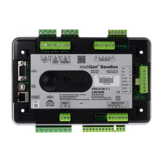
Page 55: Ig-Nt-Bb
7.4. IG-NT-BB 7.4.1. Schematics EXTENSION INTERCONTROLLER DISPLAY MODULES & MONITORING InteliGen BaseBox Order code: IG-NT-BB Made in EU, Czech Republic ( PROG. CNTRL.) 4XC2 LB 8 MAX 0,74 A Left to right: Pull down Bias / 120Ω / Pull up Bias / 120Ω / 120Ω ... -
Page 56: Terminals, Inputs And Outputs
7.4.2. Terminals, Inputs and Outputs Function Terminals Note Mains voltage L1,L2,L3, (N) 277 Ph-N or 480 Ph-Ph VAC (neutral not needed), max 600VAC *, CAT Bus voltage L1,L2,L3, (N) 277 Ph-N or 480 Ph-Ph VAC (neutral not needed), max 600VAC, CAT III Mains current L1k,L1l, L2k,L2l, 0 ÷... -
Page 57: Ig-Ntc-Bb
7.5. IG-NTC-BB 7.5.1. Schematics ( PROG. CNTRL.) 4XC2 LB 9 MAX 0,74 A Left to right: Pull down Bias / 120Ω / Pull up Bias / 120Ω / 120Ω Down: AI4 setting / AI3 setting / AI2 setting / AI1 SG OUT setting setting Current input 0-25mA... -
Page 58: Terminals, Inputs And Outputs
7.5.2. Terminals, Inputs and Outputs Function Terminals Note Generator voltage L1,L2,L3, (N) 3x120 / 277 Ph-N or 207 / 480 Ph-Ph VAC (neutral not needed), max 350 / 600VAC *, CAT III Mains/Bus voltage L1,L2,L3, (N) 3x120 / 277 Ph-N or 207 / 480 Ph-Ph VAC (neutral not needed), max 350 / 600VAC, CAT III Generator current... -
Page 59: Is-Ntc-Bb
* IG-MTU or IG-MTU-2-1 can be used for three wire systems, systems with separated Neutral or when galvanic separation between generator or mains voltage and controller is required. ** When more devices connected to RS485 bias resistor jumpers should be closed only on one of them. -
Page 60: Terminals, Inputs And Outputs
For more info see the chapter Resistance input 0-2400 Ω Speed Governor Output Boot jumper (upper one, rest of the jumpers is for internal use only) Left to right: Pull up Bias / 120Ω / Pull down Bias ... - Page 61 Modem, GSM modem or ECU (e.g. Cummins ModBus) or InteliVision RS485 (Display) ** A, B, COM Up to 3 IS-Displays (Remote display), up to 3 InteliVision 8 displays (remote display) or 3 InteliVision 5. Redirected RS232 (2) – see Basic settings: RS485 (2) ** A ,B ,COM RS485(2)conv.
-
Page 62: Im-Nt
Refer servicing To Qualified Service Personnel. InteliMains Order code: IM-NT GC Made in EU, Czech Republic www.comap.cz DONGLE For Use on a Flat Surface of a Type 1 Enclosure. Max. ambient temperature 70º C Use Copper Conductors Only Refer to installation instructions for torque values... -
Page 63: Terminals, Inputs And Outputs
7.7.2. Terminals, Inputs and Outputs Function Terminals Note Mains voltage L1,L2,L3, (N) 3x120 / 277 Ph-N or 207 / 480 Ph-Ph VAC (neutral not needed), max 350 / 600VAC*, CAT III Bus voltage L1,L2,L3, (N) 3x120 / 277 Ph-N or 207 / 480 Ph-Ph VAC (neutral not needed), max 350 / 600VAC, CAT III Mains current... -
Page 64: Im-Nt-Bb
MODULES & MONITORING InteliMains BaseBox Order code: MADE IN THE EU IM-NT-BB www.comap.cz ( PROG. CNTRL.) 4XC2 MAINS (BUS-L) VOLTAGE CURRENT 01–/0–5A MAX 0,74 A Left to right: Pull down Bias / 120Ω / Pull up Bias / 120Ω / 120Ω... -
Page 65: Terminals, Inputs And Outputs
7.8.2. Terminals, Inputs and Outputs Function Terminals Note Mains voltage L1,L2,L3, (N) 3x120 / 277 Ph-N or 207 / 480 Ph-Ph VAC (neutral not needed), max 350 / 600VAC*, CAT III Bus voltage L1,L2,L3, (N) 3x120 / 277 Ph-N or 207 / 480 Ph-Ph VAC (neutral not needed), max 350 / 600VAC, CAT III Mains current... -
Page 66: Im-Ntc-Bb
& MONITORING Inteli Mains BaseBox Order code: MADE IN THE EU IM-NTC-BB www.comap.cz MAINS (BUS-L) VOLTAGE CURRENT 01–/0–5A MAX 0,74 A Left to right: Pull down Bias / 120Ω / Pull up Bias / 120Ω / 120Ω... -
Page 67: General Jumper Settings
7.10. General Jumper Settings 7.10.1. Analog Inputs and Outputs This schematic shows general jumper settings of Analog Inputs and Outputs for all the controllers. Some components are available only for specific controllers (refer to the information above). 7.10.1.1. IS-NTC-BB (and IG-NT-BB, IG-NTC-BB, IM-NT-BB and IM- NTC-BB) Voltage measurement Binary inputs... -
Page 68: Speed Governor Output
Jumper settings for Analog Inputs and Outputs is the same for all the controllers. Not all analog inputs and outputs are available in all hardware modifications. AOUT COM is internally connected to controller 0 VDC power supply. 7.10.2. Speed Governor Output Pulse Width Modulation 500÷3000 Hz / 5V / 10mA max (default frequency 1200 Hz, may be SG OUT... -
Page 69: Measurement And Power Supply Wiring
8. Measurement and Power Supply Wiring 8.1. General To ensure proper function: • Use grounding terminals. • Wiring for binary inputs and analog inputs must not be run with power cables. • Analog and binary inputs should use shielded cables, especially when the length is more than 3 m. -
Page 70: Power Supply Fusing
AUTION Switchboard lightning strikes protection according standard regulation is expected!!! The maximum allowable current through the controller negative terminal is 3 to 8A (depends on the controller type and binary output load). 8.4. Power supply fusing Always use according fuse (1Amp or 2Amps) Binary outputs when connection controller, extension modules or T1A or T2A... -
Page 71: Voltage And Current Inputs
Take care to interference signal when one common speed pick-up is used for both Speed governor and Controller. When some problems occur: • check grounding connection from pick-up to controllers, disconnect ground connection to one of them. • use separate pick-up for Speed governor and Controller. Controller indicates "Sd Underspeed"... - Page 72 MAINS MAINS MAINS/ BUS GENERATOR VOLTAGE TERMINALS Principle of two transformers measuring - typical wiring for high voltage application spare of one transformer. URRENT MEASUREMENT WIRING AUTION Check measurement connections carefully! Failure is possible if phases are connected in wrong order (WrongPhSequence detected by the controller) but this is not detected if the phases are just rotated (i.e.
-
Page 73: Voltage Measurement Separation
8.6.2. Voltage measurement separation For optional separation of Mains/bus and generator voltage from the controller (e.g. on ships) use IG-MTU. 8.6.2.1. IG MTU Connect one or two IG-MTU units to separate generator and Mains/bus voltage from controller. Three wire mains Three wire mains and three wire genset or electric separation MAINS / BUS... - Page 74 The simplest arrangement covers all zones from the generator windings to the final circuits in the load network. I1k I1l I2k I2l I3k I3l Ink Inl This arrangement covers earth faults in the load network only. Ink Inl This arrangement necessary for restricted earth fault protection.
-
Page 75: Recommended Wiring
9. Recommended Wiring 9.1. SPtM application IGS-NT Installation Guide... -
Page 76: Spi Application
9.2. SPI application IGS-NT Installation Guide... -
Page 77: Mint Application
9.3. MINT application IGS-NT Installation Guide... -
Page 78: Single Phase Applications
9.4. Single Phase Applications There is no special archive file or software for single phase applications. Use standard archive. 9.4.1. Recommended wiring Generator (Mains) single phase voltage has to be connected to all three voltage terminals L1, L2, L3. Generator current has to be connected to L1k, L1l terminals only. Adjust setpoint Gener protect:Gen I unbal to 200%. -
Page 79: Intelimains - Mcb Application
9.5. InteliMains – MCB Application 9.5.1. BaseBox controller Load GEN-SET GROUP Mains V meas Bus V meas 2 3 4 5 6 7 8 9 10 11 12 Monitoring AI COM Analog control AOUT+ AOUT COM 9 10 11 12 + - L1k L1l L2k L2l L3k L3l LNk LNl 1 2 3 4 5 6 7 8 Aux Curr... -
Page 80: Controller With Built-In Display
9.5.2. Controller with built-in display Load GEN-SET GROUP Mains V meas Bus V meas Binary inputs Binary outputs L1k L1l L2k L2l L3k L3l LNk LNl Aux Curr Meas Binary Input MCB and Binary Output MCB O are the only compulsory BI FEEDBACK LOSE and BO in this application. -
Page 81: Intelimains - Mgcb Application
9.6. InteliMains – MGCB Application 9.6.1. BaseBox controller Load MGCB GEN-SET GROUP Mains V meas Bus V meas 2 3 4 5 6 7 8 9 10 11 12 Monitoring AI COM Analog control AOUT+ AOUT COM 9 10 11 12 + - L1k L1l L2k L2l L3k L3l LNk LNl 1 2 3 4 5 6 7 8 Binary Inputs MCB... -
Page 82: Controller With Built-In Display
9.6.2. Controller with built-in display Load MGCB GEN-SET GROUP Mains V meas Bus V meas Binary inputs Binary outputs L1k L1l L2k L2l L3k L3l LNk LNl Binary Inputs MCB and MGCB and Binary Outputs MCB O FEEDBACK FEEDBACK LOSE MGCB O are the only compulsory BI and BO in this application. -
Page 83: Intelimains - Btb Application
9.7. InteliMains – BTB Application 9.7.1. BaseBox controller GEN-SET GROUP GEN-SET GROUP BusL V meas BusR V meas 2 3 4 5 6 7 8 9 10 11 12 Monitoring AI COM Analog control AOUT+ AOUT COM 9 10 11 12 + - L1k L1l L2k L2l L3k L3l LNk LNl 1 2 3 4 5 6 7 8 Aux Curr... -
Page 84: Controller With Built-In Display
9.7.2. Controller with built-in display GEN-SET GROUP GEN-SET GROUP BusL V meas BusR V meas Binary inputs Binary outputs L1k L1l L2k L2l L3k L3l LNk LNl Aux Curr Meas Binary Input BTB and Binary Output BTB O are the only compulsory BI FEEDBACK LOSE and BO in this application. -
Page 85: Intelimains - Fdr Application
9.8. InteliMains – FDR Application 9.8.1. BaseBox controller Load Bus V meas Load V meas 2 3 4 5 6 7 8 9 10 11 12 Monitoring AI COM Analog control AOUT+ AOUT COM 9 10 11 12 + - L1k L1l L2k L2l L3k L3l LNk LNl 1 2 3 4 5 6 7 8 Aux Curr... -
Page 86: Controller With Built-In Display
9.8.2. Controller with built-in display Load Bus V meas Load V meas Binary inputs Binary outputs L1k L1l L2k L2l L3k L3l LNk LNl Aux Curr Meas Binary Input LCB and Binary Output LCB O are the only compulsory BI FEEDBACK LOSE and BO in this application. -
Page 87: Binary Input Wiring
9.9. Binary Input wiring Use min. 1 mm cables for wiring of binary inputs. The name and function or alarm type for each binary input Controller To microprocessor have to be assigned during the configuration. Binary inputs may be used in built-in PLC as well. Please refer to the manual of GenConfig for more information. -
Page 88: Controllers With High-Side Low-Side Switch
+PWR BOUT Controller Controller Battery 24V Battery 24V If +PWR BOUT is used, it increases power consumption of the controller. Outputs can provide steady current of up to 2A. Every single binary output can provide up to 0.5A of steady current unless the total current of group of outputs does not exceed 2A. 9.10.2. - Page 89 From From microprocessor microprocessor Internal Internal Binary outputs Binary outputs Battery 24V Battery 24V AUTION Both power supply sockets for binary outputs need to be connected to ensure proper function of binary outputs. Never use DC relays without protection diods! Low side or High side function of binary outputs can be chosen in configuration tool GenConfig in Modules tab.
-
Page 90: Examples Of Bi And Bo Wiring
9.11. Examples of BI and BO Wiring 9.11.1. Binary Outputs Wiring with I-RB16 9.11.2. Binary Inputs and Outputs Wiring IGS-NT Installation Guide... -
Page 91: Binary I/O On Is-Bin16/8
9.12. Binary I/O on IS-BIN16/8 9.12.1. Binary inputs on IS-BIN16/8 There are two groups of eight Binary inputs BI1 to BI8 and BI9 to BI16. Each group has a separate Common terminal COM1 and COM2. The Common terminal can be connected to positive or negative pole –... -
Page 92: Binary Outputs On Is-Bin16/8
9.12.2. Binary outputs on IS-BIN16/8 IS-BIN16/8 binary outputs are galvanically separated from IS-BIN16/8 power supply. It is necessary to connect plus 24 VDC (power supply ) to IS-BIN16/8 terminal according to following drawing. The maximum load values are 0.5 A / 36V for one output. BO 1 BO 2 BO 8... -
Page 93: Analog Input And Output Wiring
9.14. Analog Input and Output wiring Note that Analog Inputs and Outputs are available only in some types of hardware. For more information on technical data regarding supply, inputs, outputs etc. please refer to For jumper setting of Analog inputs please refer to the section Jumper settings. Resistive sensor on Analog input 3 and Resistive sensor with grounding on Analog Analog output wiring... -
Page 94: Analog Inputs On Is-Ain8
AI COM AI COM AOUT + AOUT + Internal Internal AOUT AOUT Battery 24V Battery 24V Tristate sensor (binary sensor with fail detection) on Analog input 3 Below 750Ω = Inactive Between 750Ω and 2400Ω = Active Below 10 Ω or Over 2400Ω = sensor failure (wire shorted or interrupted) 100R AI COM... - Page 95 • Thermocouple input • Voltage input Select sensor characteristic from the list or define user sensor characteristic in PC configuration tool. Resistor sensor input – two wire connection. Range 0 to 2400 ohms. Pt100, Pt1000, Ni100, Ni1000 D terminal is shielding Resistor sensor input –...
- Page 96 For 10V input voltage range connect external resistors R1, R2 and select sensor characteristic 10V. R1=10 kohm, R2=2,7 kohm. D terminal is shielding AUTION Thermocouples connected to IS-AIN8 hardware versions below 5.0 must be galvanically separated from the frame. If the thermocouples are connected to IS-AIN8, appropriate jumpers must be removed (see rear sticker).
-
Page 97: Outputs Refresh Rates
10. Outputs refresh rates There are the following refresh rates for binary and analog outputs. Type Refresh rate Analog Output on a controller 100ms Binary Output on a controller 100ms @ minimum puls length 20ms On demand if there is a „fast“ protection configured on this output Analog Output on an external 80ms times available modules for configuration (i.e. -
Page 98: External Modules Connection
11. External modules connection For all information on External modules please refer to the IGS-NT & ID-DCU Accessory Modules. 11.1. Lost Communication Protection Error message (e.g. SD BOUT2) appears on Controller screen when Binary input or output Address x is configured but corresponding unit is not recognized (no message is received from CAN bus). -
Page 99: Is-Ain8, Is-Bin8/16 Address Setting
• Input output address is displayed on the front panel LED’s • Use PC configuration tool to configure controller according external modules setting IS-BIN16/8 module has two separate CAN1 addresses for binary inputs Group 1, Group 2 and binary outputs Group (total three addresses). The CAN1 address for BI Group 1 and for BO Group 2 can be adjusted on the IS-BIN16/8. -
Page 100: Igs-Ptm And Igl-Ra15
Always check the number and placement of terminating resistors in the CAN bus line, only correct wiring ensures reliable operation! Resistors must be placed at either end of the line (see picture), and correct number of resistors must be used! Correct number can be checked using ohmmeter - when power supply for ALL devices on the CAN bus line (including third party, e.g. -
Page 101: Connection Of Ecu On Can1 With Other Modules Connected
(optional) (optional) (optional) IS-AIN8 1 IS-BIN 16/8 IGL-RA15 IGS-PTM I-CB Addr. In1 out1 Addr.:1 CAN 1 CAN 1 CAN 1 CAN 1 CAN 1 CAN 1 CAN 2 Controller 1 CAN 1 CAN 2 Addr.:1 CAN 2 CAN 2 I-LB Controller 2 IG-IB Addr.:2... -
Page 102: I-Cb Wiring And Configuration
ECU communicating over the CAN bus is connected to CAN1 port of the controller and other ComAp modules can be connected to this CAN bus as well. For detailed description of connection of various ECUs refer to ComAp Electronic Engines Support manual. -
Page 103: Communications
12. Communications 12.1. Available Communication Ports Hardware Type Communication Ports RS232(1) RS485(1) – multipurpose IG-NT CAN1 CAN2 RS232(1) RS485(1) – multipurpose IG-NTC RS232(2) RS485(2) – multipurpose CAN1 CAN2 RS232(1) RS485(1) – display dedicated IG-NT-BB CAN1 CAN2 RS232(1) ... -
Page 104: Possible Connections Per Port
12.2. Possible Connections per Port Port Type On Number of Available Connections Hardware Connections RS232(1) InteliVision 8 Modbus terminal Modem RS485(1) IG-NT-BB InteliVision 8 IG-NTC-BB InteliVision 5 IM-NT-BB IG-Display IM-NTC-BB RS485(1) IS-NT-BB InteliVision 8 IS-NTC-BB InteliVision 5 IS-Display RS485(1) IG-NT InteliVision 8 IG-NTC IM-NT... -
Page 105: Can Bus
13. CAN Bus 13.1. CAN bus Tx, Rx LED indication Tx and Rx LED is connected directly to Tx and Rx signal. Status Fast flashing – data transfer Communication is OK CAN bus is interrupted Continuous light Continuous light H – L Short connection Fine flashing Dark... -
Page 106: Wiring Examples
RS485 BUS TOPOLOGY See the website www.can-cia.org for information about the CAN bus, specifications, etc. 13.2.1. Wiring examples 1. For shorter distances (all network components within one room) – picture 1 interconnect A and B; shielding connect to PE on controller side 2. - Page 107 1 – ICTURE SHORTER DISTANCES ALL NETWORK COMPONENTS WITHIN ONE ROOM 2 – ICTURE LONGER DISTANCES CONNECTION BETWEEN ROOMS WITHIN ONE BUILDING 3 – ICTURE SURGE HAZARD CONNECTION OUT OF BUILDING IN CASE OF STORM ETC IGS-NT Installation Guide...
-
Page 108: Dongle Installation
14. Dongle installation Dongle for load sharing, power management and additional PLC functions should be installed from the rear side of the controller under the rubber plug. Insert dongle so the dongle label remains visible as shown on the picture. GEN VOLT MAINS VOLT DISPLAY CAN1... -
Page 109: Sensors
15. Sensors 15.1. Sensor fail detection (FLS) If the measured resistance, voltage or current on an analog input gets out of valid range, the sensor fail will be detected and a sensor fail message will appear in the alarmlist. The valid range is defined by the most-left (R ) and most-right (R ) points of the sensor characteristic... - Page 110 In this dialog you can choose from available sensors or define your own (click on New). All sensor curves in this dialog can be found in: c:\Documents and Settings\All Users\Dokumenty\ComAp PC Suite\Curves\ (for Windows XP) c:\Users\Public\Documents\ComAp PC Suite\Curves\ (for Windows 7) You can choose “Electronic”...
-
Page 111: Regulation Loops
16. Regulation loops There are following regulation loops bulit-in in the controller. All of them are PI type except angle loop, which is P type. The frequency loop is active in the first phase of synchronization when the generator frequency is regulated to match the mains/bus frequency. -
Page 112: Pi Regulation Adjustment
following value: 235/230 = 1.02174*220 = 225V. This enables usage of transformators between the measurement terminals. This regulation loop is active when single gen-set is running in parallel with the mains. This regulation loop is also active when multiple gen-sets are Cos-phi loop running in parallel with mains in BASEPF mode i.e. - Page 113 Typical responses of a PI regulator For manual tunning of a control loop use following method: 1. Set both the I-factor and P-factor to 0. 2. Increase the P-factor slightly until the system starts to oscillate. 3. Adjust the P-factor back to approx. one half of the value where the oscillations started.
-
Page 114: Speed Governor And Avr General Settings
17. Speed governor and AVR general settings 17.1. Sync/load control adjustment Hint: Use isochronous speed governor. Two wire shielded connection from IGS-NT SPEED GOVERNOR output (SG OUT, SG COM) to Speed governor auxiliary input is recommended. A full range change of the IGS-NT speed governor output (from SpeedGovLowLim to SpeedGovHiLim) should cause 5-10% change of the engine speed (SpeedGovLowLim ~ 95% RPM , Speed gov bias ~ 100% RPM... -
Page 115: Load Control Adjustment
2) Set the engine RPM by speed trim on speed governor or by Speed gov bias and SpeedGovLowLim and SpeedGovHiLim to reach Nominal frequency. 3) To start synchronizing press GCB ON/OFF button. GCB LED starts to flash to indicate synchronization. To stop synchronization press again GCB ON/OFF . Slip control adjusting: 4) Adjust Freq gain to unstable speed control and decrease value by 30 % to insure stable performance. -
Page 116: Volt/Pf Control Adjustment
MAINS LOAD P > 0 Import P > 0 Consumption P> 0 Generation Q> 0 Import Q> 0 Consumption Q> 0 Generation Cos > 0 L Cos < 0 L Cos > 0 Cos < 0 L Cos > 0 L Consumption Export P Consumption... -
Page 117: Voltage Control Adjustment
AVRi outputs can be connected as symmetric: OUT1-OUT2 or asymmetric OUT1-OCOM or OUT2-OCOM. • Potentiometer on the AVRi defines maximum OUT1, OUT2 voltage range. • Use symmetric (OUT1,OUT2) AVRi output to connect the AVRi to AVR auxiliary voltage input. • Use asymmetric output if an external AVR potentiometer has to be replaced with AVRi. -
Page 118: Pf Control Adjustment
7) When gen-set is running unloaded increase carefully Voltage gain to unstable point and then decrease value by 30 % to insure stable performance. 8) Adjust Voltage int (usually setting to 100% gives optimal performance). Hint: To judge optimal adjusting induce generator voltage jumps by AVR DCout bias change or by Nominal voltage change. -
Page 119: Speed Governor Interface List
Electronic Control Units (Electronic engines) with CAN data bus. There are several possibilities to connect CAN bus interface between Electronic engine and ComAp controller. Refer to ComAp Electronic Engines Support manual. 18.1.1. Communication Bridge Unit I-CB unit is an interface between Controller and Electronic engine. Following I-CB types are available: For more details see I-CB-ICBEdit-1.1.pdf manual. - Page 120 Sync/Load ctrl: Speed gov bias = 2,7V SpeedRegChar = SG COM POSITIVE SG OUT VoutR SpeedGovLowLim = 0V SpeedGovHighLim = 6V ComAp Sync/Load ctrl: Speed gov bias = 5,1V SpeedRegChar = SG COM POSITIVE SG OUT Vout SpeedGovLowLim = 0,0V...
- Page 121 Pay attention to the connector and jumper orientation. Caterpillar Signal Converter It is not necessary to use Caterpillar Signal Converter with controller from NT family (InteliGen and InteliSys ). Use direct PWM output instead. Sync/Load ctrl: SG COM Speed gov bias = 5,10 V SG OUT SpeedRegChar = POSITIVE...
- Page 122 Sync/Load ctrl: SG COM Speed gov bias = 2,50 V SG OUT SpeedRegChar = VoutR POSITIVE SpeedGovLowLim = 0V SpeedGovHiLim = 5V SG COM Sync/Load ctrl: SG OUT Speed gov bias = 5,00 V VoutR SpeedRegChar = POSITIVE Sync/Load ctrl: Speed gov bias = 3,50 V SG OUT SpeedRegChar =...
- Page 123 SG COM Sync/Load ctrl: SG OUT Speed gov bias = 5,00 V VoutR SpeedRegChar = NEGATIVE Sync/Load Ctrl: Speed Gov Bias = 5.00 V SG COM SpeedGovChar = SG OUT NEGATIVE VoutR SpeedGovLowLim = 4 V SpeedGovHiLim = 6 V Sync/Load ctrl: SG COM Speed gov bias = 5,00 V...
- Page 124 SG COM Sync/Load ctrl: SG OUT Speed gov bias = 3,1 V VoutR SpeedRegChar = POSITIVE SpeedGovLowLim = 6,5 V SpeedGovHiLim = 0,0 V Actuator 16 COM SG COM Sync/Load ctrl: 15 ± SG OUT Speed gov bias = 5,00 V VoutR SpeedRegChar = POSITIVE...
- Page 125 Sync/Load ctrl: SG OUT 8 ( 0 to 10 VDC) Speed gov bias = 4,90 V SG COM Vout SpeedRegChar = POSITIVE SpeedGovLowLim = 0V Pay attention to the connector and jumper orientation. SpeedGovHiLim = 10V DEUTZ Plug F Sync/Load ctrl: SG OUT 24 (0, 5 to 4, 5 VDC ) Speed gov bias = 2,50 V...
- Page 126 SG COM Sync/Load ctrl: SG OUT Speed gov bias = 4,00 V VoutR SpeedRegChar = POSITIVE DGC-2007 ComAp Sync/Load Ctrl: Speed Gov Bias = 5.1 V SG + SpeedGovChar = Vout AO COM POSITIVE SpeedGovLowLim = 0 V SpeedGovHiLim = 10 V...
-
Page 127: Avr Interface List
19. AVR Interface List Read carefully AVR instructions before connecting to controller! Basler: APR 63-5, AEC 63-7, KR-FX, KR-FFX AVRi trim to minimum From 230/400VAC counter clockwise. generator 18VAC AVRi 0VAC TRANS AVRI OUT Volt/PF ctrl: AVRi+ AVR DCout bias = 50% OCOM AVRI COM VoltRegChar = POSITIVE... - Page 128 STAMFORD MX 341 AVRi trim to minimum From 230/400VAC generator 18VAC counter clockwise. AVRi 0VAC TRANS AVRI OUT Volt/PF ctrl: AVRi+ OCOM AVRI COM AVR DCout bias = 50% AVRi- OUT1 VoltRegChar = POSITIVE Hint: Disconnect the droop CT (terminal S1 & S2) and short the droop CT leads short the terminal S1,S2 on the AVR Stamford AS480...
- Page 129 Leroy Somer: R 129 From AVRi trim to minimum 230/ 400VAC generator 18VAC AVRi 0 VAC counter clockwise. TRANS AVRI OUT AVRi+ Volt/PF ctrl: OCOM AVRI COM AVR DCout bias = 50% AVRi - OUT 1 VoltRegChar = POSITIVE AVRi output is connected instead Remote voltage trimmer 470 ohm to terminal J2.
- Page 130 Leroy Somer: R 230 230/ 400VAC from generator AVRi 0 VAC TRANS AVRI OUT AVRi+ AVRI COM OUT2 AVRi - OUT1 Module R726 is not required. AVRi trim to minimum counter clockwise. Volt/PF ctrl: AVR DCout bias = 50% VoltRegChar = POSITIVE IGS-NT Installation Guide...
- Page 131 Leroy Somer: R 230 AVRi trim to minimum From 230/400VAC generator 18VAC AVRi counter clockwise. 0VAC TRANS AVRI OUT Volt/PF ctrl: AVRi+ OUT2 AVRI COM AVR DCout bias = 50% AVRi- OUT1 VoltRegChar = POSITIVE Remove Link J4 and replace through R500 Primary voltage setting with resistors connected: 230V Hint: Disconnect one wire (OUT 1), set voltage on running Generator to U...
- Page 132 Leroy Somer: R 250 From AVRi trim to minimum 230/ 400VAC generator 18VAC AVRi 0 VAC counter clockwise. TRANS AVRI OUT AVRi+ VoltRegChar = POSITIVE OCOM AVRI COM AVRDCout bias = 50% AVRi - OUT1 Mecc Alte Spa: U.V.R.6 AVRi trim to maximum From 230/400VAC generator...
- Page 133 AVRi trim = 1/16 from minimum ( =6,25% => max. = 2,5V). Volt/PF ctrl: AVR DCout bias = 50% VoltRegChar = POSITIVE The Vext input (connector CN1 – terminals 10 and 11) permits analogical remote control of output voltage with a programmable variation range of up to ±10% (parameter 16, by default the setting is ±5%) with respect to the value set.
- Page 134 Piller AVRi trim to minimum From 230/400VAC generator 18VAC counter clockwise. AVRi 0VAC TRANS AVRI OUT Volt/PF ctrl: AVRi+ OUT2 AVRI COM AVR DCout bias = 39% AVRi- OUT1 VoltRegChar = POSITIVE AVRi output is connected instead Remote voltage trimmer 100Kohm. Catterpillar VR6, VR3F AVRi trim to minimum From...
- Page 135 From AVRi trim to minimum 230/ 400VAC generator 18VAC AVRi 0 VAC counter clockwise TRANS AVRI OUT AVRi+ Volt/PF ctrl: OUT2 AVRI COM AVR DCout bias = 50% AVRi- OUT1 VoltRegChar = POSITIVE Newer Leroy Somer From AVRi trim to minimum 230/ 400VAC generator 18VAC...
- Page 136 From 230/ 400VAC generator 18VAC AVRi Volt/PF ctrl: 0 VAC TRANS AVR DCout bias = 50% AVRI OUT VoltRegChar = POSITIVE AVRi+ OUT2 AVRI COM AVRi- OUT1 MarelliGenerators MARK 5 (M16FA655A) From AVRi trim to ¼ position 230/400VAC IG- AVRi generator 18VAC 0VAC...
- Page 137 From Volt/PF ctrl: 230/400VAC IG- AVRi generator 18VAC AVR DCout bias = 50% 0VAC TRANS VoltRegChar = POSITIVE AVRI OUT AVRi+ OUT2 AVRI COM AVRi- OUT1 SINCRO AVR BL4 or AVR BL3 From AVRi trim to middle position 230/400VAC IG- AVRi generator 18VAC 0VAC...
-
Page 138: Technical Data
20. Technical Data 20.1. Power supply Controller IS-Display IG-Display InteliVision InteliVision Voltage 8-36V DC 8-36V DC 8-36V DC 8-36V DC 8-36V DC supply Consumption 0,4A at 0,3A at 0,4A at 1A at 8VDC 0.7 A at depends on 8VDC 8VDC 8VDC 8VDC supply... -
Page 139: Dimensions And Weight
Storage temperature IS-NT-BB -40..+80 Flash memory data retention time 10 years Protection front panel (built-panel) IP65 Humidity 95% without condensation IEC/EN 60068-2-30 Standard conformity Low Voltage Directive EN 61010-1:95 +A1:97 Electromagnetic Compatibility EN 50081-1:94 (EN 61000-6-3) EN 50081-2:96 (EN 61000-6-4) EN 50082-1:99 (EN 61000-6-1) EN 50082-2:97 (EN 61000-6-2) Vibration... -
Page 140: Voltage Inputs - Ig/Is-Nt And Modifications
Max. peak current from CT 150 A / 1s 150 A / 1s Max. short term current 12 A (for 30s) 2,4 A / 12 A (for 30s) Max. continuous current 1 A / 5 A Voltage inputs – IG/IS-NT and modifications 20.4.2. -
Page 141: Analog Inputs
Maximum switching 36 VDC 36 VDC 36 VDC voltage 20.6. Analog inputs Not electrically separated Number of inputs 3 / 0 / 4 unipolar ( IG-NT(x), IG-NT(x)-BB/ IM-NT / IS-NT-BB,IS-NTC-BB ) Resolution 10 bits Jumper selectable range V, ohm, mA 2500 ... -
Page 142: Can Bus Interface
20.9.3. CAN bus interface Galvanically separated Maximal CAN bus length 200m Speed 250kBd Nominal impedance 120 Cable type twisted pair (shielded) Following dynamic cable parameters are important especially for maximal 200 meters CAN bus length and 32 iS-COM units connected: Nominal Velocity of Propagation min. -
Page 143: Ig-Avri Trans/Lv
Mechanical dimensions: 96 x 27 x 43 mm , DIN rail (35 mm) mounted 20.11.1. IG-AVRi Trans/LV Primary voltage 1: 230-277 VAC 230 VAC – 20% Absolute low limit: Absolute high limit: 277 VAC + 20% Primary voltage 2: 400-480 VAC 400 VAC –... -
Page 144: Analog Inputs
20.12.3. Analog inputs Not electrically separated Number of inputs Resolution 10 bits 0 – 250 Maximal resistance range 0 – 100 mV Maximal voltage range 0 – 20 mA Maximal current range 1 % 2 out of measured value Resistance measurement tolerance 1,5 % ... -
Page 145: I-Aout8
Each analog input can be software configured to: Measuring range Accuracy From Resistance ± 0,5 % 2400 ± 1,0 % Current Passive 0 / 4 mA 20 mA ± 0,5 % Active 4 mA 20 mA ±... -
Page 146: Binary Inputs
Electromagnetic Compatibility EN 50081-1:94 (EN 61000-6-3) EN 50081-2:96 (EN 61000-6-4) EN 50082-1:99 (EN 61000-6-1) EN 50082-2:97 (EN 61000-6-2) 20.15.1. Binary inputs Galvanically separated two groups Number of inputs 8 + 8 Input resistance 3 k Input voltage range 0-36 VDC Input voltage level for open contact 8 to Power supply VDC Input voltage level for close contact... -
Page 147: Dimensions And Weight
Operating temperature -20..+70 Storage temperature -30..+80 Protection front panel IP65 20.16.3. Dimensions and weight Dimensions 180x120x55mm Weight 950g 20.16.4. Horn output Maximum current Maximum switching voltage 36 VDC 20.17. I-CB, I-CR 20.17.1. Power supply Voltage input 8-36V DC Consumption 0.1A depend on power supply 20.17.2. -
Page 148: Rs232 Interface
20.17.5. RS232 interface Maximal distance Speed p to 19.2kbps (depends on ECU type connected) 20.18. I-LB Voltage supply -36V DC Consumption ,1A depend on supply voltage Operating temperature -30..+70 Mechanical dimensions: 5 x 96 x 43 mm , DIN rail (35 mm) mounted S232, RS422, RS485, (USB –... -
Page 149: Ig-Mtu-2-1
Primary/secondary Phase shift 1° Operating temperature -30..+70 20.22. IG-MTU-2-1 Primary voltage Ph-Ph x600 VAC / 50Hz (3x720 VAC / 60 Hz) Secondary voltage Ph-N x 173 V AC ( 3x208 VAC / 60 Hz) , 5 VA Mechanical dimensions: 55 x 95 x 60 mm , DIN rail (35 mm) mounted Primary/secondary Phase shift 1°...
Need help?
Do you have a question about the IGS-NT Series and is the answer not in the manual?
Questions and answers