Table of Contents
Advertisement
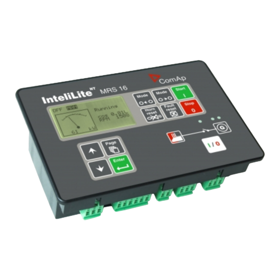
NT
InteliLite
InteliLite NT
Modular Gen-set Controller
Compact Controller for Single Operating Gen-sets
(IL-NT MRS10/11/15/16 unit)
SW version 1.5, September 2009
Copyright © 2009 ComAp s.r.o.
Written by Petr Novák
Prague, Czech Republic
®
MRS
ComAp, spol. s r.o.
Kundratka 2359/17, 180 00 Praha 8, Czech Republic
Tel: +420 2 66316661, Fax: +420 2 66316647
E-mail: info@comap.cz,
Reference Guide
www.comap.cz
Advertisement
Table of Contents


Need help?
Do you have a question about the InteliLite NT MRS and is the answer not in the manual?
Questions and answers