Table of Contents
Advertisement
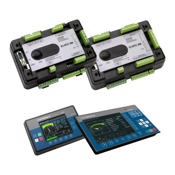
Compact Controller for Stand-by and Parallel Operating Gen-sets
Inteli New Technology
Modular Gen-set Controller
IG-NT GC, IG-NTC GC, IS-NT-BB,IG-NT-BB, IG-NTC-BB, IS-NTC-BB
Software version IGS-NT-BC-1.2.0, January 2019
ComAp a.s.
U Uranie
1612/14a, Prague 7, Czech Republic
Tel: +420
246 012
E-mail: info@comap-control.com, www.comap-control.com
Bank Controller
REFERENCE GUIDE
111, Fax:
+266 31 66 47
Advertisement
Table of Contents

Related Manuals for ComAp IG-NT GC


Summary of Contents for ComAp IG-NT GC
- Page 1 Compact Controller for Stand-by and Parallel Operating Gen-sets Inteli New Technology Modular Gen-set Controller Bank Controller IG-NT GC, IG-NTC GC, IS-NT-BB,IG-NT-BB, IG-NTC-BB, IS-NTC-BB Software version IGS-NT-BC-1.2.0, January 2019 REFERENCE GUIDE ComAp a.s. U Uranie 1612/14a, Prague 7, Czech Republic Tel: +420...
-
Page 2: Table Of Contents
Setpoints ................................58 List of possible events ............................59 Controller configuration and monitoring ......................60 Direct connection to the PC ......................... 60 GenConfig functions ............................. 60 InteliMonitor ..............................61 IGS-NT-BC, SW Version 1.2.0, ©ComAp – January 2019 IGS-NT-BC-1.2.0 Reference Guide.PDF... - Page 3 Table of setpoints ............................64 Table of values ............................151 Table of binary input functions ........................183 Table of analog input functions ........................223 Table of binary output functions ......................... 225 IGS-NT-BC, SW Version 1.2.0, ©ComAp – January 2019 IGS-NT-BC-1.2.0 Reference Guide.PDF...
-
Page 4: Document Information
Pressing F1 in the GenConfig and InteliMonitor setpoint, values or configuration window will open the help with the context of currently selected setpoint, value and binary input or output function. IGS-NT-BC, SW Version 1.2.0, ©ComAp – January 2019 IGS-NT-BC-1.2.0 Reference Guide.PDF... -
Page 5: Available Related Documentation
Thorough description of accessory modules for IGS-NT family, technical data, information about IGS-NT & ID-DCU Accessory Modules 07-2014.pdf installation of the modules, how to connect them to controller and set them properly. IGS-NT-BC, SW Version 1.2.0, ©ComAp – January 2019 IGS-NT-BC-1.2.0 Reference Guide.PDF... -
Page 6: General Guidelines
Note: ComAp believes that all information provided herein is correct and reliable and reserves the right to update at any time. ComAp does not assume any responsibility for its use unless otherwise expressly undertaken. -
Page 7: Dangerous Voltage
The following instructions are for qualified personnel only. To avoid personal injury do not perform any action not specified in this User guide !!! Clarification of notation This type of paragraph points out details to help user installation/configuration. IGS-NT-BC, SW Version 1.2.0, ©ComAp – January 2019 IGS-NT-BC-1.2.0 Reference Guide.PDF... - Page 8 This type of paragraph indicates things, procedures, adjustments, etc. which demand a high level of attention, otherwise personal injury or death may occur. XAMPLE This type of paragraph indicates examples of usage for illustrational purposes. IGS-NT-BC, SW Version 1.2.0, ©ComAp – January 2019 IGS-NT-BC-1.2.0 Reference Guide.PDF...
-
Page 9: Available Firmware And Archive Sets
For IG-NT-GC and IG-NTC-GC For IG-NT-BB and IG-NTC-BB For IS-NT-BB and IS-NTC-BB IG-NT-GC-3.3.0 IG-NT-BB-3.3.0 IS-NT-3.3.0 Archives (*.ant) For IG-NT(C) GC For IG-NT-BB and IG-NTC-BB For IS-NT-BB and IS-NTC-BB IG-GC-MINT-BC-3.3.0 IG-BB-MINT-BC-3.3.0 IS-MINT-BC-3.3.0 IGS-NT-BC, SW Version 1.2.0, ©ComAp – January 2019 IGS-NT-BC-1.2.0 Reference Guide.PDF... -
Page 10: General Description Of System With Bank Controller
Power management works among all the gen-sets in the system to ensure the equal run hours and the most efficient combination of running gen-sets to cover the actual load demand and the requested load reserve. IGS-NT-BC, SW Version 1.2.0, ©ComAp – January 2019 IGS-NT-BC-1.2.0 Reference Guide.PDF... -
Page 11: Installation
InteliSys NT controllers with standard firmware and special “MINT-BC” archive. The general rules for CAN bus wiring remain valid, i.e. the total length of the CAN bus must not exceed 200m (250kbps) or 800m (50kbps). IGS-NT-BC, SW Version 1.2.0, ©ComAp – January 2019 IGS-NT-BC-1.2.0 Reference Guide.PDF... -
Page 12: Power Lines Wiring
If the function LBI: BCB feedback is configured at some input the controller assumes the BCB is used. If this function is left unconfigured then connection without BCB is assumed. IGS-NT-BC, SW Version 1.2.0, ©ComAp – January 2019 IGS-NT-BC-1.2.0 Reference Guide.PDF... - Page 13 GC = Gen-set controller IG-NT, IS-NT BC = Bank controller IS-NT Figure: Power line wiring of system with the BCB Figure: Power line wiring of system without the BCB IGS-NT-BC, SW Version 1.2.0, ©ComAp – January 2019 IGS-NT-BC-1.2.0 Reference Guide.PDF...
-
Page 14: Ac Measurement
Common bus voltage, 3phase, required • Bank current, 3phase, recommended Following AC values are to be measured in systems without BCB: • Bank bus voltage, 3phase, recommended • Bank current, 3phase, optional IGS-NT-BC, SW Version 1.2.0, ©ComAp – January 2019 IGS-NT-BC-1.2.0 Reference Guide.PDF... - Page 15 EXTENSION INTERC ONTR OLLER D ISPLAY M OD ULES & M ONITORI NG IS-NT BANK CONTROLLER LB 9 GENERATOR CURRENT TO THE GENSETS Figure: AC measurement with the BCB IGS-NT-BC, SW Version 1.2.0, ©ComAp – January 2019 IGS-NT-BC-1.2.0 Reference Guide.PDF...
-
Page 16: Bcb Control And Synchronizing
BCB is not used. See the chapter Installation for information about proper wiring of the site with or without BCB. IGS-NT-BC, SW Version 1.2.0, ©ComAp – January 2019 IGS-NT-BC-1.2.0 Reference Guide.PDF... - Page 17 In automatic mode the breaker is controlled automatically, in manual mode by the button on the controller front panel or InteliVision. IGS-NT-BC, SW Version 1.2.0, ©ComAp – January 2019 IGS-NT-BC-1.2.0 Reference Guide.PDF...
-
Page 18: Functions
When gen-set is unloaded (see GCB open level or GCB open del) opens the output GCB CLOSE/OPEN. 9) The Running hours balancing or Load demand engines swap can be activated in power management. IGS-NT-BC, SW Version 1.2.0, ©ComAp – January 2019 IGS-NT-BC-1.2.0 Reference Guide.PDF... -
Page 19: Active And Reactive Power Control In The System With Bank Controller
The function is based on the load evaluation in order to provide enough of available running power. Since it allows the system to start and stop gen-sets based on the load demand, it can vastly improve the system IGS-NT-BC, SW Version 1.2.0, ©ComAp – January 2019 IGS-NT-BC-1.2.0 Reference Guide.PDF... - Page 20 The actual priority of each bank can be changed by the power management to equalize the run hours of the banks Pwr management: #PriorAutoSwap = RUN HOURS EQU. (each bank counts IGS-NT-BC, SW Version 1.2.0, ©ComAp – January 2019 IGS-NT-BC-1.2.0 Reference Guide.PDF...
- Page 21 Stopping sequence sequence Stopped and ready Bank 2 Running, loaded to PM Bank 1 Running, loaded BO Syst res OK Time Figure: Power management based on absolute load reserve IGS-NT-BC, SW Version 1.2.0, ©ComAp – January 2019 IGS-NT-BC-1.2.0 Reference Guide.PDF...
- Page 22 Important setpoint: Pwr management: #PriorAutoSwap The Automatic priority swapping function does not change the setpoint Pwr management: Priority. The function sets the order of banks by virtual values “engine priority”. IGS-NT-BC, SW Version 1.2.0, ©ComAp – January 2019 IGS-NT-BC-1.2.0 Reference Guide.PDF...
- Page 23 #MinRunPower 1 considered if LBI MinRun power 1 activated • #MinRunPower 2 considered if LBI MinRun power 2 activated • #MinRunPower 3 considered if LBI MinRun power 3 activated IGS-NT-BC, SW Version 1.2.0, ©ComAp – January 2019 IGS-NT-BC-1.2.0 Reference Guide.PDF...
- Page 24 2. The BTB position is detected by the controllers 2 and 3. The reason, why there are 2 controllers used for detection of the BTB position, is to have a backup source of the group link information if the primary source (controller) is switched off. IGS-NT-BC, SW Version 1.2.0, ©ComAp – January 2019 IGS-NT-BC-1.2.0 Reference Guide.PDF...
-
Page 25: Load Shedding
LdShed stage 3 AutoLd recon If no Load Shedding outputs are configured, there is no record to history and no scrren timer indication of the activity of this function. IGS-NT-BC, SW Version 1.2.0, ©ComAp – January 2019 IGS-NT-BC-1.2.0 Reference Guide.PDF... -
Page 26: Circuit Breakers Operation Sequence, Cb Fail Detection
CB fdb neg – negative CB feedback binary input. Used for increasing the reliability of CB status evaluated by the controller. In case that it is not configured, negative value of CB fdb is calculated internally within the controller. IGS-NT-BC, SW Version 1.2.0, ©ComAp – January 2019 IGS-NT-BC-1.2.0 Reference Guide.PDF... - Page 27 BO: CB ON coil BI: CB fdb BI: CB fdb neg When closing the CB, the CB status LBO switches over only when both feedbacks are in correct position BO: CB status IGS-NT-BC, SW Version 1.2.0, ©ComAp – January 2019 IGS-NT-BC-1.2.0 Reference Guide.PDF...
- Page 28 CB fail – If any inconsistence between the two feedback signals is detected, CB fail is issued. BI: CB fdb neg = 1 BO: CB status = 0 BO: CB fail IGS-NT-BC, SW Version 1.2.0, ©ComAp – January 2019 IGS-NT-BC-1.2.0 Reference Guide.PDF...
- Page 29 BI: CB fdb During CB opening the CB status LBO is deactivated with change of BI: CB fdb neg the first feddback status BO: CB status IGS-NT-BC, SW Version 1.2.0, ©ComAp – January 2019 IGS-NT-BC-1.2.0 Reference Guide.PDF...
- Page 30 BO: CB status Other CB fail reasons: When the BO CB close/open is in steady state and CB feedback is changed, the CB fail is detected immediately (no delay). IGS-NT-BC, SW Version 1.2.0, ©ComAp – January 2019 IGS-NT-BC-1.2.0 Reference Guide.PDF...
-
Page 31: Remote Alarm Messaging
SMS-GSM: This option sends a short text message (SMS) containing the actual Alarmlist contents to the recipient's mobile phone via the GSM modem. The channel address must contain complete telephone number of the recipient's mobile phone. IGS-NT-BC, SW Version 1.2.0, ©ComAp – January 2019 IGS-NT-BC-1.2.0 Reference Guide.PDF... -
Page 32: Controller Redundancy
Redundant systems using binary signals It is not possible to use this redundancy system since correct function of the ccontroller depends on CAN bus communication and thus CAN redundancy should be always used. IGS-NT-BC, SW Version 1.2.0, ©ComAp – January 2019 IGS-NT-BC-1.2.0 Reference Guide.PDF... -
Page 33: Force Value - Step By Step Guide
(e.g. there are two different periods during the day when Export limit given by distribution network is required or not). ARNING IGS-NT-BC, SW Version 1.2.0, ©ComAp – January 2019 IGS-NT-BC-1.2.0 Reference Guide.PDF... - Page 34 Integer 16 to a setpoint with dimension hours and which is as well Integer 16). You may use PLC block Convert to change the dimension and range if needed. IGS-NT-BC, SW Version 1.2.0, ©ComAp – January 2019 IGS-NT-BC-1.2.0 Reference Guide.PDF...
-
Page 35: Values For Continuous Writing From External Sources
Each timer channel can be activated only once within a single day. The activation time and duration of each channel is adjustable (both as hh:mm). IGS-NT-BC, SW Version 1.2.0, ©ComAp – January 2019 IGS-NT-BC-1.2.0 Reference Guide.PDF... - Page 36 0:00, timer duration 0:30 min. 3. The setpoint Timer settings:TimerChannel 2 is adjusted to "once" mode, starting date/time 1.5.2010 at 01:00, timer duration 3:00 hrs. IGS-NT-BC, SW Version 1.2.0, ©ComAp – January 2019 IGS-NT-BC-1.2.0 Reference Guide.PDF...
-
Page 37: History Related Functions
Period of time stamping may be adjusted from 1 to 240 minutes. Beware of History flooding by to many Time Stamps (vital information may be overwritten). IGS-NT-BC, SW Version 1.2.0, ©ComAp – January 2019 IGS-NT-BC-1.2.0 Reference Guide.PDF... -
Page 38: User Buttons
Summer Time Mode function may be enabled and disabled by user. It is possible to set if the controller is located in the northern or southern hemisphere as well. SummerTimeMode implemented in ComAp controllers is based on CET summer time which means: •... -
Page 39: Remote Control Function
It is possible to select any logical Binary Output function for one of the outputs of VPIO module. Inputs on VPIO module work the same way as standard input of the controller (i.e. it can be assigned function and protection). IGS-NT-BC, SW Version 1.2.0, ©ComAp – January 2019 IGS-NT-BC-1.2.0 Reference Guide.PDF... -
Page 40: Shared Inputs And Outputs
Module SHBIN (2) is not inserted SHBIN (3) SHBOUT (3) Not Received Module SHBIN (3) is not inserted Figure: Principal Scheme (same for shared Binary I/O and shared Analogue I/O IGS-NT-BC, SW Version 1.2.0, ©ComAp – January 2019 IGS-NT-BC-1.2.0 Reference Guide.PDF... - Page 41 SHBOUT1). Controller sends Shared Binary Outputs each 100ms if there are any changes in any bit position. If there are no changes, controller sends the information with period 1s. IGS-NT-BC, SW Version 1.2.0, ©ComAp – January 2019 IGS-NT-BC-1.2.0 Reference Guide.PDF...
-
Page 42: Distributed Binary Inputs And Outputs
(interGen-set CAN). It means that these signal can be distributed either between the bank controllers and other controller connected to CAN-A or between all the gen-set controllers connected to CAN-B. DISTBIN and DISTBOUT function is conditioned by IGS-NT-LSM+PMS dongle. IGS-NT-BC, SW Version 1.2.0, ©ComAp – January 2019 IGS-NT-BC-1.2.0 Reference Guide.PDF... -
Page 43: Modbus Reading And Writing
Modbus protocol between FW versions or branches. Value, Setpoint, Alarm state Communication object number Standard Modbus register number User Modbus register number Select type Select object User MODBUS function is not available for IM-NT-GC controller. IGS-NT-BC, SW Version 1.2.0, ©ComAp – January 2019 IGS-NT-BC-1.2.0 Reference Guide.PDF... -
Page 44: Modbus Switches
Default sensors: PT100/°C, PT1000/°C, NI1000/°C, PT100/°F, PT1000/°F, NI1000/°F, 4-20mA active, 0-2400ohm, 0-2.4V, Tristate There is “electronic” type of sensor available for Shared Analog Inputs which can be used to interpret shared data over CAN bus. IGS-NT-BC, SW Version 1.2.0, ©ComAp – January 2019 IGS-NT-BC-1.2.0 Reference Guide.PDF... -
Page 45: Languages And Translator Tool In Genconfig
Binary Output S in the system using just CAN wiring (no TART physical wiring is needed to share the starting and stoping signal into all controllers in the system). IGS-NT-BC, SW Version 1.2.0, ©ComAp – January 2019 IGS-NT-BC-1.2.0 Reference Guide.PDF... -
Page 46: User Mask Function
In GenConfig you can easily set any object in Screen Editor to show or hide based on activation of particular Logical Binary Input available for users. Below, there is diagram showing the setup of User Mask function in Screen Editor. IGS-NT-BC, SW Version 1.2.0, ©ComAp – January 2019 IGS-NT-BC-1.2.0 Reference Guide.PDF... -
Page 47: Plc Functions
The change can be provided by setpoint or via Binary input. There are four Bin selector channels available. J1939 value ECU command Governor mode Isochronous - Droop Idle – Nominal Idle Speed select IGS-NT-BC, SW Version 1.2.0, ©ComAp – January 2019 IGS-NT-BC-1.2.0 Reference Guide.PDF... - Page 48 Yes – No Preheat request Yes – No Protection override CAN - J1939 Engine params: Bin selector x Force value y Bin selector x Force value: Force value y IGS-NT-BC, SW Version 1.2.0, ©ComAp – January 2019 IGS-NT-BC-1.2.0 Reference Guide.PDF...
-
Page 49: Protections And Alarm Management
Protections and Alarm management ComAp gen-set controllers provide following range of generator protections. For each protection adjustable limit and time delay are available. IG-NT, IG-NTC, IS-NT-BB, ANSI CODE ROTECTION IG-NT-BB, IG-NTC-BB IS-NTC-BB • • Synchronism Check • • Undervoltage •... - Page 50 (e.g. Rem start/stop is active ..). This event is used to put the gen-set temporarily off the load for any reason. Activates the output Common OfL. IGS-NT-BC, SW Version 1.2.0, ©ComAp – January 2019 IGS-NT-BC-1.2.0 Reference Guide.PDF...
- Page 51 The valid range is defined by the most-left ) points of the sensor characteristic ±12.5% from R ) and most-right (R IGS-NT-BC, SW Version 1.2.0, ©ComAp – January 2019 IGS-NT-BC-1.2.0 Reference Guide.PDF...
- Page 52 Idle to Running phase when the period of Max stab time has already elapsed, remain beeing evaluated while the gen-set is running at nominal speed (regardless of GCB position) and stop to be evaluated by transition to the Cooling phase. IGS-NT-BC, SW Version 1.2.0, ©ComAp – January 2019 IGS-NT-BC-1.2.0 Reference Guide.PDF...
- Page 53 - Binary and analog protections configured as Sd override type. In fact this protection type means "Unoverridable shutdown", i.e. it works the same way as standard shutdown protection, however it can not be overriden (blocked) by the Sd override input. IGS-NT-BC, SW Version 1.2.0, ©ComAp – January 2019 IGS-NT-BC-1.2.0 Reference Guide.PDF...
-
Page 54: Configuration Of User Configurable Protections In Genconfig
Toggle normally closed/normally open Defines when the protection is active Defines protection delay Analog Input protection configuration Open I/O tab in GenCofig and adjust parameters that are described below. IGS-NT-BC, SW Version 1.2.0, ©ComAp – January 2019 IGS-NT-BC-1.2.0 Reference Guide.PDF... - Page 55 Reset Actual Alarms selection It is possible to determine the behavior of alarms that are in alarm list when Fault Reset button is pressed. Select behavior with ComProtSetting:ResetActAlarms. IGS-NT-BC, SW Version 1.2.0, ©ComAp – January 2019 IGS-NT-BC-1.2.0 Reference Guide.PDF...
- Page 56 "confirmed" state and disappear when the alarm condition disappear or the alarm starts to be blocked. ENABLED position corresponds to the method how the IG-classic and IS-classic controllers handled the alarms. IGS-NT-BC, SW Version 1.2.0, ©ComAp – January 2019 IGS-NT-BC-1.2.0 Reference Guide.PDF...
-
Page 57: Inputs And Outputs
For more details about Virtual peripherals (Shared and Internal virtual I/O periphery and PLC) see IGS-NT- Application guide-2.4.pdf. AUTION Usage of any 3rd-party peripheral modules in cooperation with ComAp controller is not recommended. ComAp can’t guarantee the proper function of controller with none-ComAp peripheral modules. IGS-NT-BC, SW Version 1.2.0, ©ComAp – January 2019... -
Page 58: Setpoints
Modbus) The setpoints are stored in EEPROM memory, which can be overwritten up to 10 times without risk of damage or data loss, however it may become damaged, when allowed number of writing cycles is exceeded! IGS-NT-BC, SW Version 1.2.0, ©ComAp – January 2019 IGS-NT-BC-1.2.0 Reference Guide.PDF... -
Page 59: List Of Possible Events
List of possible events The complete list is available in Troubleshooting guide. IGS-NT-BC, SW Version 1.2.0, ©ComAp – January 2019 IGS-NT-BC-1.2.0 Reference Guide.PDF... -
Page 60: Controller Configuration And Monitoring
• Configure Binary inputs as Protection or Function • Configure Binary outputs • Configure Analog inputs as Protection or Function • Define user sensors • Configure History record • Configure password protection • Add/Translate the language IGS-NT-BC, SW Version 1.2.0, ©ComAp – January 2019 IGS-NT-BC-1.2.0 Reference Guide.PDF... -
Page 61: Intelimonitor
Guide PI-MBUS-300 and Open Modbus Specification Release 1.0. Both documents are available from web site at http://www.modicon.com/openmbus/ Detail Modbus command description see in ComAp InteliCommunication guide. Value and setpoint codes It is possible to export actual values, setpoints and history file on-line from the controller or off-line from the archive using InteliMonitor –... - Page 62 Windows code Code page Language West European languages Windows 1252 GB 2312 Chinese Windows 1254 Turkish Windows 1258 Korean GB 2312 Thailand Windows 1251 Russian Windows 1250 East European languages IGS-NT-BC, SW Version 1.2.0, ©ComAp – January 2019 IGS-NT-BC-1.2.0 Reference Guide.PDF...
- Page 63 APPENDIX IGS-NT-BC, SW Version 1.2.0, ©ComAp – January 2019 IGS-NT-BC-1.2.0 Reference Guide.PDF...
-
Page 64: Setpoint Groups
Setpoint: LocalBaseload Group Process control Range [units] OFF, 1 .. Nomin power [kW] Related FW Force value IGS-NT-BC, SW Version 1.2.0, ©ComAp – January 2019 IGS-NT-BC-1.2.0 Reference Guide.PDF... - Page 65 (e.g. in Import/Export mode). Setpoint: #SysPFCtrl PtM Group Process Control Range [units] BASEPF, VSHARING [-] Related FW Description This setpoint is used to adjust the power factor control mode in parallel-to-mains operation. IGS-NT-BC, SW Version 1.2.0, ©ComAp – January 2019 IGS-NT-BC-1.2.0 Reference Guide.PDF...
- Page 66 Group Process control Range [units] INTERNAL, EXTERNAL [-] Related FW Force value possible Description This setpoint selects from where the System Power Factor value is taken if the PF IGS-NT-BC, SW Version 1.2.0, ©ComAp – January 2019 IGS-NT-BC-1.2.0 Reference Guide.PDF...
- Page 67 See the chapter Power derating for details. The setpoint actual physical dimension depends on configuration of the physical analog input to which the logical input PowerDerating1 is assigned. IGS-NT-BC, SW Version 1.2.0, ©ComAp – January 2019 IGS-NT-BC-1.2.0 Reference Guide.PDF...
- Page 68 See the chapter Power derating for details. The setpoint actual physical dimension depends on configuration of the physical analog input to which the logical input PowerDerating1 is assigned. IGS-NT-BC, SW Version 1.2.0, ©ComAp – January 2019 IGS-NT-BC-1.2.0 Reference Guide.PDF...
- Page 69 (PE) in a TN-S system. This connection must exist in one moment at one point of the circuit only. The EACH option should be used if each gen-set has it's own neutral contactor. Four-pole GCB must be used for this case. IGS-NT-BC, SW Version 1.2.0, ©ComAp – January 2019 IGS-NT-BC-1.2.0 Reference Guide.PDF...
- Page 70 If there are more logical groups the "common" option is related to the group. That means one common neutral contactor is expected for each group. IGS-NT-BC, SW Version 1.2.0, ©ComAp – January 2019 IGS-NT-BC-1.2.0 Reference Guide.PDF...
- Page 71 The nominal current is used as the basis (100%) for generator thermal- overcurrent protection (2Inom del), and for short current protection (Ishort). The setpoints CT ratio prim CT ratio sec must be adjusted properly to obtain IGS-NT-BC, SW Version 1.2.0, ©ComAp – January 2019 IGS-NT-BC-1.2.0 Reference Guide.PDF...
- Page 72 Nominal current of the primary side of the current transformer connected to the controller terminals labeled IN. The secondary side is adjusted by setpoint EarthFltCurCTs. The IN terminals are used for measurement of earth fault current. Setpoint: Im3/ErFlCurCTs Group Basic settings IGS-NT-BC, SW Version 1.2.0, ©ComAp – January 2019 IGS-NT-BC-1.2.0 Reference Guide.PDF...
- Page 73 The 277V range is suitable for both European (230V) and American (277V) measurement. The range 120V is intended for high-voltage applications where voltage transformers with 100V secondary range are used or for alternative American (120V) measurement. IGS-NT-BC, SW Version 1.2.0, ©ComAp – January 2019 IGS-NT-BC-1.2.0 Reference Guide.PDF...
- Page 74 This setpoint is used to adjust the nominal (rated) generator voltage (phase to neutral). If you do not know the phase-neutral nominal voltage, you can adjust the phase-phase nominal voltage GenNomVph-ph. The controller will then recalculate IGS-NT-BC, SW Version 1.2.0, ©ComAp – January 2019 IGS-NT-BC-1.2.0 Reference Guide.PDF...
- Page 75 Mains >V MP = 106% and Mains <V MP = 97 % (hence the desired values are reached). Setpoint: BusNomV Group Basic Settings Range [units] 10 .. 34641 [V] IGS-NT-BC, SW Version 1.2.0, ©ComAp – January 2019 IGS-NT-BC-1.2.0 Reference Guide.PDF...
- Page 76 390 V. Since the setpoint is adjusted to 400 V corresponding protection setpoints need to be adjusted to Mains >V MP = 106% and Mains <V MP = 97 % (hence the desired values are reached). IGS-NT-BC, SW Version 1.2.0, ©ComAp – January 2019 IGS-NT-BC-1.2.0 Reference Guide.PDF...
- Page 77 Description This setpoint can be used to select the controller mode. It is equivalent to selecting the mode by the buttons on the front panel. Currently active mode is IGS-NT-BC, SW Version 1.2.0, ©ComAp – January 2019 IGS-NT-BC-1.2.0 Reference Guide.PDF...
- Page 78 TEST mode and remains running unloaded until the mode is changed. If a mains failure occurs, the gen-set takes over the load. Setpoint: FltRes GoToMAN Group Basic Settings IGS-NT-BC, SW Version 1.2.0, ©ComAp – January 2019 IGS-NT-BC-1.2.0 Reference Guide.PDF...
- Page 79 EXTBUTTONS The built-in buttons are disabled and the binary inputs for external buttons are enabled. BOTH Both built-in buttons and binary inputs for external buttons are enabled. IGS-NT-BC, SW Version 1.2.0, ©ComAp – January 2019 IGS-NT-BC-1.2.0 Reference Guide.PDF...
- Page 80 The binary inputs for external buttonst may be the following (depending on used application): GCBButton, MCBButton, MGCBButton, FDRButton, BTBButton, FaultResButton, HornResButton, StartButton, StopButton etc. IGS-NT-BB with IV-8 display Situation is depicted in the following figure. IGS-NT-BC, SW Version 1.2.0, ©ComAp – January 2019 IGS-NT-BC-1.2.0 Reference Guide.PDF...
- Page 81 Range [units] OFF, 1-240 min, NO TIMEOUT [min] Related FW Force value possible Force value possible Description This setpoint adjusts timeout after which the display (internal display or IS display IGS-NT-BC, SW Version 1.2.0, ©ComAp – January 2019 IGS-NT-BC-1.2.0 Reference Guide.PDF...
- Page 82 Statistic) is increased by 1 and input pulses counter is reset to 0. Both counter value and input pulses counter are stored in the nonvolatile memory. Setpoint: ConvCoefPulse3 Group Basic settings IGS-NT-BC, SW Version 1.2.0, ©ComAp – January 2019 IGS-NT-BC-1.2.0 Reference Guide.PDF...
- Page 83 The setpoint Contr. addr is preffered then, however if it is in conflict with other controller present on the CAN2 bus other address will be assigned to aviod address collision. IGS-NT-BC, SW Version 1.2.0, ©ComAp – January 2019 IGS-NT-BC-1.2.0 Reference Guide.PDF...
- Page 84 Modbus RTU connection in slave mode via modem with hardware data flow control. The communication speed is adjustable by the setpoint RS232(1)MBCSpd. See the latest communication guide for more information about MODBUS protocol. IGS-NT-BC, SW Version 1.2.0, ©ComAp – January 2019 IGS-NT-BC-1.2.0 Reference Guide.PDF...
- Page 85 Connection to an electronic-controlled engine which uses non-J1939 ECU. The proper ECU type must be also configured with GenConfig. The COM2 prot is not available in the basic IG-NT version. IGS-NT-BC, SW Version 1.2.0, ©ComAp – January 2019 IGS-NT-BC-1.2.0 Reference Guide.PDF...
- Page 86 The setpoint can't be modified via the IG-NT built-in terminal. Setpoint: RS485(1) conv. Group Comms settings Range [units] DISABLED, ENABLED [-] Related FW Description This setpoint selects function of the built-in RS485(1) converter. IGS-NT-BC, SW Version 1.2.0, ©ComAp – January 2019 IGS-NT-BC-1.2.0 Reference Guide.PDF...
- Page 87 RS485(2) converter. The RS232(2) connector has no function. DISABLED The communication port COM2 is present at the RS232(2) connector. The redirection is applied only for DIRECT, MODBUS and ECU-LINK modes. See the setpoint RS232(2) mode. IGS-NT-BC, SW Version 1.2.0, ©ComAp – January 2019 IGS-NT-BC-1.2.0 Reference Guide.PDF...
- Page 88 CAN-A bus (the complete bus, not only within the logical group) the alarm CAN-A Empty is issued. Setpoint: CAN-B emptyDet Group Comms settings Range [units] DISABLED, ENABLED [-] Related FW Force value possible Force value possible IGS-NT-BC, SW Version 1.2.0, ©ComAp – January 2019 IGS-NT-BC-1.2.0 Reference Guide.PDF...
- Page 89 Comms settings Range [units] Related FW Description The setpoint selects function of the terminal address 125 at the (CAN-A) line. See the latest communication guide for details about this topic. IGS-NT-BC, SW Version 1.2.0, ©ComAp – January 2019 IGS-NT-BC-1.2.0 Reference Guide.PDF...
- Page 90 "plug and play". When this type of connection is opening the controller is specified by it's AirGate ID and the IP address does not play any role. IGS-NT-BC, SW Version 1.2.0, ©ComAp – January 2019 IGS-NT-BC-1.2.0 Reference Guide.PDF...
- Page 91 PC with any of ComAp PC program (i.e. InteliMonitor, GenConfig). This setpoint should be adjusted to 23, which is the default port used by all ComAp PC programs. A different value should be used only in special situations as e.g.
- Page 92 Description This setpoint is used for entering the domain name or IP address of the AirGate server. Use the free AirGate server provided by ComAp at address airgate.comap.cz if your company does not operate it's own AirGate server. Setpoint: SMTP authent...
- Page 93 Recipient's addresses are to be entered into the setpoints AcallCH1-Addr, AcallCH2-Addr and AcallCH3-Addr. Most of SMTP server will reject sending e-mails that contain nonexisting address in the sender address field. IGS-NT-BC, SW Version 1.2.0, ©ComAp – January 2019 IGS-NT-BC-1.2.0 Reference Guide.PDF...
- Page 94 This setpoint is used to disable reading of diagnostic codes from the ECU if an external diagnostic tool is connected to the engine. A message ECU Diag disabled is displayed in the alarm list while ECU diagnostics is disabled. IGS-NT-BC, SW Version 1.2.0, ©ComAp – January 2019 IGS-NT-BC-1.2.0 Reference Guide.PDF...
- Page 95 Setpoint: Bin selector 3 Group Engine params Range [units] OFF, ON [-] Related FW Force value possible Description The setpoint is used to switch on and off the output Bin selector IGS-NT-BC, SW Version 1.2.0, ©ComAp – January 2019 IGS-NT-BC-1.2.0 Reference Guide.PDF...
- Page 96 Engine protect Range [units] 0.0 .. 600.0 [s] Related FW Description This setpoint adjusts the delay #2 which can be assigned to an input configured as alarm input (protection). IGS-NT-BC, SW Version 1.2.0, ©ComAp – January 2019 IGS-NT-BC-1.2.0 Reference Guide.PDF...
- Page 97 Force block #2 are started to be evaluated. Setpoint: ForceBlockDel3 Group Engine protect Range [units] 0.0 .. 60.0 [s] Related FW IGS-NT-BC, SW Version 1.2.0, ©ComAp – January 2019 IGS-NT-BC-1.2.0 Reference Guide.PDF...
- Page 98 This setpoint adjusts the warning level for battery overvoltage alarm. Setpoint: Batt <V Group Analog protect Range [units] 8.0 .. 40.0 [V] Related FW Description This setpoint adjusts the warning level for battery undervoltage alarm. IGS-NT-BC, SW Version 1.2.0, ©ComAp – January 2019 IGS-NT-BC-1.2.0 Reference Guide.PDF...
- Page 99 Ishort del. The protection type is Breaker open and cool down (BOC). IGS-NT-BC, SW Version 1.2.0, ©ComAp – January 2019 IGS-NT-BC-1.2.0 Reference Guide.PDF...
- Page 100 The reaction time of the IDMT overcurrent protection is not fixed; it depends on how much is the actual current above the limit (nominal). The higher is the overcurrent the shorter the reaction time will be. IDMT XAMPLE OF OVERCURRENT PROTECTION CURVE IGS-NT-BC, SW Version 1.2.0, ©ComAp – January 2019 IGS-NT-BC-1.2.0 Reference Guide.PDF...
- Page 101 The BOC protections are active after the Max stab time elapsed or after the GCB was closed, then while the GCB is closed and then also during cooling (if Cooling speed = NOMINAL). IGS-NT-BC, SW Version 1.2.0, ©ComAp – January 2019 IGS-NT-BC-1.2.0 Reference Guide.PDF...
- Page 102 .. 150 [%] Related FW Force value possible Description This setpoint adjusts the threshold level for the generator overfrequency protection. The threshold is adjusted in % of the system frequency (Nominal IGS-NT-BC, SW Version 1.2.0, ©ComAp – January 2019 IGS-NT-BC-1.2.0 Reference Guide.PDF...
- Page 103 0.02s for 50Hz systems or 0.0166s for 60Hz systems. E.g. if the delay is set to 0.03s at 50Hz system the real delay will be 0.04s. IGS-NT-BC, SW Version 1.2.0, ©ComAp – January 2019 IGS-NT-BC-1.2.0 Reference Guide.PDF...
- Page 104 EthFltCurr, protection starts decreasing its thermal counter. For more information about this protection, refer to the setpoint 2EthFltCur del. Setpoint: 2EthFltCur del Group Bank protect Range [units] OFF, 0.1 .. 600.0 [s] Related FW Force value possible IGS-NT-BC, SW Version 1.2.0, ©ComAp – January 2019 IGS-NT-BC-1.2.0 Reference Guide.PDF...
- Page 105 BankNomVph-ph, depending on the position of the setpoint FixVoltProtSel. The protection is Breaker open and cool down type and is created in the default archive as universal analog protection at the value Gen IGS-NT-BC, SW Version 1.2.0, ©ComAp – January 2019 IGS-NT-BC-1.2.0 Reference Guide.PDF...
- Page 106 Setpoint: Bank I unb del Group Bank protect Range [units] 0.0 .. 600.0 [s] IGS-NT-BC, SW Version 1.2.0, ©ComAp – January 2019 IGS-NT-BC-1.2.0 Reference Guide.PDF...
- Page 107 That means this setpoint is one of general-purpose setpoints, which may be used for different purpose if the protection is deleted from the configuration. IGS-NT-BC, SW Version 1.2.0, ©ComAp – January 2019 IGS-NT-BC-1.2.0 Reference Guide.PDF...
- Page 108 Description This setpoint is used for adjusting of the gen-set priority. Value of 1 represents the the highest priority (lowest starting order), value of 32 is the lowest priority IGS-NT-BC, SW Version 1.2.0, ©ComAp – January 2019 IGS-NT-BC-1.2.0 Reference Guide.PDF...
- Page 109 (if more gen- sets are needed, please use IGS-NT-PSC firmware in additional controller - more information about this FW can be found on our webpages www.comap.cz). Note that this priority swapping function may be used only Pwr mgmt mode is set to ABS (kW).
- Page 110 1s. The setpoint is primarily intended for adjusting the "Mains return" delay in sites, where the input Sys start/stop is controlled directly by a mains decoupling relay. IGS-NT-BC, SW Version 1.2.0, ©ComAp – January 2019 IGS-NT-BC-1.2.0 Reference Guide.PDF...
- Page 111 This setpoint is used to adjust the load reserve for start in absolute mode. i.e. mgmt mode = ABS (kW) or ABS (kVA) if the reserve set #2 is active. Learn more IGS-NT-BC, SW Version 1.2.0, ©ComAp – January 2019 IGS-NT-BC-1.2.0 Reference Guide.PDF...
- Page 112 If the absolute power management is selected, this setpoint (or the setpoints LoadResStrt LoadResStrt 2 LoadResStrt 4 depending on which load reserve set is selected) determines also the number of gensets (that are part of the power IGS-NT-BC, SW Version 1.2.0, ©ComAp – January 2019 IGS-NT-BC-1.2.0 Reference Guide.PDF...
- Page 113 Sys Start/Stop gets active. It is not destined for normal operation. Please refer to the Troubleshooting guide for more information (chapter "MGCB is not closed although gensets are running"). IGS-NT-BC, SW Version 1.2.0, ©ComAp – January 2019 IGS-NT-BC-1.2.0 Reference Guide.PDF...
- Page 114 Load res 4. If none of these inputs is active the set #1 is selected. The reserve for stop must be always adjusted higher than the reserve for start. IGS-NT-BC, SW Version 1.2.0, ©ComAp – January 2019 IGS-NT-BC-1.2.0 Reference Guide.PDF...
- Page 115 This setpoint is used to adjust the load reserve for stop in relative mode. i.e. mgmt mode = REL (%) if the reserve set #3 is active. Learn more about reserves IGS-NT-BC, SW Version 1.2.0, ©ComAp – January 2019 IGS-NT-BC-1.2.0 Reference Guide.PDF...
- Page 116 This setpoint is used to adjust the delay of starting the next gen-set when the actual load reserve drops below the adjusted reserve for start, but the group is still not overloaded. IGS-NT-BC, SW Version 1.2.0, ©ComAp – January 2019 IGS-NT-BC-1.2.0 Reference Guide.PDF...
- Page 117 This setpoint is used to adjust certain minimum value of the sum of nominal power of all running gen-sets. If the function is active, then the gen-sets would not be stopped, although the reserve for stop is fulfiled, if the total remaining nominal IGS-NT-BC, SW Version 1.2.0, ©ComAp – January 2019 IGS-NT-BC-1.2.0 Reference Guide.PDF...
- Page 118 If more than one binary input for MinRunPower activation is closed MinRunPower with higher number is used (i.e. binary inputs with higher number have higher priority). When no binary input is closed, then minimal running power is 0. IGS-NT-BC, SW Version 1.2.0, ©ComAp – January 2019 IGS-NT-BC-1.2.0 Reference Guide.PDF...
- Page 119 Gen-set size optimalization. The combinations of gensets must be created so, that the total nominal power of the Power band #1 < #2 < #3 < #4. IGS-NT-BC, SW Version 1.2.0, ©ComAp – January 2019 IGS-NT-BC-1.2.0 Reference Guide.PDF...
- Page 120 Related FW Description This setpoint selects the logical group to which the particular gen-set belongs. If there aren't logical groups at the site, adjust the setpoint to 1 (COMMON). IGS-NT-BC, SW Version 1.2.0, ©ComAp – January 2019 IGS-NT-BC-1.2.0 Reference Guide.PDF...
- Page 121 In other situations the setpoint should be adjusted to 0. The diagram below shows a situation where the 230V/10kV triangle-delta transformer causes 30° phase shift between the primary and secondary side. That IGS-NT-BC, SW Version 1.2.0, ©ComAp – January 2019 IGS-NT-BC-1.2.0 Reference Guide.PDF...
- Page 122 0. Synchronizing will continue until timeout occurs or the breaker is closed externally. Setpoint: Dwell time Group Sync/Load Ctrl Range [units] 0.0 .. 25.0 [s] Related FW IGS-NT-BC, SW Version 1.2.0, ©ComAp – January 2019 IGS-NT-BC-1.2.0 Reference Guide.PDF...
- Page 123 2. The following step is to match the phase angle difference of the mains and generator voltages to the setpoint GtoM AngleReq. The angle regulation loop is active in this step. IGS-NT-BC, SW Version 1.2.0, ©ComAp – January 2019 IGS-NT-BC-1.2.0 Reference Guide.PDF...
- Page 124 RevSyncTimeout alarm will be issued. If the synchronizing is not successful within 1/10 of the Sync timeout or 60s (if Sync timeout <600s) the synchronization process is automatically restarted again, IGS-NT-BC, SW Version 1.2.0, ©ComAp – January 2019 IGS-NT-BC-1.2.0 Reference Guide.PDF...
- Page 125 It is not obligatory to use one of these reserved setpoints for a force value function. It is possible to use also any other setpoint or value with matching dimension and decimal resolution. IGS-NT-BC, SW Version 1.2.0, ©ComAp – January 2019 IGS-NT-BC-1.2.0 Reference Guide.PDF...
- Page 126 In other words, the setpoint with default name Force value 3 is not related to the Force value 3 function block. Setpoint: Force value 4 Group Force value IGS-NT-BC, SW Version 1.2.0, ©ComAp – January 2019 IGS-NT-BC-1.2.0 Reference Guide.PDF...
- Page 127 This is one of the 16 setpoints reserved for using as alternative setpoints for the force value functions. The alternative setpoint is to be assigned to a particular force value function and renamed in GenConfig. IGS-NT-BC, SW Version 1.2.0, ©ComAp – January 2019 IGS-NT-BC-1.2.0 Reference Guide.PDF...
- Page 128 It is not obligatory to use one of these reserved setpoints for a force value function. It is possible to use also any other setpoint or value with matching dimension and decimal resolution. IGS-NT-BC, SW Version 1.2.0, ©ComAp – January 2019 IGS-NT-BC-1.2.0 Reference Guide.PDF...
- Page 129 In other words, the setpoint with default name Force value 3 is not related to the Force value 3 function block. IGS-NT-BC, SW Version 1.2.0, ©ComAp – January 2019 IGS-NT-BC-1.2.0 Reference Guide.PDF...
- Page 130 Description This is one of the 16 setpoints reserved for using as alternative setpoints for the force value functions. The alternative setpoint is to be assigned to a particular IGS-NT-BC, SW Version 1.2.0, ©ComAp – January 2019 IGS-NT-BC-1.2.0 Reference Guide.PDF...
- Page 131 It is not obligatory to use one of these reserved setpoints for a force value function. It is possible to use also any other setpoint or value with matching dimension and decimal resolution. IGS-NT-BC, SW Version 1.2.0, ©ComAp – January 2019 IGS-NT-BC-1.2.0 Reference Guide.PDF...
- Page 132 ExtValue 1 is reset by the binary input ExtValue1reset. Setpoint: ExtValue1LoLim Group Force value Range [units] -32000 .. ExtValue1HiLim Related FW IGS-NT-BC, SW Version 1.2.0, ©ComAp – January 2019 IGS-NT-BC-1.2.0 Reference Guide.PDF...
- Page 133 This setpoint adjusts the rate pre second at which the ExtValue 1 is beeing changed while the input ExtValue1 up ExtValue1 down is active. Setpoint: ExtValue2deflt Group Force value Range [units] -32000 .. 32000 [x] Related FW Force value possible IGS-NT-BC, SW Version 1.2.0, ©ComAp – January 2019 IGS-NT-BC-1.2.0 Reference Guide.PDF...
- Page 134 ExtValue #n. For IS-NT only. Setpoint: ExtValue2 rate Group Force value Range [units] 1 .. 10000 [X/s] Related FW Force value possible Force value possible IGS-NT-BC, SW Version 1.2.0, ©ComAp – January 2019 IGS-NT-BC-1.2.0 Reference Guide.PDF...
- Page 135 ExtValue 3 is never raised over this limit. This limit is not taken into account if the value ExtValue 3 is written remotely from a terminal using the appropriate command ExtValue #n. For IS-NT only. IGS-NT-BC, SW Version 1.2.0, ©ComAp – January 2019 IGS-NT-BC-1.2.0 Reference Guide.PDF...
- Page 136 ExtValue 4 is never lowered below this limit. This limit is not taken into account if the value ExtValue 4 is written remotely from a terminal using the appropriate command ExtValue #n. For IS-NT only. IGS-NT-BC, SW Version 1.2.0, ©ComAp – January 2019 IGS-NT-BC-1.2.0 Reference Guide.PDF...
- Page 137 In Island operation (e.g. MCB is open and MGCB is closed) Load shedding outputs (e.g. LdShed stage are controlled by load shedding function. ISL+TRIP PARAL This setting adjusts the same behavior as ISLAND IGS-NT-BC, SW Version 1.2.0, ©ComAp – January 2019 IGS-NT-BC-1.2.0 Reference Guide.PDF...
- Page 138 Load shedding Range [units] 0 .. Ld shed level Related FW Force value possible Description This setpoint is used to adjust the relative load level (in % of nominal power IGS-NT-BC, SW Version 1.2.0, ©ComAp – January 2019 IGS-NT-BC-1.2.0 Reference Guide.PDF...
- Page 139 Group: Timer settings Setpoint: Timer channel 1 Group Timer settings Range [units] Related FW Description This setpoint adjusts the mode of the Timer channel #1. Output from this channel IGS-NT-BC, SW Version 1.2.0, ©ComAp – January 2019 IGS-NT-BC-1.2.0 Reference Guide.PDF...
- Page 140 Setpoint: Timer channel 5 Group Timer settings Range [units] Related FW Description This setpoint adjusts the mode of the Timer channel #5. Output from this channel IGS-NT-BC, SW Version 1.2.0, ©ComAp – January 2019 IGS-NT-BC-1.2.0 Reference Guide.PDF...
- Page 141 Setpoint: Timer channel 9 Group Timer settings Range [units] Related FW Description This setpoint adjusts the mode of the Timer channel #9. Output from this channel IGS-NT-BC, SW Version 1.2.0, ©ComAp – January 2019 IGS-NT-BC-1.2.0 Reference Guide.PDF...
- Page 142 Setpoint: Timer channel 13 Group Timer settings Range [units] Related FW Description This setpoint adjusts the mode of the Timer channel #13. Output from this channel IGS-NT-BC, SW Version 1.2.0, ©ComAp – January 2019 IGS-NT-BC-1.2.0 Reference Guide.PDF...
- Page 143 TimerAct 13-16. See the chapter Timers for more details about timers. Group: Act. calls/SMS Setpoint: History record Group Act. calls/SMS Range [units] DISABLED, ENABLED [-] Related FW IGS-NT-BC, SW Version 1.2.0, ©ComAp – January 2019 IGS-NT-BC-1.2.0 Reference Guide.PDF...
- Page 144 See the chapter Alarm management for more information about protection types. Setpoint: Off load Group Act. calls/SMS Range [units] DISABLED, ENABLED [-] Related FW Force value IGS-NT-BC, SW Version 1.2.0, ©ComAp – January 2019 IGS-NT-BC-1.2.0 Reference Guide.PDF...
- Page 145 As the Mains protect protection does not appear in the alarmlist, the SMS or e- mail may contain empty alarmlist. Setpoint: Slow stop Group Act. calls/SMS Range [units] DISABLED, ENABLED [-] Related FW Force value possible IGS-NT-BC, SW Version 1.2.0, ©ComAp – January 2019 IGS-NT-BC-1.2.0 Reference Guide.PDF...
- Page 146 1. The content of the address must correspond to the selected alert type (e.g. it must contain e-mail address if the alert type is e-mail). See the chapter Alarm IGS-NT-BC, SW Version 1.2.0, ©ComAp – January 2019 IGS-NT-BC-1.2.0 Reference Guide.PDF...
- Page 147 2. The content of the address must correspond to the selected alert type (e.g. it must contain e-mail address if the alert type is e-mail). See the chapter Alarm messaging for more details. Setpoint: AcallCH4-Type Group Act. calls/SMS IGS-NT-BC, SW Version 1.2.0, ©ComAp – January 2019 IGS-NT-BC-1.2.0 Reference Guide.PDF...
- Page 148 1 .. 30 [-] Related FW Description This setpoint is used to adjust the number of rings after which the modem, which is attached to he controller, answers the incoming call. IGS-NT-BC, SW Version 1.2.0, ©ComAp – January 2019 IGS-NT-BC-1.2.0 Reference Guide.PDF...
- Page 149 Per. ALWAYS The Time stamps records are recorded into the history log with period adjusted by setpoint Time Stamp Per all the time while the controler is switched on. IGS-NT-BC, SW Version 1.2.0, ©ComAp – January 2019 IGS-NT-BC-1.2.0 Reference Guide.PDF...
- Page 150 If date/time is changed at one controller it is automatically updated also in all other controllers in the group. Setpoint with the symbol # are synchronized between controllers. IGS-NT-BC, SW Version 1.2.0, ©ComAp – January 2019 IGS-NT-BC-1.2.0 Reference Guide.PDF...
-
Page 151: Table Of Values
Value: Bank power Group Bank values Units Related FW Description Actual nominal power of the bank. Value: Act power Group Bank values Units Related FW Description Generator total active power. IGS-NT-BC, SW Version 1.2.0, ©ComAp – January 2019 IGS-NT-BC-1.2.0 Reference Guide.PDF... - Page 152 Units kVAr Related FW Description Generator reactive power in phase L1. Value: React pwr L2 Group Bank values Units kVAr Related FW Description Generator reactive power in phase L2. IGS-NT-BC, SW Version 1.2.0, ©ComAp – January 2019 IGS-NT-BC-1.2.0 Reference Guide.PDF...
- Page 153 Generator cos-phi factor. The "cos-phi" factor is widely used instead of power factor for pure harmonic waveforms, because a simplified method can be used for calculation of it's value. IGS-NT-BC, SW Version 1.2.0, ©ComAp – January 2019 IGS-NT-BC-1.2.0 Reference Guide.PDF...
- Page 154 Units Related FW Description Character of the generator load in the L2 phase. "L" means inductive load, "C" is capacitive and "R" is resistive load (power factor = 1). IGS-NT-BC, SW Version 1.2.0, ©ComAp – January 2019 IGS-NT-BC-1.2.0 Reference Guide.PDF...
- Page 155 (power factor = 1). Value: Bank freq Group Bank values Units Related FW Description Bank frequency. The frequency is measured in the phase L3. Value: Bank V L1-N Group Bank values IGS-NT-BC, SW Version 1.2.0, ©ComAp – January 2019 IGS-NT-BC-1.2.0 Reference Guide.PDF...
- Page 156 The ratio between the voltage measured at the input terminals and the displayed voltage is adjusted by the setpoint ratio. Value: Bank V L1-L2 Group Bank values Units Related FW Description Bank voltage between phases L1 and L2. IGS-NT-BC, SW Version 1.2.0, ©ComAp – January 2019 IGS-NT-BC-1.2.0 Reference Guide.PDF...
- Page 157 Bank current in phase L2. The ratio between the current measured at the input terminals and the displayed current is adjusted by the setpoints CT ratio prim CT ratio sec. IGS-NT-BC, SW Version 1.2.0, ©ComAp – January 2019 IGS-NT-BC-1.2.0 Reference Guide.PDF...
- Page 158 "universal analog protections". Value: Slip freq Group Bank values Units Related FW Description Differential frequency between the bank and the mains/bus. Value: Angle Group Bank values ° Units IGS-NT-BC, SW Version 1.2.0, ©ComAp – January 2019 IGS-NT-BC-1.2.0 Reference Guide.PDF...
- Page 159 The ratio between the voltage measured at the input terminals and the displayed voltage is adjusted by the setpoint Vb VT ratio. Value: Bus V Group Bus values Units Related FW IGS-NT-BC, SW Version 1.2.0, ©ComAp – January 2019 IGS-NT-BC-1.2.0 Reference Guide.PDF...
- Page 160 The ratio between the current measured at the input terminals and the displayed current is adjusted by the setpoints EarthFltCurCTp and Im3/ErFlCurCTs. IGS-NT-BC, SW Version 1.2.0, ©ComAp – January 2019 IGS-NT-BC-1.2.0 Reference Guide.PDF...
- Page 161 #LoadResStop plus Nominal power of the genset which is first to stop. #LoadResStop is used from the currently selected reserve set. Value: ActRes rel Group Power management Units IGS-NT-BC, SW Version 1.2.0, ©ComAp – January 2019 IGS-NT-BC-1.2.0 Reference Guide.PDF...
- Page 162 Sync/Load ctrl Units Related FW Description This value contains actual required load level, which is used as the input into the load regulation loop in the parallel to mains operation. IGS-NT-BC, SW Version 1.2.0, ©ComAp – January 2019 IGS-NT-BC-1.2.0 Reference Guide.PDF...
- Page 163 Related FW Description Sum of nominal power of all banks within the group that are connected to the bus. Group: Volt/PF ctrl Value: VSO Group Volt/PF ctrl Units Related FW IGS-NT-BC, SW Version 1.2.0, ©ComAp – January 2019 IGS-NT-BC-1.2.0 Reference Guide.PDF...
- Page 164 Bit 0 represents address 17 etc. This value contains information about controllers with addresses 17-32. The bit which corresponds to the own controller is always set to "1". Value: GCB16 Group Gensets Units Related FW IGS-NT-BC, SW Version 1.2.0, ©ComAp – January 2019 IGS-NT-BC-1.2.0 Reference Guide.PDF...
- Page 165 Bit 0 represents address 17 etc. This value contains information about controllers with addresses 17-32. The bit which corresponds to the own controller is always set to "1". Value: RED16 Group Gensets Units IGS-NT-BC, SW Version 1.2.0, ©ComAp – January 2019 IGS-NT-BC-1.2.0 Reference Guide.PDF...
- Page 166 LAI tab and configure the logical analog input LdCtrl:AnExBld onto the ExtValue1, which is located in the Force value group. If you do not see the LAI tab you have to switch the GenConfig to "advanced" mode. Then IGS-NT-BC, SW Version 1.2.0, ©ComAp – January 2019 IGS-NT-BC-1.2.0 Reference Guide.PDF...
- Page 167 This object can be written via the communication (e.g. Modbus) without any limitation. Use GenConfig function Generate Cfg Image to get the communication object number or register number of this particular value object. See an example at the object ExtValue1. IGS-NT-BC, SW Version 1.2.0, ©ComAp – January 2019 IGS-NT-BC-1.2.0 Reference Guide.PDF...
- Page 168 This is the value of the analog input 1 of the controller. Analog inputs are fully configurable so the name and units depend on configuration. In the default configuration the input is used for oil pressure measurement. IGS-NT-BC, SW Version 1.2.0, ©ComAp – January 2019 IGS-NT-BC-1.2.0 Reference Guide.PDF...
- Page 169 Click on button with "..." to get a clear list of BI names with their corresponding values. IGS-NT-BC, SW Version 1.2.0, ©ComAp – January 2019 IGS-NT-BC-1.2.0 Reference Guide.PDF...
- Page 170 That means the bit 0 is displayed in the most left position. This is different from common use in computer science, where binary values are displayed from right to left. IGS-NT-BC, SW Version 1.2.0, ©ComAp – January 2019 IGS-NT-BC-1.2.0 Reference Guide.PDF...
- Page 171 That means the bit 0 is displayed in the most left position. This is different from common use in computer science, where binary values are displayed from right to IGS-NT-BC, SW Version 1.2.0, ©ComAp – January 2019 IGS-NT-BC-1.2.0 Reference Guide.PDF...
- Page 172 That means the bit 0 is displayed in the most left position. This is different from common use in computer science, where binary values are displayed from right to left. IGS-NT-BC, SW Version 1.2.0, ©ComAp – January 2019 IGS-NT-BC-1.2.0 Reference Guide.PDF...
- Page 173 Value: SW Version Group Info Units Related FW Description Major and minor firmware version number. E.g. value "2,4" means version 2.4. Release version number is not included. Value: Application Group Info IGS-NT-BC, SW Version 1.2.0, ©ComAp – January 2019 IGS-NT-BC-1.2.0 Reference Guide.PDF...
- Page 174 Bit 0 represents address 17 etc. This value contains information about controllers with addresses 17-32. The bit which corresponds to the own controller is always set to "1". IGS-NT-BC, SW Version 1.2.0, ©ComAp – January 2019 IGS-NT-BC-1.2.0 Reference Guide.PDF...
- Page 175 BCB closed. Bit 0 represents address 1 etc. This value contains information about controllers with addresses 17-32. Value: Engine state Group Info Units Related FW IGS-NT-BC, SW Version 1.2.0, ©ComAp – January 2019 IGS-NT-BC-1.2.0 Reference Guide.PDF...
- Page 176 Group Info Units Related FW Description This value indicates from which source the ECU diagnostic messages are beeing received. The source depends on ECU type. Value: NextTime1-4 Group Info IGS-NT-BC, SW Version 1.2.0, ©ComAp – January 2019 IGS-NT-BC-1.2.0 Reference Guide.PDF...
- Page 177 This value contains date of next activation of the timer block 5-8 (i.e. of the output TimerAct 5-8). The related time is available in the value NextTime5-8. More information about timers is available in the chapter General purpose timers. Value: NextTime9-12 Group Info IGS-NT-BC, SW Version 1.2.0, ©ComAp – January 2019 IGS-NT-BC-1.2.0 Reference Guide.PDF...
- Page 178 TimerAct 13-16). The related time is available in the value NextTime13-16. More information about timers is available in the chapter General purpose timers. Value: AirGate ID Group Info IGS-NT-BC, SW Version 1.2.0, ©ComAp – January 2019 IGS-NT-BC-1.2.0 Reference Guide.PDF...
- Page 179 AirGate server this value displays the ID string assigned by the server. This ID string is to be used in ComAp PC tools (e.g. InteliMonitor) to specify the respective controller when the connection is opened. Value: AirGate status...
- Page 180 Engine start commands counter. The counter is increased by 1 even if the particular start command will take more than one attempt. The counter can be readjusted/reset from InteliMonitor menu Monitor -> Set statistics. IGS-NT-BC, SW Version 1.2.0, ©ComAp – January 2019 IGS-NT-BC-1.2.0 Reference Guide.PDF...
- Page 181 (group Statistics). Adjust the timer to the requested maintenance interval. It will be then decremented while the gen-set is running. The alarm WrnServiceTime is issued as soon as the timer counts down to zero. IGS-NT-BC, SW Version 1.2.0, ©ComAp – January 2019 IGS-NT-BC-1.2.0 Reference Guide.PDF...
- Page 182 The counter can be readjusted/reset from InteliMonitor menu Monitor -> Set statistics. Value: PulseCounter 1 Group Statistics Units Related FW Description This is the value of PulseCounter #1 module. See the binary input PulseCounter IGS-NT-BC, SW Version 1.2.0, ©ComAp – January 2019 IGS-NT-BC-1.2.0 Reference Guide.PDF...
-
Page 183: Table Of Binary Input Functions
2s, the alarm BCB Fail will be issued. • If the feedback changes it's position unexpectedly without any command given by the control output, the alarm BCB Fail will be issued immediately. IGS-NT-BC, SW Version 1.2.0, ©ComAp – January 2019 IGS-NT-BC-1.2.0 Reference Guide.PDF... - Page 184 Because of safety reasons it is recommended to configure this input as Normally closed and use a NC switch. AUTION This is a software function only. It can be extended by a "hard-wired" emergency IGS-NT-BC, SW Version 1.2.0, ©ComAp – January 2019 IGS-NT-BC-1.2.0 Reference Guide.PDF...
- Page 185 As the IS-NT and IGS-NT-BB do not have built-in terminal, this input is assigned to the terminal or IntelliVision (display) #1, which is supposed to be directly attached to the controller or mounted close to it. Binary input: AccessLock ext Related FW IGS-NT-BC, SW Version 1.2.0, ©ComAp – January 2019 IGS-NT-BC-1.2.0 Reference Guide.PDF...
- Page 186 BCB button pressed again. • If the input is active and the BCB is to be closed to dead bus automatically, the BCB will not be closed until the input is deactivated. IGS-NT-BC, SW Version 1.2.0, ©ComAp – January 2019 IGS-NT-BC-1.2.0 Reference Guide.PDF...
- Page 187 E.g. Stop Solenoid for fuel supply control and GCB ON coil, GCB OFF coil for breaker control. Logical Binary Outputs that are deactivated (directly or indirectly) when Emerg. IGS-NT-BC, SW Version 1.2.0, ©ComAp – January 2019 IGS-NT-BC-1.2.0 Reference Guide.PDF...
- Page 188 Related FW Description This input is used for an external FAULT RESET button mounted on the switchboard. The function of the input is identical as function of the fault reset IGS-NT-BC, SW Version 1.2.0, ©ComAp – January 2019 IGS-NT-BC-1.2.0 Reference Guide.PDF...
- Page 189 BCB button on the controller front panel. The input is enabled only if the setpoint Local Button is set to position EXTBUTTONS or BOTH. Binary input: Load res 2 Related FW IGS-NT-BC, SW Version 1.2.0, ©ComAp – January 2019 IGS-NT-BC-1.2.0 Reference Guide.PDF...
- Page 190 It is possible to use virtual peripheries for distribution of the binary signal from one physical switch connected to one controller to all other controllers over the CAN bus. XAMPLE OF USING VIRTUAL PERIPHERIES FOR SIGNAL DISTRIBUTION IGS-NT-BC, SW Version 1.2.0, ©ComAp – January 2019 IGS-NT-BC-1.2.0 Reference Guide.PDF...
- Page 191 The default value of minimal running power, which takes place while none of the inputs MinRun power x, is 0kW. If more then one binary input for MinRunPower is activated, the one with the highest number is used (i.e. its corresponding value). IGS-NT-BC, SW Version 1.2.0, ©ComAp – January 2019 IGS-NT-BC-1.2.0 Reference Guide.PDF...
- Page 192 It is possible to use virtual peripheries for distribution of the binary signal from one physical switch connected to one controller to all other controllers over the CAN IGS-NT-BC, SW Version 1.2.0, ©ComAp – January 2019 IGS-NT-BC-1.2.0 Reference Guide.PDF...
- Page 193 Priority sw that can be used for selection of the power management priority externally. These inputs are optional and if not configured, the priority is then adjusted by the IGS-NT-BC, SW Version 1.2.0, ©ComAp – January 2019 IGS-NT-BC-1.2.0 Reference Guide.PDF...
- Page 194 This is the input of the PulseCounter #1 module. The module counts pulses at the input and if the input pulses counter reaches value given by the setpoint ConvCoefPulse1, the counter value PulseCounter 1 (in the group Statistic) is IGS-NT-BC, SW Version 1.2.0, ©ComAp – January 2019 IGS-NT-BC-1.2.0 Reference Guide.PDF...
- Page 195 Minimal pulse width as well as minimal pause between two succesive pulses is 100ms. The counter value can be reset in the InteliMonitor statistics window. IGS-NT-BC, SW Version 1.2.0, ©ComAp – January 2019 IGS-NT-BC-1.2.0 Reference Guide.PDF...
- Page 196 This input is used to disable temporarily the output from the Timer channel #2. See also the setpoint TimerChannel 2 and output TimerAct 1-4. See the chapter Timers for more details about timers. Binary input: Timer block 3 Related FW IGS-NT-BC, SW Version 1.2.0, ©ComAp – January 2019 IGS-NT-BC-1.2.0 Reference Guide.PDF...
- Page 197 Binary input: Timer block 7 Related FW Description This input is used to disable temporarily the output from the Timer channel #7. See also the setpoint TimerChannel 7 and output TimerAct 5-8. IGS-NT-BC, SW Version 1.2.0, ©ComAp – January 2019 IGS-NT-BC-1.2.0 Reference Guide.PDF...
- Page 198 This input is used to disable temporarily the output from the Timer channel #11. See also the setpoint TimerChannel 11 and output TimerAct 9-12. See the chapter Timers for more details about timers. IGS-NT-BC, SW Version 1.2.0, ©ComAp – January 2019 IGS-NT-BC-1.2.0 Reference Guide.PDF...
- Page 199 See the chapter Timers for more details about timers. Binary input: Timer block 16 Related FW Description This input is used to disable temporarily the output from the Timer channel #16. IGS-NT-BC, SW Version 1.2.0, ©ComAp – January 2019 IGS-NT-BC-1.2.0 Reference Guide.PDF...
- Page 200 Related FW Description IS-NT specific function While this input is active the value of ExtValue 2 is contiously beeing decreased at the rate of ExtValue2 rate until it reaches ExtValue2LoLim. IGS-NT-BC, SW Version 1.2.0, ©ComAp – January 2019 IGS-NT-BC-1.2.0 Reference Guide.PDF...
- Page 201 ExtValue4 rate until it reaches ExtValue4LoLim. If this input is used (configured), the ExtValue 4 can't be written remotely from a remote terminal using the command ExtValue 4. IGS-NT-BC, SW Version 1.2.0, ©ComAp – January 2019 IGS-NT-BC-1.2.0 Reference Guide.PDF...
- Page 202 The value does not respond to up and down inputs. • The value does not accept new data that are written remotely from a remote terminal using the ExtValue command. IGS-NT-BC, SW Version 1.2.0, ©ComAp – January 2019 IGS-NT-BC-1.2.0 Reference Guide.PDF...
- Page 203 1. Select a binary signal in the controller, which indicates, that the particular situation occured, about which you want to be informed remotely. There IGS-NT-BC, SW Version 1.2.0, ©ComAp – January 2019 IGS-NT-BC-1.2.0 Reference Guide.PDF...
- Page 204 This input forces the controller to issue an active call/e-mail/SMS via the channel #5. Type of the channel is to be adjusted by the setpoint AcallCH4-Addr. This input can be used to inform a remote user about a specific non-alarm IGS-NT-BC, SW Version 1.2.0, ©ComAp – January 2019 IGS-NT-BC-1.2.0 Reference Guide.PDF...
- Page 205 Using control buttons on the panel is disabled even if the controller is in MAN mode. • Change of controller mode is disabled. Binary input: NeutralCB fdb Related FW IGS-NT-BC, SW Version 1.2.0, ©ComAp – January 2019 IGS-NT-BC-1.2.0 Reference Guide.PDF...
- Page 206 Use this input to bypass the idle phase of the start-up procedure. The input is especially designed for shortening of the start-up procedure when the gen-set is starting to an AMF operation. IGS-NT-BC, SW Version 1.2.0, ©ComAp – January 2019 IGS-NT-BC-1.2.0 Reference Guide.PDF...
- Page 207 GenConfig in the Force value window at the related setpoint). Watch a training video about force value function here: http://www.comap.cz/support/training/training-videos/. XAMPLE OF AN ACTIVE FORCE VALUE BLOCK IGS-NT-BC, SW Version 1.2.0, ©ComAp – January 2019 IGS-NT-BC-1.2.0 Reference Guide.PDF...
- Page 208 (i.e. the first active block according to the list displayed in GenConfig in the Force value window at the related setpoint). IGS-NT-BC, SW Version 1.2.0, ©ComAp – January 2019 IGS-NT-BC-1.2.0 Reference Guide.PDF...
- Page 209 This input activates the Force value #6 block. If the input is active, the value of the setpoint, to which the Force value #6 block is configured, will be overriden by IGS-NT-BC, SW Version 1.2.0, ©ComAp – January 2019 IGS-NT-BC-1.2.0 Reference Guide.PDF...
- Page 210 GenConfig in the Force value window at the related setpoint). Watch a training video about force value function here: http://www.comap.cz/support/training/training-videos/. See an example in the description of the binary input Force value IGS-NT-BC, SW Version 1.2.0, ©ComAp – January 2019 IGS-NT-BC-1.2.0 Reference Guide.PDF...
- Page 211 (i.e. the first active block according to the list displayed in GenConfig in the Force value window at the IGS-NT-BC, SW Version 1.2.0, ©ComAp – January 2019 IGS-NT-BC-1.2.0 Reference Guide.PDF...
- Page 212 Watch a training video about force value function here: http://www.comap.cz/support/training/training-videos/. See an example in the description of the binary input Force value Binary input: ForceValueIn14 Related FW IGS-NT-BC, SW Version 1.2.0, ©ComAp – January 2019 IGS-NT-BC-1.2.0 Reference Guide.PDF...
- Page 213 (i.e. the first active block according to the list displayed in GenConfig in the Force value window at the related setpoint). Watch a training video about force value function here: http://www.comap.cz/support/training/training-videos/. IGS-NT-BC, SW Version 1.2.0, ©ComAp – January 2019 IGS-NT-BC-1.2.0 Reference Guide.PDF...
- Page 214 Using these inputs for language selection is an option only. If the inputs are not configured, the language can be selected using the menus on the terminal. NCODING TABLE ANGUAGE INDEX NPUT NPUT NPUT IGS-NT-BC, SW Version 1.2.0, ©ComAp – January 2019 IGS-NT-BC-1.2.0 Reference Guide.PDF...
- Page 215 "0" in the table means the input is not active or not configured. Language index 0 selects the default language of the terminal, i.e. the language, which is adjusted in the terminal using it's menus. IGS-NT-BC, SW Version 1.2.0, ©ComAp – January 2019 IGS-NT-BC-1.2.0 Reference Guide.PDF...
- Page 216 (e.g. if a rotary selector switch is used). AUTION Each language change causes the reinitialization of the display. Function of the controller is not influenced. Binary input: Lang sel D#2 A Related FW IGS-NT-BC, SW Version 1.2.0, ©ComAp – January 2019 IGS-NT-BC-1.2.0 Reference Guide.PDF...
- Page 217 Using these inputs for language selection is an option only. If the inputs are not configured, the language can be selected using the menus on the terminal. NCODING TABLE ANGUAGE INDEX NPUT NPUT NPUT IGS-NT-BC, SW Version 1.2.0, ©ComAp – January 2019 IGS-NT-BC-1.2.0 Reference Guide.PDF...
- Page 218 NPUT NPUT NPUT "0" in the table means the input is not active or not configured. Language index 0 selects the default language of the terminal, i.e. the language, IGS-NT-BC, SW Version 1.2.0, ©ComAp – January 2019 IGS-NT-BC-1.2.0 Reference Guide.PDF...
- Page 219 The reaction on changes of these inputs is delayed about 1 sec to ensure the new combination is valid (e.g. if a rotary selector switch is used). AUTION Each language change causes the reinitialization of the display. Function of the controller is not influenced. IGS-NT-BC, SW Version 1.2.0, ©ComAp – January 2019 IGS-NT-BC-1.2.0 Reference Guide.PDF...
- Page 220 Using these inputs for language selection is an option only. If the inputs are not configured, the language can be selected using the menus on the terminal. NCODING TABLE ANGUAGE INDEX NPUT NPUT NPUT IGS-NT-BC, SW Version 1.2.0, ©ComAp – January 2019 IGS-NT-BC-1.2.0 Reference Guide.PDF...
- Page 221 E.g. this function can be used to "swap" between two different screen instruments when certain conditions are fulfilled. Logical binary inputs Mask 1..4 can be used to define any custom condition for this "swapping" function. IGS-NT-BC, SW Version 1.2.0, ©ComAp – January 2019 IGS-NT-BC-1.2.0 Reference Guide.PDF...
- Page 222 Binary input: User mask 4 Related FW Description This input allows user to activate chosen function in ScreenEditor (tool for GenConfig) for particular screen instrument. User may choose from the following IGS-NT-BC, SW Version 1.2.0, ©ComAp – January 2019 IGS-NT-BC-1.2.0 Reference Guide.PDF...
-
Page 223: Table Of Analog Input Functions
SysBasePFMode must be set to EXTERNAL to read the requested system power factor from this input. This logical analog input must be configured at each gen-set to the identical IGS-NT-BC, SW Version 1.2.0, ©ComAp – January 2019 IGS-NT-BC-1.2.0 Reference Guide.PDF... - Page 224 This analog input is intended for measuement of this thermocouple compensation temperature for the IS-AIN8 module with index #3. Thermocouples without internal compensation "Thermo(nc)..." must be used for this case. IGS-NT-BC, SW Version 1.2.0, ©ComAp – January 2019 IGS-NT-BC-1.2.0 Reference Guide.PDF...
-
Page 225: Table Of Binary Output Functions
Some alarm types as e.g. Off load, History record, Low power, Mains protection do not require confirmation, they disappear from the alarm list automatically when the alarm condition disappears. That means the Alarm output is not activated by alarms of these types. IGS-NT-BC, SW Version 1.2.0, ©ComAp – January 2019 IGS-NT-BC-1.2.0 Reference Guide.PDF... - Page 226 This output is active if there is at least one unconfirmed 1st-level (yellow) alarm present in the alarm list. See the chapter Alarm management for more information. Binary output: CommonAlLev 2 Related FW IGS-NT-BC, SW Version 1.2.0, ©ComAp – January 2019 IGS-NT-BC-1.2.0 Reference Guide.PDF...
- Page 227 BCB has to be closed. There are also other outputs availabe for BCB control: • BCB ON coil • BCB OFF coil • BCB UV coil IMING OF BREAKER CONTROL OUTPUTS IGS-NT-BC, SW Version 1.2.0, ©ComAp – January 2019 IGS-NT-BC-1.2.0 Reference Guide.PDF...
- Page 228 Running phase follows after opening of the BCB (e.g. in MAN). • The output remains opened if the Cooling phase follows after opening of the BCB. IGS-NT-BC, SW Version 1.2.0, ©ComAp – January 2019 IGS-NT-BC-1.2.0 Reference Guide.PDF...
- Page 229 Binary output: Syst res 2 OK Related FW Description The output is closed while the actual reserve is above the reserve for start from reserve set Binary output: Syst res 3 OK Related FW IGS-NT-BC, SW Version 1.2.0, ©ComAp – January 2019 IGS-NT-BC-1.2.0 Reference Guide.PDF...
- Page 230 The output is closed while there is at least one alarm of the Warning type present in the alarm list. The alarm can be in any state, i.e. active unconfirmed, active confirmed or inactive unconfirmed. See the chapter Alarm management for more information. IGS-NT-BC, SW Version 1.2.0, ©ComAp – January 2019 IGS-NT-BC-1.2.0 Reference Guide.PDF...
- Page 231 The output is closed while there is at least one alarm of the Off load type present in the alarm list. See the chapter Alarm management for more information. IGS-NT-BC, SW Version 1.2.0, ©ComAp – January 2019 IGS-NT-BC-1.2.0 Reference Guide.PDF...
- Page 232 Binary output: Alarm flashing Related FW Description This is the flashing alternative of the output Alarm, i.e. the output flashes with period 1s/1s while the output Alarm is closed. IGS-NT-BC, SW Version 1.2.0, ©ComAp – January 2019 IGS-NT-BC-1.2.0 Reference Guide.PDF...
- Page 233 • the input StartButton is activated. Binary output: StopButnEcho Related FW Description This output provides 1s pulse when: • Stop button is pressed on the controller front panel or IGS-NT-BC, SW Version 1.2.0, ©ComAp – January 2019 IGS-NT-BC-1.2.0 Reference Guide.PDF...
- Page 234 MCB position according to the feedbacks. • If both feedbacks are used, however they do not match each other, the output remains in previous position when they matched. IGS-NT-BC, SW Version 1.2.0, ©ComAp – January 2019 IGS-NT-BC-1.2.0 Reference Guide.PDF...
- Page 235 Voltage window for period longer than Dwell time. The output is intended for manual synchronization. Automatic closing of GCB must be disabled for this case. Use the input disable. IGS-NT-BC, SW Version 1.2.0, ©ComAp – January 2019 IGS-NT-BC-1.2.0 Reference Guide.PDF...
- Page 236 If the output does not provide the alternating signal it may indicate following: • controller is switched off or IGS-NT-BC, SW Version 1.2.0, ©ComAp – January 2019 IGS-NT-BC-1.2.0 Reference Guide.PDF...
- Page 237 Learn more about load shedding in the separate chapter Load shedding. IGS-NT-BC, SW Version 1.2.0, ©ComAp – January 2019 IGS-NT-BC-1.2.0 Reference Guide.PDF...
- Page 238 This is combined output from timer channels 13-16. The output is closed if at least one of the channels is active. See the chapter Timers for more details about timers. IGS-NT-BC, SW Version 1.2.0, ©ComAp – January 2019 IGS-NT-BC-1.2.0 Reference Guide.PDF...
- Page 239 Description The output is closed while the gen-set is not in operation at the moment, however it is ready to be put into operation. The output is closed while: IGS-NT-BC, SW Version 1.2.0, ©ComAp – January 2019 IGS-NT-BC-1.2.0 Reference Guide.PDF...
- Page 240 The output is closed during forward synchronizing and opens when the output GCB status is activated (= GCB was closed). The output can be used for control of an external synchronizing module. Binary output: Loaded Related FW IGS-NT-BC, SW Version 1.2.0, ©ComAp – January 2019 IGS-NT-BC-1.2.0 Reference Guide.PDF...
- Page 241 The output is intended for ECU-controlled engines to switch on/off some particular ECU function by a controller setpoint if the function can be controlled by a binary value over the J1939 bus. IGS-NT-BC, SW Version 1.2.0, ©ComAp – January 2019 IGS-NT-BC-1.2.0 Reference Guide.PDF...
- Page 242 Binary output: User Button 2 Related FW Description This output can be specified for example on buttons on IV-5/8 or in SCADA IGS-NT-BC, SW Version 1.2.0, ©ComAp – January 2019 IGS-NT-BC-1.2.0 Reference Guide.PDF...
- Page 243 Repeated pressing of button during the closed period (one second) causes issuing another puls of length of one second to be generated from the moment of button pushing. IGS-NT-BC, SW Version 1.2.0, ©ComAp – January 2019 IGS-NT-BC-1.2.0 Reference Guide.PDF...
- Page 244 Pressing the button issues log. binary output User Button X to ULSE close for one second. Repeated pressing of button during the closed period (one second) causes issuing another puls of length of one second to IGS-NT-BC, SW Version 1.2.0, ©ComAp – January 2019 IGS-NT-BC-1.2.0 Reference Guide.PDF...
- Page 245 ON/OFF Pressing the button changes the state of log. binary output User button X to opened or closed depending on previous state (it is changed to the opposite state). IGS-NT-BC, SW Version 1.2.0, ©ComAp – January 2019 IGS-NT-BC-1.2.0 Reference Guide.PDF...
- Page 246 Button X to closed. When the output is closed and the button is pressed state is not changed. Pressing the button changes the state of log. binary output User Button X to opened. When the output is opened and the button IGS-NT-BC, SW Version 1.2.0, ©ComAp – January 2019 IGS-NT-BC-1.2.0 Reference Guide.PDF...
- Page 247 InteliMonitor. Its state depends on function assigned to the related button. It is possible to lock UserButton commands in configuration to specific user level. Buttons 1-8 and 9-16 are locked separately. IGS-NT-BC, SW Version 1.2.0, ©ComAp – January 2019 IGS-NT-BC-1.2.0 Reference Guide.PDF...
- Page 248 Related FW Description This output can be specified for example on buttons on IV-5/8 or in SCADA diagram in InteliMonitor. Its state depends on function assigned to the related IGS-NT-BC, SW Version 1.2.0, ©ComAp – January 2019 IGS-NT-BC-1.2.0 Reference Guide.PDF...
- Page 249 Repeated pressing of button during the closed period (one second) causes issuing another puls of length of one second to be generated from the moment of button pushing. IGS-NT-BC, SW Version 1.2.0, ©ComAp – January 2019 IGS-NT-BC-1.2.0 Reference Guide.PDF...
- Page 250 Pressing the button issues log. binary output User Button X to ULSE close for one second. Repeated pressing of button during the closed period (one second) causes issuing another puls of length of one second to IGS-NT-BC, SW Version 1.2.0, ©ComAp – January 2019 IGS-NT-BC-1.2.0 Reference Guide.PDF...
- Page 251 See the Remote switches chapter in the InteliMonitor help for details about how to control the output from InteliMonitor and the Modbus chapter in the latest communication guide for information about control the output using Modbus. IGS-NT-BC, SW Version 1.2.0, ©ComAp – January 2019 IGS-NT-BC-1.2.0 Reference Guide.PDF...
- Page 252 See the Remote switches chapter in the InteliMonitor help for details about how to control the output from InteliMonitor and the Modbus chapter in the latest communication guide for information about control the output using Modbus. IGS-NT-BC, SW Version 1.2.0, ©ComAp – January 2019 IGS-NT-BC-1.2.0 Reference Guide.PDF...
- Page 253 This alarm occurs when the counter Service time 3 Service time 4 has reached zero value. Both timers must be reset to a nonzero value to get rid of this alarm. IGS-NT-BC, SW Version 1.2.0, ©ComAp – January 2019 IGS-NT-BC-1.2.0 Reference Guide.PDF...
- Page 254 Function of the D+ terminal is selected by the setpoint Function. Alarm output: Pickup fail Related FW Description This output is closed while the ChrgAlternFail alarm is present in the alarm list. IGS-NT-BC, SW Version 1.2.0, ©ComAp – January 2019 IGS-NT-BC-1.2.0 Reference Guide.PDF...
- Page 255 2s). This alarm is disabled when speed governing via binary outputs Speed up Speed dn is used (i.e. at least one of these outputs is configured onto a physical IGS-NT-BC, SW Version 1.2.0, ©ComAp – January 2019 IGS-NT-BC-1.2.0 Reference Guide.PDF...
- Page 256 This output is closed while the Fuel theft alarm is present in the alarm list. This alarm occurs when the fuel level value measured at the analog input Fuel level drops faster than is the limit adjusted by setpoint MaxFuelDrop. IGS-NT-BC, SW Version 1.2.0, ©ComAp – January 2019 IGS-NT-BC-1.2.0 Reference Guide.PDF...
- Page 257 Description The output is closed while the alarm generated by the Universal analog protection, where the Message #1 is used, is present in the alarm list. The actual text of the message depends on configuration. IGS-NT-BC, SW Version 1.2.0, ©ComAp – January 2019 IGS-NT-BC-1.2.0 Reference Guide.PDF...
- Page 258 Message #4 is used, is present in the alarm list. See the UnivState 1 for picture how to find the message number. Alarm output: UnivState 5 Related FW IGS-NT-BC, SW Version 1.2.0, ©ComAp – January 2019 IGS-NT-BC-1.2.0 Reference Guide.PDF...
- Page 259 The output is closed while the alarm generated by the Universal analog protection, where the Message #11 is used, is present in the alarm list. See the UnivState 1 IGS-NT-BC, SW Version 1.2.0, ©ComAp – January 2019 IGS-NT-BC-1.2.0 Reference Guide.PDF...
- Page 260 The output is closed while the alarm generated by the Universal analog protection, where the Message #15 is used, is present in the alarm list. See the UnivState 1 for picture how to find the message number. IGS-NT-BC, SW Version 1.2.0, ©ComAp – January 2019 IGS-NT-BC-1.2.0 Reference Guide.PDF...
Need help?
Do you have a question about the IG-NT GC and is the answer not in the manual?
Questions and answers