ComAp InteliLite MRS16 Global Manual
Controller for single gen-set applications
Hide thumbs
Also See for InteliLite MRS16:
- User manual (65 pages) ,
- Operator's manual (10 pages) ,
- Manual (632 pages)
Table of Contents
Advertisement
Quick Links
InteliLite
MRS16
SW version 1.9.0
1 Document information
2 System overview
3 Applications overview
4 Installation and wiring
5 Controller setup
6 Communication
7 Technical data
8 Appendix
Copyright © 2018 ComAp a.s.
Written by Michal Slavata
Prague, Czech Republic
ComAp a.s., U Uranie 1612/14a,
170 00 Prague 7, Czech Republic
Tel: +420 246 012 111
E-mail: info@comap-control.com, www.comap-control.com
Controller for single gen-set
Global Guide
applications
6
11
20
21
51
138
165
167
Advertisement
Table of Contents

Related Manuals for ComAp InteliLite MRS16


Summary of Contents for ComAp InteliLite MRS16
-
Page 1: Alarms Level
3 Applications overview 4 Installation and wiring 5 Controller setup 6 Communication 7 Technical data 8 Appendix Copyright © 2018 ComAp a.s. Written by Michal Slavata Prague, Czech Republic ComAp a.s., U Uranie 1612/14a, 170 00 Prague 7, Czech Republic Global Guide Tel: +420 246 012 111 E-mail: info@comap-control.com, www.comap-control.com... -
Page 2: Table Of Contents
Table of contents 1 Document information 1.1 Clarification of notation 1.2 About this Global Guide 1.3 Legal notice 1.4 General warnings 1.4.1 Remote control and programing 1.4.2 SW and HW versions compatibility 1.4.3 Dangerous voltage 1.4.4 Adjust the setpoints 1.5 Certifications and standards 1.6 Document history 1.7 Symbols in this manual 2 System overview... - Page 3 3 Applications overview 3.1 MRS - Manual Remote Start 4 Installation and wiring 4.1 Package content 4.2 Controller installation 4.2.1 Dimensions 4.2.2 Mounting 4.3 Terminal Diagram 4.4 Recommended wiring 4.4.1 General 4.4.2 Grounding 4.4.3 Power supply 4.4.4 Measurement wiring 4.4.5 Magnetic pick-up 4.4.6 Binary inputs 4.4.7 Binary Outputs 4.4.8 Emergency stop...
- Page 4 5.3.3 Browsing alarms 5.3.4 Password 5.3.5 Information screen 5.3.6 Language selection 5.3.7 Display contrast adjustment 5.4 Remote Display 5.4.1 General description 5.4.2 IL3-RD Firmware installation 5.4.3 Wiring 5.4.4 Interconnection variants 5.4.5 Connection process 5.4.6 Connection troubleshooting 5.4.7 Function description 5.4.8 Firmware compatibility 5.5 Functions 5.5.1 Start-stop sequence 5.5.2 Operating Modes...
- Page 5 5.5.25 Cybernetic security 6 Communication 6.1 PC 6.1.1 Direct communication 6.1.2 Remote communication 6.2 Connection to 3rd party systems 6.2.1 SNMP 6.2.2 MODBUS-RTU, MODBUS/TCP 7 Technical data 8 Appendix 8.1 Controller objects 8.1.1 Setpoints 8.1.2 Values 8.1.3 Logical binary inputs 8.1.4 Logical binary outputs 8.1.5 Logical analog inputs 8.1.6 PLC...
-
Page 6: Document Information
For everybody who is concerned with installation, operation and maintenance of the gen-set 1.3 Legal notice This End User's Guide /Manual as part of the Documentation is an inseparable part of ComAp’s Product and may be used exclusively according to the conditions defined in the “USER or Distributor LICENSE AGREEMENT CONDITIONS–... - Page 7 ComAp reserves the right to update this End User's Guide /Manual at any time. ComAp does not assume any responsibility for its use outside of the scope of the Standard Terms and the License Agreement. Licensed End User is entitled to make only necessary number of copies of the End User's Guide /Manual. Any...
-
Page 8: General Warnings
• Avoid exposing the port TCP/502 to the public Internet. 5. SNMP • The SNMP protocol (port UDP/161) version 1,2 is not encrypted. Thus it is intended to be used only in closed private network infrastructures. • Avoid exposing the port UDP/161 to the public Internet. Used Open Source Software: mBed-TLS https://www.mbed.com/en/development/software/mbed-tls/ http://www.apache.org/licenses/LICENSE-2.0... -
Page 9: Certifications And Standards
IMPORTANT: Be aware that the binary outputs can change state during and after software reprogramming (before the controller is used again ensure that the proper configuration and setpoint settings are set in the controller). The following instructions are for qualified personnel only. To avoid personal injury do not perform any action not specified in related guides for product. -
Page 10: Symbols In This Manual
1.7 Symbols in this manual Connector - Resistor 3 x Phases Grounding male adjustable Active Resistive Contact current sensor sensor RPTC RS 232 Contactor modem AirGate male Controller RS 232 IG-AVRi Alternating simplified female current Module IG-AVRi Starter Analog simplified TRANS modem Switch - Current manually... -
Page 11: System Overview
2 System overview 2.1 General description 2.2 True RMS measurement 2.3 Configurability and monitoring 2.4 PC Tools 2.5 Plug-in Modules 2.6 CAN modules 6 back to Table of contents 2.1 General description InteliLite Family controllers are comprehensive gen-set controllers for single gen-sets operating in stand-by (MRS) or back-up (AMF) applications. -
Page 12: Supported Configuration And Monitoring Tools
2.3.1 Supported configuration and monitoring tools InteliConfig - complete configuration and single gen-set monitoring WebSupervisor - web-based system for monitoring and controlling WebSupervisor mobile - supporting application for smart-phones WinScope - special graphical monitoring software Note: Use the InteliConfig PC software to read, view and modify configuration from the controller or disk and write the new configuration to the controller or disk. -
Page 13: Pc Tools
The controller is shipped with a default configuration, which should be suitable for most standard applications. This default configuration can be changed only by using a PC with the InteliConfig software. See InteliConfig documentation for details. Once the configuration is modified, it can be saved to a file for later usage with another controller or for backup purposes. -
Page 14: Winscope
Special graphical controller monitoring software used mainly for commissioning and gen-set troubleshooting. See more in the WinScope Reference guide. This tool provides the following functions: Monitoring and archiving of ComAp controller’s parameters and values View of actual / historical trends in controller On-line change of controllers’... -
Page 15: Cm-4G-Gps
2.5.2 CM-4G-GPS GSM/4G Internet module and GPS locator Wireless integrated solution Quick and easy installation Support of WebSupervisor Instant alarm SMS notification System control over SMS Quad Band GPRS/EDGE modem, 850/900/1800/1900 MHz, FDD LTE: Band 1, Band 2, Band 3, Band 4, Band 5, Band 7, Band 8, Band 20, all bands with diversity, WCDMA/HSDPA/HSUPA/HSPA+: Band 1, Band 2, Band 5, Band 8, all bands with diversity... -
Page 16: Em-Bio8-Efcp
2.5.5 EM-BIO8-EFCP Hybrid current input and binary input/output extension module. One additional AC current (CT) measuring for Earth Fault Current protection (EFCP) Wide range of measured current - one input for 1A and 1 input for 5A Up to 8 additional configurable binary inputs or outputs 2.6 CAN modules 2.6.1 Inteli IO8/8... -
Page 17: Inteli Ain8
2.6.2 Inteli AIN8 The unit offers the user the flexibility to configure the unit to have 8 analog inputs. Supported sensors: Resistor 3-wire input Common resistor: 0-250Ω, 0-2400Ω, 0-10kΩ Temperature sensor: Pt100, Pt1000, Ni100, Ni1000 Current (active or passive sensors) ±20mA , 0-20mA, 4-20mA Voltage ±1V, 0-2,4V, 0-5V, 0-10V... -
Page 18: Inteli Aio9/1
2.6.4 Inteli AIO9/1 9 Analog Inputs and 1 Analog Output Module 4× differential voltage inputs for measurement in range of 0 - 65 V or -65 V – 0 V 4× shielded, galvanically separated ±75 mV inputs Resistance analog input 0 – 2500 ohm One analog output 2.6.5 IGS-PTM The unit offers the user the flexibility to configure the unit to have 8 binary inputs, 8 binary outputs, 4 analog... -
Page 19: Igl-Ra15
2.6.6 IGL-RA15 Remote annunciator. 15 programmable LEDs with configurable colors red-green-yellow Lamp test function with status LED Customizable labels Local horn output Maximal distance 200 m from the controller Up to 4 units can be connected to the controller UL certified 6 back to System overview InteliLite Global Guide... -
Page 20: Applications Overview
3 Applications overview 3.1 MRS - Manual Remote Start 6 back to Table of contents 3.1 MRS - Manual Remote Start The typical scheme of Manual Remote Start application is shown below. The controller controls one breaker – a generator breaker. Feedback from breaker isn’t necessary. InteliLite controllers can also work without breaker feedback. -
Page 21: Installation And Wiring
4 Installation and wiring 4.1 Package content 4.2 Controller installation 4.3 Terminal Diagram 4.4 Recommended wiring 4.5 Plug-in module installation 4.6 Maintenance 6 back to Table of contents 4.1 Package content The package contains: Controller Mounting holders Terminal blocks Note: The package does not contain a communication or extension modules. The required modules should be ordered separately. -
Page 22: Mounting
Note: Dimension x depends on plug-in module Note: Dimensions are in millimeters and are the same for all versions of InteliLite. Note: Cutout is in millimeters and is the same for all versions of InteliLite. 4.2.2 Mounting The controller is to be mounted onto the switchboard door. Requested cutout size is 187 x 132 mm. Use the screw holders delivered with the controller to fix the controller into the door as described on pictures below.Recommended torque for holders is 0.15 N·m. -
Page 23: Terminal Diagram
③ BINARY INPUTS MEASUREMENT MEASUREMENT BIN1 BIN2 BIN3 BIN4 BIN5 BIN6 BIN7 Image 4.1 Terminal diagram for InteliLite MRS16 ④ CAN1 ⑤ ANALOG INPUTS ⑥ BINARY OUTPUTS ⑦ POWER SUPPLY, RPM GND BOUT1 BATT - RPM IN BOUT2 A COM... -
Page 24: Recommended Wiring
4.4 Recommended wiring Current inputs 28 - 31 Current measurement wiring (page 27) Voltage inputs 35 - 38 Voltage measurement MRS wiring (page 30) Binary inputs 43 - 49 Binary inputs (page 38) CAN bus and RS485 H, COM, L CAN bus and RS485 wiring (page 44) Analog inputs 15 - 21 Analog inputs (page 40) -
Page 25: General
4.4.1 General To ensure proper function: Use grounding terminals. Wiring for binary inputs and analog inputs must not be run with power cables. Analog and binary inputs should use shielded cables, especially when the length is more than 3 m. Tightening torque, allowable wire size and type, for the Field-Wiring Terminals: For Mains(Bus) Voltage, Generator Voltage and Current terminals Specified tightening torque is 0,56 Nm (5,0 In-lbs) - Page 26 It is necessary to ensure that potential difference between generator current COM terminal and battery “ - ” terminal is maximally ± 2 V. Therefore is strongly recommended to interconnect these two terminals together. Note: The controller should be grounded properly in order to protect against lighting strikes. The maximum allowable current through the controller’s negative terminal is 4 A (this is dependent on binary output load).
-
Page 27: Measurement Wiring
Note: Recommended fusing is 3 A fuse. IMPORTANT: 3 A fuse is calculated without BOUT consumption nor extension modules. Real value of fuse depends on consumption of binary outputs and modules. Example: Maximal consumption of binary outputs can be 22 A 2 x 10 A on high current outputs (for 10 seconds) 2 A on all others binary outputs 4.4.4 Measurement wiring... - Page 28 3 phase application: Image 4.2 3 phase application IMPORTANT: It is necessary to ensure that potential difference between current COM terminal and power supply “-” terminal is maximally ± 2 V. There are 2 options how to ensure this: "Red" option - properly ground both terminals "Blue"...
- Page 29 Split phase application: Image 4.3 Split phase application IMPORTANT: The second phase of split phase connection is connected to the terminal, where is normally connected the third phase. IMPORTANT: It is necessary to ensure that potential difference between current COM terminal and power supply “-”...
- Page 30 Mono phase application: Connect CT according to following drawings. Terminals phase 2 and phase 3 are opened. Image 4.4 Mono phase application IMPORTANT: It is necessary to ensure that potential difference between current COM terminal and power supply “-” terminal is maximally ± 2 V. There are 2 options how to ensure this: "Red"...
- Page 31 ConnectionType: 3 Phase 4 Wires Image 4.5 3 phase application with neutral Image 4.6 Typical 3 Phase 4 Wires generator wiring InteliLite Global Guide...
- Page 32 ConnectionType: High Leg D Image 4.7 High Leg Delta application Image 4.8 Typical High Leg D generator wiring InteliLite Global Guide...
- Page 33 ConnectionType: 3 Phase 3 Wires Image 4.9 3 phase application without neutral Image 4.10 Typical 3 Phase 3 Wires generator wiring InteliLite Global Guide...
- Page 34 ConnectionType: SplPhL1L2 Image 4.11 Split phase L1L2 application InteliLite Global Guide...
- Page 35 Image 4.12 Typical Split Phase generator wiring ConnectionType: SplPhL1L3 Image 4.13 Split phase L1L3 application IMPORTANT: The second phase of split phase connection is connected to the terminal, where is usually connected the third phase. InteliLite Global Guide...
- Page 36 Image 4.14 Typical Split Phase generator wiring InteliLite Global Guide...
-
Page 37: Magnetic Pick-Up
ConnectionType: Mono Phase Image 4.15 Mono phase application Image 4.16 Typical Mono Phase generator wiring 4.4.5 Magnetic pick-up A magnetic speed sensor (pickup) is the most common method of engine speed measurement. To use this method, mount the pickup opposite to the engine flywheel, connect the cable to the controller as shown on the picture below and adjust the setpoint Gear Teeth (page 181) according to the number of teeth on the flywheel. -
Page 38: Binary Inputs
If engine will not start: Check ground connection from pick-up to controllers, eventually disconnect ground connection to one of them. Note: In some cases the controller will measure a RPM value even though the gen-set is not running: RPM is measured from the generator voltage (Gear Teeth = 0). -
Page 39: Binary Outputs
4.4.7 Binary Outputs Use min. 1 mm cables for wiring of binary outputs. Use external relays as indicated on the schematic below for all outputs except those where low-current loads are connected (signalization etc...). IMPORTANT: Use suppression diodes on all relays and other inductive loads! Note: Every single low current binary output can provide up to 0,5 A of steady current. -
Page 40: Emergency Stop
4.4.8 Emergency stop The Emergency Stop function can be made in two ways: Connecting a normally closed “mushroom-type” button to the binary input . This is a purely software solution. A hard-wired solution, where the button also disconnects the power supply from the controller outputs. Image 4.18 Hard-wired emergency stop IMPORTANT: Suppression diodes are not indicated, but required. - Page 41 Analog inputs are typically used for: Oil Pressure, Coolant Temperature and Fuel Level. All of these parameters are connected with relevant protections. Image 4.19 Grounded sensors Image 4.20 Isolated sensors Note: Schemes show only analog input connection overview, not actual wiring. Note: The name, sensor characteristic and alarm types for each analog input have to be assigned during configuration.
- Page 42 Image 4.21 Wiring of analog input with voltage sensor Tables for HW versions 1.1 and lower. 0 - 10 V Ω 1125 1458 1933 0 - 30 V Ω Ω 1154 1350 1589 0 - 70 V Ω Ω Ω 1033 1110 1193...
- Page 43 0 - 30 V Ω Ω 0 - 70 V Ω Ω Ω Note: This is a conversion of voltage from voltage sensor to appropriate resistance value. Use resistance values in InteliConfig to create your specific curve. These values should be used in "Ohm" column. Current sensors Sensor’s output R (Ω)
-
Page 44: Can Bus And Rs485 Wiring
Table for HW versions 1.1 and lower. 0 - 22 mA Ω Ω 1000 1128 1276 1450 1654 1900 2200 2575 Table for HW versions 1.2 and higher. 0 - 22 mA Ω Ω Note: This is a conversion of current from current sensor to appropriate resistance value. Use resistance values in InteliConfig to create your specific curve. - Page 45 Note: A termination resistor at the CAN (120 Ω) is already implemented on the PCB. For connecting, close the jumper near the appropriate CAN terminal. Image 4.23 CAN bus topology For shorter distances (connection within one building) Image 4.24 CAN bus wiring for shorter distances Note: Shielding shall be grounded at one end only.
- Page 46 RS485 wiring The wiring of the RS485 communication should be provided in such a way that the following rules are observed: Note: A termination resistor at the RS485 (120Ω) is already implemented on the PCB. For connecting, close the jumper near the appropriate RS485 terminal. Standard maximum bus length is 1000 m.
-
Page 47: Usb
4.4.11 USB This is required for computer connection. Use the shielded USB A-B cable. Image 4.28 USB connection Controller can by also power by USB (only for service purpose like a uploading firmware, change of configuration etc.). IMPORTANT: Power supply by USB is only for service purpose. Binary inputs and outputs are in logical 0. -
Page 48: Analog As Binary Or Tristate Inputs
4.4.13 Analog as binary or tristate inputs Analog inputs can be used also as binary or tri-state, i.e. for contact sensors without or with circuit check. The threshold level is 750 Ω. In the case of tri-state, values lower than 10 Ω and values over 2400 Ω are evaluated as sensor failure (short or open circuit). - Page 49 After removing back cover insert the plug-in module. Plug-in module has to be inserted under holders. Start with holders marked by symbol 1. On the controller are also arrows for better navigation. After inserting plug-in module under holders 1 press it down to holders marked by symbol 2 which locks the module. Insert the plug-in module under holders marked by symbol 1.
-
Page 50: Maintenance
4.6 Maintenance 4.6.1 Backup battery replacement The internal backup battery lifetime is approx. 6 years. If replacement of backup batter is needed, follow these instructions: Connect the controller to a PC and save an archive for backup purposes (not necessary but recommended). Disconnect all terminals from the controller and remove the controller from the switchboard. -
Page 51: Controller Setup
5 Controller setup 5.1 Default configuration 5.2 Controller configuration and PC tools connection 5.3 Operator Guide 5.4 Remote Display 5.5 Functions 6 back to Table of contents 5.1 Default configuration 5.1.1 Binary inputs Number Description Configured function BIN1 Remote start/stop command 536) EMOTE TART... -
Page 52: Controller Configuration And Pc Tools Connection
5.2 Controller configuration and PC tools connection 5.2.1 USB 5.2.2 RS232/RS485 5.2.3 Ethernet 6 back to Controller setup This chapter contains brief introduction into the specifics of firmware and archive upload and connection of various PC tools to the controller. If you require detailed information on each PC tool please use the included Help in those PC tools or download their Reference Guides. -
Page 53: Rs232/Rs485
Connection using WinScope Image 5.3 WinScope screen - select direct connection 5.2.2 RS232/RS485 It is possible to connect to the controller using RS232 or RS485 direct connection (serial port or USB to RS232/RS485 converter may be used). The following settings need to be checked in the controller: COM1 Mode (page 343) = Direct has to be set to the same value as in the PC tool... -
Page 54: Ethernet
Note: Winscope supports only 19200, 38400, 57600 speeds. 5.2.3 Ethernet It is possible to connect to the controller using ethernet port either directly or using ComAp's AirGate service. Direct connection When you use direct connection the controller needs to be reachable directly from the PC you use (i.e. one LAN or WAN without any firewalls and other points that may not allow the connection). - Page 55 Gateway IP (page 379) can be set here when it is used ComAp TCP Port (page 384) number is 23. Make sure that this port is open for communication in your network Connection using InteliConfig Image 5.7 First screen of InteliConfig - select connect to controller...
- Page 56 AirGate connection You can use ComAp's AirGate service that allows you to connect to any controller via internet no matter what are the restrictions of the local network (if the controller can connect to the internet AirGate service will work).
- Page 57 AirGate Connection (page 383) has to be set to Enabled AirGate Address (page 384) currently there is one AirGate server running at URL airgate.comap.cz (enter this URL into the setpoint) Connection using InteliConfig Image 5.10 First screen of InteliConfig - select connect to controller...
- Page 58 Image 5.11 Second screen of InteliConfig - select AirGate Connection using WinScope WinScope doesn't support connection via AirGate. InteliLite Global Guide...
-
Page 59: Operator Guide
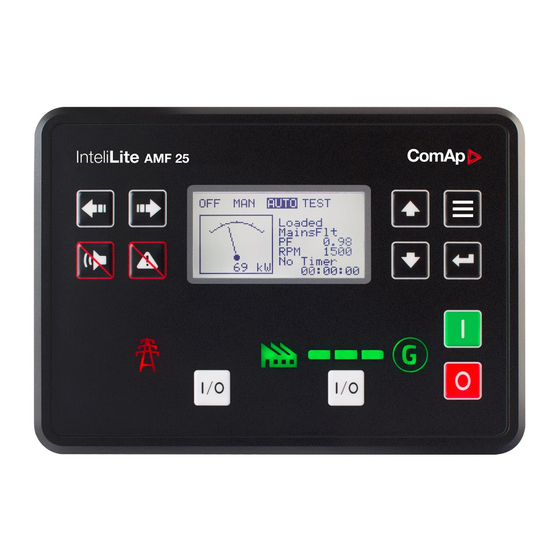
5.3 Operator Guide 5.3.1 Front panel elements 5.3.2 Display screens and pages structure 5.3.3 Browsing alarms 5.3.4 Password 5.3.5 Information screen 5.3.6 Language selection 5.3.7 Display contrast adjustment 5.3.1 Front panel elements Image 5.12 Operator interface of MRS16 Control buttons Position Picture Description LEFT button. -
Page 60: Display Screens And Pages Structure
Note: This button will not change the mode if the controller mode is forced by one of binary inputs listed in the Reference Guide – “Operating modes” chapter. HORN RESET button. Use this button to deactivate the horn output without acknowledging the alarms. - Page 61 The page Measurement consists of screens which display measured values like voltages, current, oil pressure etc., computed values like i.e. gen-set power, statistic data and the alarm list on the last screen. The page Setpoints contains all setpoints organized to groups and also a special group for entering password.
- Page 62 Note: Use Up and Down button to move between measurement pages. Note: Use Up and Down button to move between measurement pages. Note: Use Up and Down button to move between measurement pages. Note: Use Up and Down button to move between measurement pages. InteliLite Global Guide...
- Page 63 Note: Use Up and Down button to move between measurement pages. Note: Use Up and Down button to move between measurement pages. Note: Use Up and Down button to move between measurement pages. Note: Use Up and Down button to move between measurement pages. InteliLite Global Guide...
- Page 64 Note: Use Up and Down button to move between measurement pages. Note: Use Up and Down button to move between measurement pages. Note: Use Up and Down button to move between measurement pages. Note: Use Up and Down button to move between measurement pages. InteliLite Global Guide...
- Page 65 Note: Use Up and Down button to move between measurement pages. Note: Use Up and Down button to move between measurement pages. Note: Use Up and Down button to move between measurement pages. Note: Use Up and Down button to move between measurement pages. InteliLite Global Guide...
- Page 66 Note: Use Up and Down button to move between measurement pages. Note: Use Up and Down button to move between measurement pages. Note: Use Up and Down button to move between measurement pages. Note: Use Up and Down button to move between measurement pages. InteliLite Global Guide...
- Page 67 Note: Use Up and Down button to move between measurement pages. Note: Use Up and Down button to move between measurement pages. Note: Use Up and Down button to move between measurement pages. Note: From all of these pages it is possible to switch seamlessly to the setpoint group page by pressing Page button.
- Page 68 Setpoint Screens Note: From all measurement pages we can fluently go to the setpoint group page by pressing Page button. Note: Use Up and Down button to select required setpoint group. Note: Use Enter button to enter selected setpoint group. Note: Use Left and Right button to select required setpoint.
- Page 69 Note: Use Up and Down button to set required value of selected setpoint. Note: Use Enter button to confirm adjusted value of setpoint. Note: Use Page button to discard changes, to set setpoint to previous value and to return to the list of setpoints of selected group.
- Page 70 Note: Use Up and Down button to select required alarm reason. Note: Use Enter button to move to the next page of history log. Note: Use Up and Down button to select required alarm reason. Note: Use Enter button to move to the next page of history log. Note: Use Up and Down button to select required...
- Page 71 Note: Use Up and Down button to select required alarm reason. Note: Use Enter button to move to the next page of history log. Note: Use Up and Down button to select required alarm reason. Note: Use Enter button to move to the next page of history log. Note: Use Up and Down button to select required...
- Page 72 Note: Use Up and Down button to select required alarm reason. Note: Use Enter button to move to the next page of history log. Note: Use Up and Down button to select required alarm reason. Note: Use Enter button to move to the next page of history log. Note: Use Up and Down button to select required...
-
Page 73: Browsing Alarms
Note: Use Up and Down button to select required alarm reason. Note: Use Enter button to move to the next page of history log. Note: Use Up and Down button to select required alarm reason. Note: Use Enter button to move to the first page of history log. IMPORTANT: The records are numbered in reverse order, i.e. -
Page 74: Password
Active alarms are displayed as white text on black background. It means the alarm is still active, i.e. the appropriate alarm conditions are still present. Inactive alarms are displayed as black text on white background. It means the alarm is no more active, i.e. the appropriate alarm conditions are gone. - Page 75 Note: Use Up and Down button to select setpoint group Password. Note: Use Enter button to enter setpoint group Password. Note: Use Up and Down button to select Enter Password. Note: Use Enter button to enter selected setpoint. Note: Use Up and Down button to set required value of selected setpoint.
- Page 76 Note: In case that invalid password is entered, the controller shows Invalid password screen. Use Page button to go back to menu. Change password Note: From all measurement pages we can fluently go to the setpoint group page by pressing Page button. Note: Use Up and Down button to select setpoint group...
- Page 77 Note: Use Up and Down button to select required level of password. Note: Use Enter button to enter selected setpoint. Note: Use Up and Down button to set required value of password. Note: Use Left and Right button to move between digits. Note: After setting new password use Enter button to confirm adjusted password.
- Page 78 Note: Before changing the password controller has to be unlocked. In case that controller is locked, the controller shows Password required screen. In that case the password has to be entered before changing the password. Log out from controller Note: From all measurement pages we can fluently go to the setpoint group page by pressing Page button. Note: Use Up and Down button to select setpoint...
- Page 79 Note: Use Up and Down button to set required value of selected setpoint. Note: Use Left and Right button to move between digits. Note: Enter invalid password to log out from controller. Note: In case that invalid password is entered, the controller shows Invalid password screen. Use Page button to go back to menu.
-
Page 80: Information Screen
5.3.5 Information screen Note: On Main measurement screen press Enter and Page button together. Enter button has to be pressed first. Note: Use Page button to move to the next page. Note: Use Page button to move to the next page. Note: Use Up button to move back to main measurement screen. -
Page 81: Language Selection
5.3.6 Language selection Note: On Main measurement screen press Enter and Page button together. Enter button has to be pressed first. Note: Use Page button to move to the next page. Note: Use Page button to move to the next page. Note: Use Page button to move to the next page. -
Page 82: Display Contrast Adjustment
Note: Use Up and down button to select required language. Note: Use Enter button to confirm selected language. 5.3.7 Display contrast adjustment Note: On any measurement screen press Enter and Note: On any measurement screen press Enter and Down button together for lower contrast. Up button together for higher contrast. -
Page 83: General Description
5.4.1 General description Remote display software works as “remote display and control” for the Master InteliLite family controller. Gen- set can be controlled using Remote display and Master controller simultaneously and independently. All Remote display screens (Measurement screens, Setpoint screens and History Log) displays the same data as Master controller. -
Page 84: Interconnection Variants
5.4.4 Interconnection variants RS232 It is necessary to use CM-RS232-485 communication module on both Master controller and Remote display. COM 1 communication channel is used with these settings: COM 1 Mode: Direct COM 1 Communication Speed: 57600 or 115200 bps Controller Address: 1 –... -
Page 85: Connection Process
RS232 + RS485 It is possible to combine two previous ways of interconnection and connect two Remote display to one Master controller concurrently. All the parameters and settings are the same as mentioned above. 5.4.5 Connection process Remote display after power on automatically tries connect to last known Master (if such configuration exist in Remote display). -
Page 86: Function Description
Page button for more than 3 seconds. 5.4.8 Firmware compatibility Remote Display Remote Display FW is possible to upload into following controllers: InteliLite AMF25 InteliLite AMF20 InteliLite MRS16 InteliLite MRS11 InteliLite 9 Remote Display vs. Master controller Remote Display Master controller RD FW ver. -
Page 87: Functions
5.5 Functions 5.5.1 Start-stop sequence 5.5.2 Operating Modes 5.5.3 Engine start 5.5.4 Stabilization 5.5.5 Connecting to load 5.5.6 MRS operation 5.5.7 Dual Operation 5.5.8 Engine cool down and stop 5.5.9 Alarm management 5.5.10 History log 5.5.11 Breaker control 5.5.12 Exercise timers 5.5.13 Rental Timers 5.5.14 Service timers 5.5.15 Analog switches... - Page 88 Active no shutdown alarm active, other than OFF Mode selected Prestart Prestart time elapsed 572) Cranking OLENOID PAGE 597) Maximum TARTER PAGE Cranking Time (page 190) counter started Cranking RPM > Starting RPM 597) off, Starting TARTER PAGE RESTART 585) PAGE D+ input activated or oil pressure 597)
-
Page 89: Operating Modes
RPM = 0 or any other shutdown 572) off, Shutdown OLENOID PAGE condition 598) OLENOID PAGE Start request 587) Running EADY PAGE Stop RPM = 0, Oil pressure not detected, Ready Generator voltage < 10V, D+ not active If at least one of engine running Stop (Stop indication is detected when Stop... -
Page 90: Engine Start
AUTO The controller does not respond to buttons Start , Stop and GCB ON/OFF .Engine start/stop request is given by binary input Remote Start/Stop (page 536). 5.5.3 Engine start Diesel engine The setpoint Fuel Solenoid (page 189) has to be switched to the Diesel position. After the command for start is issued (pressing Start button in MAN mode, auto start condition is fulfilled in AUTO mode or controller is switched to TEST mode), outputs 585) - Page 91 Image 5.13 Flowchart of start of diesel engine InteliLite Global Guide...
- Page 92 GAS engine The setpoint Fuel Solenoid (page 189) has to be switched to the Gas position. After the command for start is issued (pressing Start button in MAN mode, auto start condition is fulfilled in AUTO mode or controller is switched to TEST mode), outputs 585) RESTART PAGE...
- Page 93 Image 5.14 Flowchart of start of gas engine InteliLite Global Guide...
-
Page 94: Stabilization
5.5.4 Stabilization When the Engine start (page 90) sequence is finished, the gen-set goes into the stabilization phase. There are two timers (setpoints) in this phase: Minimal Stabilization Time (page 200) starts to count down just after the idle period has finished. Generator voltage and frequency are not checked (respective protections are not evaluated) and the GCB cannot be closed even if the generator voltage and frequency are within limits. -
Page 95: Dual Operation
5.5.7 Dual Operation Dual operation - MRS Dual operation MRS consists 2 gen-sets. Principle of dual operation is in switching the gen-sets in supplying of load when 536) is activated on Master controller (on slave controller this LBI has EMOTE TART PAGE no function in Dual Operation). - Page 96 Dual operation adjustment Prepare two InteliLite AMF25 or two InteliLite MRS16 controllers with CM-RS232-485 modules Copy the identical configurations to both of them Use wiring with mechanical/electrical interlock between all breakers (mechanical interlock is preferred)
-
Page 97: Engine Cool Down And Stop
Change the mode of both controllers to AUTO System is now ready for dual operation function Note: Breakers feedbacks are recommended, but not required. Alarms related to dual operation: Dual Operation Fail (page 665) Dual Operation Master Fail (page 665) Dual Operation Slave Fail (page 665) Dual Operation Different FW Version (page 664) 5.5.8 Engine cool down and stop... - Page 98 Each alarm causes a record to be written into the history log. Each alarm activates the Alarm and Horn output. Each alarm can cause sending of a SMS message or an email. Image 5.15 Analog input alarm evaluation principle Alarm handling There are three different alarm categories regarding the period when the alarms are evaluated.
- Page 99 Alarm states An alarm can have following states: Active alarm: the alarm condition persists, alarm delay has elapsed. Inactive alarm: the alarm condition has disappeared, but the alarm has not been confirmed. Confirmed alarm: the alarm condition persists, but the alarm has already been confirmed. Image 5.16 Alarm List Alarm types - Level 1 The level 1 alarm indicates that a value or parameter is out of normal limits, but has still not reached critical...
- Page 100 shutdown alarm in the alarmlist. Activates the output AL C 544) as well as the standard alarm OMMON PAGE outputs 581) 552)). PAGE LARM PAGE Breaker open and cool down (BOC) The event appears in the alarmlist and is recorded into the history log. It causes immediate opening of the GCB and then the standard stop sequence with cooling follows.
- Page 101 Event Warning Shutdown Event Warning Shutdown Terminal email email email email CM-RS232-485 CM-Ethernet CM-GPRS yes* yes* yes* yes* CM-4G-GPS yes* yes* yes* yes* Note: * Only with enabled Internet Connection (page 359). Alarmlist Alarmlist is a container of active and inactive alarms. It will appear automatically on the controller display, if a new alarm occurs, or can be displayed manually from the display menu.
- Page 102 Events Protection Description specification type Value measured on analog input 2 is </> than Analog Protection 2 Analog Input 2 Sd Sd (page 245) setpoint. Value measured on analog input 3 is </> than Analog Protection 3 Analog Input 3 Wrn Wrn (page 247) setpoint.
-
Page 103: History Log
Events Protection Description specification type During starting of the engine when the RPM reach the value of Starting RPM (page 191) setpoint the starter is switched off and the Sd Underspeed speed of the engine can drop under Starting RPM (page 191) again. -
Page 104: Breaker Control
Record structure Name Abbreviation Description Row number (0 corresponds to the last record, -1 to the previous Number one, etc.) Reason Reason Reason for history record (any event or alarm related to the gen-set Time Time Time Date Date Date Engine rotations per minute Power Generator active power... - Page 105 The control outputs must be configured and wiring of the power switches must be provided in such a way, that the controller has full control over the breakers – i.e. the controller can open and close the breaker at any time.
- Page 106 IMPORTANT: It is necessary to configure breaker feedback to use this function. IMPORTANT: Also it is possible to use breakers without feedbacks. In this case there is no check of breaker real state. There are three different time delays for breaker fail detection – see following diagrams. When binary output breaker close/open is in steady state and breaker feedback is changed the breaker fail is detected immediately (no delay).
-
Page 107: Exercise Timers
Image 5.21 Breaker fail - breaker close/open opens When binary output breaker close/open closes there is 2 sec delay for breaker fail detection. Image 5.22 Breaker fail - breaker close/open closes 5.5.12 Exercise timers The exercise (general-purpose) timers in controller are intended for scheduling of any operations such as e.g. periodic tests of the gen-set, scheduled transfer of the load to the gen-set prior to an expected disconnection of the mains etc. - Page 108 Related setpoints for timer 2 are: Timer 2 Function (page 310) Timer 2 Day (page 315) Timer 2 Repetition (page 311) Timer 2 Repeated Day In Week (page 316) Timer 2 First Occur. Date (page 312) Timer 2 Repeat Day In Month (page 316) Timer 2 First Occur.
- Page 109 Image 5.23 Once mode - InteliConfig In timer mode select Once. In timer settings adjust date and time of occurrence of timer. Also adjust the duration of timer. Set-up via controller interface In controller go to the Scheduler setpoint group. Select the function of timer via Timer 1 Function (page 303) setpoint.
- Page 110 Image 5.24 Daily mode - InteliConfig In timer mode select Repeat. In repetition type select Daily. In timer settings adjust date and time of first occurrence of timer. Also adjust the duration of each occurrence of timer. Than select the x-th day of repetition (Timer 1 Refresh Period (page 307)) and behavior of timer on weekends (Timer 1 Weekends (page...
- Page 111 Image 5.25 Weekly mode - InteliConfig In timer mode select Repeat. In repetition type select Weekly. In timer settings adjust date and time of first occurrence of timer. Also adjust the duration of each occurrence of timer. Than select the x-th week of repetition (Timer 1 Refresh Period (page 307)) and days when timer should be active (Timer 1 Day (page...
- Page 112 There are two types of monthly repetition. First of them is based on repeating one day in month. Image 5.26 Monthly mode - InteliConfig In timer mode select Repeat. In repetition type select Monthly. In timer settings adjust date and time of first occurrence of timer.
- Page 113 Second type of monthly repetition is based on repeating days in week in month. Image 5.27 Monthly mode - InteliConfig In timer mode select Repeat. In repetition type select Monthly. In timer settings adjust date and time of first occurrence of timer. Also adjust the duration of each occurrence of timer. Than select the type of monthly repetition, the x-th week of repetition and days in week.
-
Page 114: Rental Timers
Short period mode Set-up via InteliConfig To set-up timer via InteliConfig go to the setpoint ribbon, setpoint group scheduler and setpoint Timer 1 Setup. Note: First of all function of timer has to be adjusted via setpoint Timer 1 Function (page 303). -
Page 115: Service Timers
How to set-up rental timer This is a short guide for settings of rental timers. Please see following few steps how to set up rental timers: Choose the type of rental timer Rental Timer 1 (page 317) (based on engine running hours) Rental Timer 2 (page 319) (based on date) Adjust the length of chosen timer... - Page 116 Analog switch Setpoints Binary output Analog Switch 6 On (page 258) AIN S 06 ( 625) AIN S 06 ( 555) WITCH PAGE WITCH PAGE Analog Switch 6 Off (page 259) Analog Switch 7 On (page 261) AIN S 07 ( 626) AIN S 07 (...
-
Page 117: Additional Running Engine Indications
Image 5.29 Principle of analog switch 5.5.16 Additional running engine indications It is helpful to have information other than speed (RPM), whether the engine is rotating or not, especially if RPM is measured from the generator frequency instead of magnetic pickup. The generator frequency measurement can be unreliable at very low speeds and/or may have a delayed reaction to sudden and big changes (i.e. -
Page 118: Gen-Set Operation States
5.5.18 Gen-set operation states Engine state machine Autotest during controller power on. Note: Sometimes controller stays in Init mode after FW upgrade. It means that there are Init new parameters which should be checked by user. It is possible to disable this control via InteliConfig. - Page 119 Still engine conditions Engine speed (RPM) < Starting RPM (page 191) Oil pressure < Starting Oil Pressure (page 192) Binary input 534) is in logical 1 or RESSURE PAGE Generator voltage < 50 V (any phase) Note: When the engine was running before and all above conditions are fulfilled, additional 2 s delay is necessary to confirm “still engine”.
-
Page 120: Sensor Curves
Image 5.31 Engine stops after first Stop Time (page 203) Electric state machine IslOper Island operation BrksOff GCB opened 5.5.19 Sensor curves Background of the sensor calibration To correct measuring error of each analog input (pressure, temperature, level, etc.) calibrating constants should be set. - Page 121 General line 4 1000 General line 5 1000 General line 6 1000 General line 7 1000 General line 8 1000 General line 9 1000 General line 10 1000 General line 11 1000 General line 12 1000 General line 13 1000 Note: Curves can be modified via InteliConfig.
-
Page 122: Plc
5.5.20 PLC PLC Editor is powerful tool which helps you to create your own PLC scheme. It has graphical interface to have user interface easy to use. Image 5.32 PLC Editor main page List of available PLC blocks PLC block Number of blocks OR/AND XOR/RS... - Page 123 Working with the editor If the currently opened archive does not contain any PLC program, then an empty drawing is created automatically when you select the PLC Editor. The procedure of creation of a PLC drawing (program) contains following essential steps: Adjust the sheet to your needs.
- Page 124 Connect the block inputs and outputs by drawing wires in the sheet. See Define inputs and outputs (page 124) for more information. It is also possible to connected inputs and outputs via properties of selected PLC block. Image 5.34 Adding PLC blocks Note: To delete PLC block just click on it and press delete button.
- Page 125 Inputs Sheet inputs are located at the left side of a sheet. Follow the procedure below to add or edit an input. Double-click on a free input position or existing input to add new input or edit the existing one. Select the source for the input.
- Page 126 Image 5.36 PLC inputs Outputs Sheet outputs are located at the right side of a sheet. Follow the procedure below to add or edit an input. Doubleclick on a free output position to add new sheet output. Doubleclick on an already created output to configure the output onto a controller output terminal or a logical binary input (first of all some PLC block output has to be connected to this output to enable configuration of output).
- Page 127 Image 5.37 PLC outputs IMPORTANT: It is necessary to click on Connect button after selecting the output. Otherwise PLC output is not connected to output. Creating wires Wires can be create between PLC inputs and PLC blocks and between PLC blocks and PLC outputs. IMPORTANT: Keep the order of starting and finishing connection points.
- Page 128 Note: It is possible to make connection only between the outputs and inputs with the same type of value (binary or analog). Binary values are marker by black pointer, analog values are marked with green pointer. Note: To delete wire just click on it and press delete button. Also delete selection function can by used. PLC logic execution rules The PLC program is executed every 100 ms.
-
Page 129: Geo-Fencing
Other functions Consistency check Use this function to check if all inputs and outputs of PLC block are connected. Delete whole content of sheet Use this function to delete the whole content of sheet (including blocks, wires, inputs, outputs, etc...). Hints Use this function to enable or disable quick hints for blocks (controller help is not affected by this function). - Page 130 inactive lamps are represented by "dotted" icons. For no active lamp the screen shows all dotted icons. Please see examples below: Image 5.39 Example of active Tier 4 Final screen Image 5.40 Example of inactive Tier 4 Final screen Universal lamps (icons) Universal lamp icons are shown on the After-Treatment screen.
- Page 131 Lamp name Active icon Inactive icon Notes Note: This value can light Amber warning lamp or blink on both frequencies. Note: This value can light Red stop lamp or blink on both frequencies. Engine wait to start lamp Note: DPF = Diesel Particulate Filter;...
-
Page 132: Alternate Configuration
DPFAshLoad (page 454) DPFSootLoad (page 454) DEF Level (page 454) Control of After-Treatment regeneration function User can force or inhibit regeneration process by activating appropriate binary inputs of the controller. Please see the list of binary inputs below: 528) ORCE EGENERATION PAGE 535) -
Page 133: Ecu Frequency Selection
5.5.24 ECU Frequency selection Setpoint ECU Freq Select is no longer in use. However ECU Frequency Select (page 457) value was kept and the value can be calculated from Nominal Frequency (page 180) setpoint. Sequence for frequency change is executed automatically (engine must be in still condition and ECU is powered on – ECU Power Relay is not configured) in following steps: 1. - Page 134 IMPORTANT: There is a backup e-mail address defined in the controller to which and only which ComAp will send the “password reset action code”. Please be sure, that you have adjusted this e- mail address correctly. Use InteliConfig to adjust the backup e-mail address...
- Page 135 Reset password procedure 1. Connect InteliConfig. You may connect remotely if you know Access Code. 2. Get the password reset request code and send it via e-mail to support@comap-control.com InteliLite Global Guide...
- Page 136 3. Once you receive the reply from ComAp, copy the code from the e-mail (all characters inside the box as indicated below) InteliLite Global Guide...
- Page 137 4. Paste the code into the password reset window Encryption of the communication New technology “CCS v.1” is used for an authentication and an encryption of the ComAp protocol via Internet/ethernet/AirGate. This technology is based on strong and proven cryptographic algorithms and has passed successfully penetration tests and cybersecurity audit.
-
Page 138: Communication
6 Communication 6.1 PC 6.2 Connection to 3rd party systems 6 back to Table of contents 6.1 PC 6.1.1 Direct communication 6.1.2 Remote communication 6.1.1 Direct communication A RS232, USB, RS485 or ethernet interface can be used for direct cable connection to a PC. Connection via RS232 A plug-in communication module CM-RS232-485 is necessary for communication via RS232 connection. - Page 139 To connect your PC tool to the controller use the INTERNET connection type and just put the CM-Ethernet IP address into the gen-set address box in the PC tool. If you do not use the default ComAp TCP Port (page 384) 23, then you also have to specify the port number using a colon.
-
Page 140: Remote Communication
6 back to Communication 6.1.2 Remote communication A PC can be connected to the controller also remotely via CM-GPRS or CM-Ethernet plug-in module. IMPORTANT: Factory default password and access code are "0". It is highly recommended to change these parameters. Ethernet LAN connection Direct IP LAN connection is intended to be used if the CM-Ethernet module is reachable from the client computer by specifying the IP address at which the module can be contacted. - Page 141 IP address of the network gateway to the local IP address of CM- Ethernet at the port specified for ComAp protocol. Different port numbers can be used to create multiple port forwarding rules in the same local network.
- Page 142 Event SMS The InteliLite controller equipped with the CM-GPRS or CM-4G-GPS communication module is able to send Event SMS according to the setting of setpoint: Event Message (page 374) Note: Firstly setpoint Telephone Number 1 (page 368) has to be adjusted. The following events can be received by mobile phone: Engine Start/Stop Manual Start/Stop...
- Page 143 start Start the engine in MAN mode. stop Stop the engine in MAN mode. fault reset Acknowledging alarms and deactivating the horn output. gcb close Closing GCB in MAN and TEST mode. gcb open Opening GCB in MAN and TEST mode. Switching to OFF mode.
- Page 144 Message structure: Controller ----------------------------------------------- Name: XXX Serial number: XXX SW branch: XXX SW version: XXX Application: XXX Appl. version: XXX Date: dd/mm/yyyy Time: hh:mm:ss Alarm list ----------------------------------------------- Alarm 1 Alarm 2 Alarm 3 Events ----------------------------------------------- hh:mm:ss Event 1 hh:mm:ss Event 2 hh:mm:ss Event 3 Alarm Email The InteliLite controller equipped with the CM-Ethernet communication module is able to send Alarm Emails...
- Page 145 Message structure: Controller ----------------------------------------------- Name: XXX Serial number: XXX SW branch: XXX SW version: XXX Application: XXX Appl. version: XXX Date: dd/mm/yyyy Time: hh:mm:ss Alarm list ----------------------------------------------- Alarm 1 Alarm 2 Alarm 3 History events ----------------------------------------------- 0 dd/mm/yyyy hh:mm:ss.0 Event 1 -1 dd/mm/yyyy hh:mm:ss.0 Event 2 -2 dd/mm/yyyy hh:mm:ss.0 Event 3 Note: Asterisk means that alarm is unconfirmed and exclamation mark means that alarm is active.
- Page 146 Web Server IMPORTANT: The web interface is based on HTTP protocol and is intended to be used only in private networks. It is not recommended to expose the web interface to the public Internet. The Web Server is designed for basic monitoring and adjustment of the controller using a web browser. Just put the controller IP address into the browser to display the main controller web page like http://192.168.1.254.
- Page 147 Scada Click to the SCADA link in the toolbar to display the scada page. The scada page is also the main page which is displayed by default if you just put the CM-Ethernet address into the browser (after entering the right access code).
- Page 148 Measurement Click to the MEASUREMENT link in the toolbar to display the measurement page. Then click to the required group name in the left box to display values of the group in the right box. Note: The measurement page is automatically refreshed every 60 seconds (this time cannot be changed). Image 6.9 Web Server - measurement screen InteliLite Global Guide...
- Page 149 Setpoints Click to the SETPOINTS link in the toolbar to display the setpoints page. Click to the required group name in the left box to display setpoints of the group in the right box. Click to the required setpoint name or value to change the value. If the respective setpoint is protected by password, which is indicated by a lock icon by the setpoint name, you have to click on the "Controller password"...
- Page 150 History Click to the HISTORY link in the toolbar to display the history page. Use the control buttons to move within the history file. Note: The history page is automatically refreshed every 60 seconds. If a new record appears in the controller, the web page will not show it immediately as e.g.
-
Page 151: Connection To 3Rd Party Systems
Web Server Adjustment Click to the "Web Server settings" icon in the toolbar to display the settings page. Select the controller language the web pages will appear in. Select the rate of automatic refresh of the scada page. Image 6.12 Web Server - Adjustment screen 6 back to Communication 6.2 Connection to 3rd party systems 6.2.1 SNMP... - Page 152 (page 382) in the same group can be used to customize the „community strings“ for the read and write operations which have function like „passwords“. All requests sent from the SNMP Manager have to contain community string which match with the community string adjusted in the controller otherwise the controller refuses the operation.
-
Page 153: Modbus-Rtu, Modbus/Tcp
SNMP notifications Except the request-response communication model, in which the communication is controlled by the Manager, there are also messages that the Agent sends without any requests. These messages are called „Notifications“ and inform the Manager about significant events occurred in the Agent. The controller can send notifications to two different SNMP Managers (two different IP addresses). - Page 154 MODBUS MODICON object Meaning Access MODBUS function address type 0000 .. 0999 Binary objects Read only Discrete Inputs Read: 01, 02 1000 .. 2999 Values Read only Input Registers Read: 03, 04 Read: 03, 04 3000 .. 3999 Setpoints Read/Write Holding Registers Write: 06, 16 Input Registers...
- Page 155 Number of Data type Meaning Data maping registers LSB = ASCII value of the character MSB = 0 StrList Index into a list of strings LSB = index into the list MSB1 = ASCII value of the 1. character LSB1 = ASCII value of the 2. character Zero-terminated string of ShortStr MSB2 = ASCII value of the 3.
- Page 156 01 – Ilegal function is returned if an incompatible type of operation is applied for a specific object, e.g. if function 03 is applied to a binary object. 02 – illegal address is returned if the client tries to perform an operation with a object address that is not related to any existing object or that is located inside an object which is composed by multiple addresses (registers).
- Page 157 Register Number of Access Data type Meaning addresses registers 4539 - 4565 read Alarm 13. record in alarm list 4566 - 4592 read Alarm 14. record in alarm list 4593 - 4619 read Alarm 15. record in alarm list 4620 - 4646 read Alarm 16.
- Page 158 MODBUS examples Modbus RTU examples Reading of Battery voltage Export table of values from InteliConfig Table: Values Allowed MODBUS functions: 03, 04 Register(s) Com.Obj. Name Dimension Type Group Controller 01053 8213 BatteryVoltage Integer Request: (Numbers in Hex) Register address Controller address Modbus function Number of registers 041D...
- Page 159 Reading all binary inputs as modbus register Table: Values Allowed MODBUS functions: 03, 04 Register(s) Com.Obj. Name Dimension Type Group Binary 01068 8235 Binary#2 Controller I/O Inputs Request: (Numbers in Hex) Register address Controller address Modbus function Number of registers 042C = 1068 Response: (Numbers in Hex)
- Page 160 Reading binary inputs as coil status. Table: Binaries Allowed MODBUS functions: 01, 02 Addresses Source C.O.# Name of Value Bit Name Modbus Addr. = Value Bit # Group State # Name of State Activated by protection(s): Prot. Addr. = State 00000 Value 8235...
- Page 161 Starting the engine Before starting engine you may need to write password. Depends on your settings in controller. Table Reserved registers (page 156) Register addresses Number of registers Access Data type Meaning Writing:command argument 4207 - 4208 read/write Unsigned32 Reading: command return value 4209 write Unsigned16...
- Page 162 Password This password is the same as in InteliConfig or directly in controller. Table Reserved registers (page 156) Register addresses Number of registers Access Data type Meaning 4211 write Unsigned16 Password Note: Default password is "0". In this example the password is "1234". Request: (Numbers in Hex) Register address Password...
- Page 163 Nominal Power – writing Table: Setpoints Allowed MODBUS functions: 03, 04, 06, 16 Register(s) Com.Obj. Name Dimension Type Group Nominal Basic 03008 8276 Unsigned 5000 Power Settings Request: (Numbers in Hex) Register address Data Controller address Modbus function 0BC0 = 3008 0064 = 100 Response: (Numbers in Hex)
- Page 164 Modbus TCP examples Reading of Battery voltage Export table of values from InteliConfig Table: Values Allowed MODBUS functions: 03, 04 Register(s) Com.Obj. Name Dimension Type Group Controller 01053 8213 BatteryVoltage Integer Request: (Numbers in Hex) transaction protocol Length of Register address Controller Modbus Number of...
-
Page 165: Technical Data
7 Technical data Power supply Communications 8-36 VDC non-isolated Power supply range USB port 394 mA / 8 VDC CAN bus, 250 kbps, max 200 CAN 1 m, 120 Ω termination option, 255 mA / 12 VDC Power consumption non- isolated 140 mA / 24 VDC 97 mA / 36 VDC Current measurement... - Page 166 Magnetic pickup 4 Vpk-pk to 50 Vpk-pk in range 4 Hz to 1 kHz 6 Vpk-pk to 50 Vpk-pk in Voltage input range range 1 kHz to 5 kHz 10 Vpk-pk to 50 Vpk-pk in range 5 kHz to 10 kHz Frequency input range 4 Hz to 10 kHz Frequency...
-
Page 167: Appendix
8 Appendix 8.1 Controller objects 8.2 Alarms 8.3 Modules 6 back to Table of contents InteliLite Global Guide... -
Page 168: Controller Objects
8.1 Controller objects 8.1.1 Setpoints 8.1.2 Values 8.1.3 Logical binary inputs 8.1.4 Logical binary outputs 8.1.5 Logical analog inputs 8.1.6 PLC InteliLite Global Guide... -
Page 169: Setpoints
8.1.1 Setpoints What setpoints are: Setpoints are analog, binary or special data objects which are used for adjusting the controller to the specific environment. Setpoints are organized into groups according to their meaning. Setpoints can be adjusted from the controller front panel, PC, MODBUS, etc. All setpoints can be protected by a password against unauthorized changes. - Page 170 List of setpoints Idle RPM ECU Coolant Temperature Basic settings Choke Function Gen-Set Name ECU Coolant Temperature Choke Time Nominal Power Split Choke Start Temp Phase ECU Coolant Temperature Choke Increment Nominal Power Delay Choke Voltage Nominal Current Temperature Switch On Choke Lead CT Ratio Temperature Switch Off...
- Page 171 Ventilation Pulse Time Protection Analog Protection 5 Delay 254 ECU Speed Adjustment Generator <> Voltage Analog Switch 5 On Protection Analog Switch 5 Off Generator settings Voltage Unbalance Analog Protection 6 Wrn 256 Protection Overload BOC Analog Protection 6 Sd Generator Frequency Overload Wrn Analog Protection 6 Delay 257...
- Page 172 Analog Switch 12 Off Analog Switch 19 On Timer 2 Day Analog Protection 13 Wrn 277 Analog Switch 19 Off Timer 2 Repeat Day Analog Protection 13 Sd 278 Analog Protection 20 Wrn 298 Timer 2 Repeated Day In Week Analog Protection 13 Analog Protection 20 Sd 299 Delay...
- Page 173 SMTP User Name AirGate Connection Nominal RPM 2 SMTP User Password AirGate Address Nominal Voltage Ph-N 2 SMTP Server Address ComAp TCP Port Nominal Voltage Ph-Ph 2 336 SMTP Sender Address Email Address 1 Nominal Power 2 Time Zone Email Address 2...
- Page 174 ComAp TCP Port PLC Setpoint 28 Web Interface PLC Setpoint 29 PLC Setpoint 30 Extension Modules PLC Setpoint 31 Earth Fault Current PLC Setpoint 32 Protection PLC Setpoint 33 Earth Fault Delay PLC Setpoint 34 Earth Fault CT Input PLC Setpoint 35...
- Page 175 Group: Basic settings Subgroup: Name Gen-Set Name Setpoint group Basic settings Related FW 1.9.0 Range [units] 0 .. 15 characters [-] Default value InteliLite Alternative config Step Comm object 8637 Related applications AMF, MRS Config level Standard Setpoint visibility Always Description User defined name, used for the controller identification at remote phone or mobile connection.
- Page 176 Nominal Power Setpoint group Basic settings Related FW 1.9.0 Range [units] 1 .. 5 000 [kW] Default value 200 kW Alternative config Step 1 kW Comm object 8276 Related applications AMF, MRS Config level Standard Setpoint visibility Always Description Nominal power of the gen-set. Generator Overload BOC (page 227) protection is based on this setpoint.
- Page 177 CT Ratio Setpoint group Basic settings Related FW 1.9.0 Range [units] 1 .. 5 000 [A/5A] Default value 2 000 A/5A Alternative config Step 1 A/5A Comm object 8274 Related applications AMF, MRS Config level Standard Setpoint visibility Always Description Gen-set current transformers ratio.
- Page 178 2x CT (Current Transformer) 3Ph4Wire Grounded Star (Grounded Wye) connection – 3PY Three phase voltage measurement L1,L2,L3 with 120° phase shift 3x CT (Current Transformer) 3Ph3Wire Ungrounded Delta connection Open Delta Ungrounded Wye Corner-Grounded Delta Split Phase Delta Three phase voltage measurement L1,L2,L3 with 120° phase shift No neutral is available 3x CT (Current Transformer) High Leg D High Leg Delta connection...
- Page 179 L3 >=100V Mono Phase L1 >=100V L2 <= 20V L3 <= 20V Voltage Autodetect shutdown Note: To lock this setpoint against editing you also have to lock setpoint Connection Type 1 (page 329), Connection type 2 (page 333) Connection type 3 (page 337).
- Page 180 PT Ratio Setpoint group Basic settings Related FW 1.9.0 Range [units] 0,1 .. 500,0 [V/V] Default value 1,0 V/V Alternative config Step 0,1 V/V Comm object 9579 Related applications AMF, MRS Config level Advanced Setpoint visibility Always Description Generator voltage potential transformers ratio. If no PTs are used, adjust the setpoint to 1. 6 back to List of setpoints Vm PT Ratio Setpoint group...
- Page 181 Gear Teeth Setpoint group Basic settings Related FW 1.9.0 Range [units] FGen->RPM / 1 .. 500 [-] Default value Alternative config Step Comm object 8252 Related applications AMF, MRS Config level Advanced Setpoint visibility Always Description Number of teeth on the engine flywheel where the pick-up is installed. Set to zero if no pick-up is used and the Engine speed will be counted from the generator frequency.
- Page 182 Subgroup: Controller settings Controller mode Setpoint group Basic settings Related FW 1.9.0 Range [units] OFF / MAN / AUTO[-] Default value Alternative config Step Comm object 8315 Related applications AMF, MRS Config level Advanced Setpoint visibility Always Description This setpoint can be used for changing the Controller mode remotely, e.g. via MODBUS. Use the mode selector on the main screen for changing the mode from the front panel.
- Page 183 Operation Mode Setpoint group Basic settings Related FW 1.9.0 Range [units] AMF / MRS [-] Default value Alternative config Step Comm object 12157 Related applications Config level Advanced Setpoint visibility Always Description Based on this setpoint is defined basic controller function. Normal AMF operation When MRS mode is selected the controller will not perform AMF functions anymore.
- Page 184 Reset To Manual Setpoint group Basic settings Related FW 1.9.0 Range [units] Disabled / Enabled [-] Default value Disabled Alternative config Step Comm object 9983 Related applications AMF, MRS Config level Advanced Setpoint visibility Always Description If this function is enabled, the controller will switch automatically to MAN mode when there is a red alarm in the alarm list and fault reset button is pressed.
- Page 185 Horn Timeout Setpoint group Basic settings Related FW 1.9.0 Range [units] Disabled / 1 .. 599 [s] Default value 10 s Alternative config Step Comm object 8264 Related applications AMF, MRS Config level Advanced Setpoint visibility Always Description Setting of horn behavior. Disabled Disabling the Horn sounding function Timeout for...
- Page 186 RunHoursSource Setpoint group Basic settings Related FW 1.9.0 Range [units] AUTO/ECU/INTERNAL [-] Default value AUTO Alternative config Step Comm object 13345 Related applications AMF, MRS Config level Advanced Setpoint visibility Always Description This setpoint selects source of running hours AUTO If there is some ECU which send valid running hours, then this value is used.
- Page 187 Screen Filter Setpoint group Basic settings Related FW 1.9.0 Range [units] Enable/Disabled [-] Default value Disabled Alternative config Step Comm object 15889 Related applications AMF, MRS Config level Advanced Setpoint visibility Always Description This setpoint enables/disables filter values on CU screen and PC tools. List of values which are filtered when filter is ON.
- Page 188 Subgroup: HMI Settings Main Screen Line 1 Setpoint group Basic settings Related FW 1.9.0 Range [units] RPM/PF/Run Hours/ATT/AIN1 [-] Default value Alternative config Step Comm object 13346 Related applications AMF, MRS Config level Advanced Setpoint visibility Always Description This setpoint adjusts line 1 on Mains screen. 6 back to List of setpoints Main Screen Line 2 Setpoint group...
- Page 189 Fuel Solenoid Setpoint group Engine settings Related FW 1.9.0 Range [units] Diesel / Gas [-] Default value Diesel Alternative config Step Comm object 9100 Related applications AMF, MRS Config level Advanced Setpoint visibility Always Description Determines behavior of the Binary output 572) OLENOID PAGE...
- Page 190 Maximum Cranking Time Setpoint group Engine settings Related FW 1.9.0 Range [units] 1 .. 255 [s] Default value Alternative config Step Comm object 8256 Related applications AMF, MRS Config level Advanced Setpoint visibility Always Description Maximum time limit of cranking time. IMPORTANT: There is a protection against broken pinion on starter.
- Page 191 Prestart Time Setpoint group Engine settings Related FW 1.9.0 Range [units] 0 .. 600 [s] Default value Alternative config Step Comm object 8394 Related applications AMF, MRS Config level Standard Setpoint visibility Always Description Time of closing of the 585) output prior to the engine start.
- Page 192 Starting Oil Pressure Setpoint group Engine settings Related FW 1.9.0 Range [units] Disabled / 0,1 .. 10,0 [bar] Default value 4,5 bar Alternative config Step 0,1 bar Comm object 9681 Related applications AMF, MRS Config level Standard Setpoint visibility Always Description Oil pressure limit for starting.
- Page 193 Subgroup: Choke Choke Function Setpoint group Engine settings Related FW 1.9.0 Range [units] Disabled /Fixed Time / Temp Based [-] Default value Disabled Alternative config Step Comm object 15717 Related applications MRS. AMF Config level Advanced Setpoint visibility Only when LBO 567) is configured.
- Page 194 Choke Start Temp Setpoint group Engine settings Related FW 1.9.0 Range [units] -20,0 .. 80,0 [°C] Default value 0,0 °C Alternative config Step 0,1 °C Comm object 15716 Related applications MRS. AMF Config level Advanced Only when LBO 567) is configured and setpoint Choke Function (page HOKE PAGE...
- Page 195 Choke Increment Setpoint group Engine settings Related FW 1.9.0 Range [units] 0,00 .. 20,00 [s/°C] Default value 0,00 s/°C Alternative config Step 0,01 s/°C Comm object 15715 Related applications MRS. AMF Config level Advanced Only when LBO 567) is configured and setpoint Choke Function HOKE PAGE...
- Page 196 Choke Voltage Setpoint group Engine settings Related FW 1.9.0 Range [units] Disabled / 1–100 [%] Default value Disabled Alternative config Step Comm object 15718 Related applications MRS. AMF Config level Advanced Setpoint visibility Only when LBO 567) is configured. HOKE PAGE Description This setpoint adjust threshold level for deactivation of...
- Page 197 Choke Lead Setpoint group Engine settings Related FW 1.9.0 Range [units] 0 .. Prestart Time [s] Default value Alternative config Step Comm object 15774 Related applications MRS. AMF Config level Advanced Setpoint visibility Only when LBO 567) is configured. HOKE PAGE Description This setpoint adjust the lead of logical binary output C...
- Page 198 Subgroup: Starting Timers Fuel Solenoid Lead Setpoint group Engine settings Related FW 1.9.0 Range [units] 0,0 .. 25,0 [s] Default value 0,5 s Alternative config Step 0,1 s Comm object 10525 Related applications AMF, MRS Config level Advanced Setpoint visibility Always Description Delay between...
- Page 199 nominal speed. Image 8.3 Idle Time 1 Image 8.4 Idle Time 2 6 back to List of setpoints InteliLite Global Guide...
- Page 200 Minimal Stabilization Time Setpoint group Engine settings Related FW 1.9.0 Range [units] 1 .. Maximal Stabilization Time (page 201) Default value Alternative config Step Comm object 8259 Related applications AMF, MRS Config level Standard Setpoint visibility Always Description When the gen-set has been started and the idle timer has elapsed, the controller will wait for a period adjusted by this setpoint before closing GCB, even if the generator voltage and frequency are already in limits.
- Page 201 Maximal Stabilization Time Setpoint group Engine settings Related FW 1.9.0 Range [units] Minimal Stabilization Time (page 200) .. 300 [s] Default value 10 s Alternative config Step Comm object 8313 Related applications AMF, MRS Config level Advanced Setpoint visibility Always Description When the gen-set has been started and the idle timer has elapsed, the generator voltage and frequency must get within limits within this period of time, otherwise an appropriate shutdown alarm (generator voltage and/or...
- Page 202 Sd Ventilation Time Setpoint group Engine settings Related FW 1.9.0 Range [units] 0 .. 60 [s] Default value Alternative config Step Comm object 9695 Related applications AMF, MRS Config level Advanced Setpoint visibility Always Description In case Fuel Solenoid (page 189) is set to GAS, the Sd Ventilation Time adjusts the time of the starter to be switched on for engine pre-ventilation in the case of a first start attempt after shutdown or controller switch-on.
- Page 203 Subgroup: Stopping Timers Cooling Time Setpoint group Engine settings Related FW 1.9.0 Range [units] 0 .. 3 600 [s] Default value 30 s Alternative config Step Comm object 8258 Related applications AMF, MRS Config level Standard Setpoint visibility Always Description Runtime of the unloaded gen-set to cool the engine before stop.
- Page 204 Image 8.8 Stop Time 2 6 back to List of setpoints After Cooling Time Setpoint group Engine settings Related FW 1.9.0 Range [units] 0 .. 3 600 [s] Default value 180 s Alternative config Step Comm object 8662 Related applications AMF, MRS Config level Standard...
- Page 205 Enabled The D+ terminal is used for both functions – “running engine” detection and charge fail detection. ChargeFail The D+ terminal is used for charge fail detection only Disabled The D+ terminal is not used. Image 8.9 D+ Function 1 Image 8.10 D+ Function 2 6 back to List of setpoints InteliLite Global Guide...
- Page 206 D+ Treshold Setpoint group Engine settings Related FW 1.9.0 Range [units] 0..100 [%] Default value 80 % Alternative config Step Comm object 14959 Related applications MRS. AMF Config level Advanced Setpoint visibility Only if setpoint D+ Function (page 204) is not set to Disabled value. Description This setpoint adjusts threshold level for D+ function.
- Page 207 Subgroup: Engine Protections Overspeed Sd Setpoint group Engine settings Related FW 1.9.0 Range [units] Underspeed Sd (page 207) .. 200 [%] Default value 115% Alternative config Step 1 % of Nominal RPM (page 181) Comm object 8263 Related applications AMF, MRS Config level Standard Setpoint visibility Always...
- Page 208 Overspeed Overshot Period Setpoint group Engine settings Related FW 1.9.0 Range [units] 0 .. 255 [s] Default value Alternative config Step Comm object 14108 Related applications AMF, MRS Config level Standard Setpoint visibility Conditioned by the setpoint Overspeed Overshot (page 207) Description Time for which is Overspeed Overshot (page 207)
- Page 209 Oil Pressure Delay Setpoint group Engine settings Related FW 1.9.0 Range [units] 0 .. 900 [s] Default value Alternative config Step Comm object 14341 Related applications AMF, MRS Config level Standard Visible only if the logical analog input 634) is configured or RESSURE PAGE Setpoint visibility...
- Page 210 ECU Oil Pressure Delay Setpoint group Engine settings Related FW 1.9.0 Range [units] 0 .. 900 [s] Default value Alternative config Step Comm object 14427 Related applications AMF, MRS Config level Standard Setpoint visibility Visible only if ECU is configured Description Delay for Oil pressure which is send from ECU.
- Page 211 Coolant Temperature Delay Setpoint group Engine settings Related FW 1.9.0 Range [units] 0 .. 900 [s] Default value Alternative config Step Comm object 14342 Related applications AMF, MRS Config level Standard Visible only if the logical analog input 631) is configured or OOLANT PAGE Setpoint visibility...
- Page 212 ECU Coolant Temperature Delay Setpoint group Engine settings Related FW 1.9.0 Range [units] 0 .. 900 [s] Default value Alternative config Step Comm object 14430 Related applications AMF, MRS Config level Standard Setpoint visibility Visible only if ECU is configured Description Delay for Coolant temperature which is send from ECU.
- Page 213 Temperature Switch Off Setpoint group Engine settings Related FW 1.9.0 Range [units] the range is define by sensor curve (analog or ECU) the value is defined by Default value sensor curve (analog or Alternative config ECU) Step the step is defined by sensor curve (analog or ECU) Comm object 8689 Related applications...
- Page 214 Coolant Temperature Low Delay Setpoint group Engine settings Related FW 1.9.0 Range [units] 0 .. 900 [s] Default value Alternative config Step Comm object 10270 Related applications AMF, MRS Config level Advanced Setpoint visibility Visible only if the logical analog input 631) is configured OOLANT...
- Page 215 Fuel Level Delay Setpoint group Engine settings Related FW 1.9.0 Range [units] 0 .. 900 [s] Default value 10 s Alternative config Step Comm object 14343 Related applications AMF, MRS Config level Standard Visible only if the logical analog input 632) is configured or logical EVEL...
- Page 216 ECU Fuel Level Delay Setpoint group Engine settings Related FW 1.9.0 Range [units] 0 .. 900 [s] Default value 10 s Alternative config Step Comm object 14433 Related applications AMF, MRS Config level Standard Setpoint visibility Visible only if ECU is configuredd Description Delay for Fuel level which is send from ECU.
- Page 217 Maximal Fuel Drop Delay Setpoint group Engine settings Related FW 1.9.0 Range [units] 0 .. 600 [s] Default value Alternative config Step Comm object 14683 Related applications AMF, MRS Config level Advanced Setpoint visibility Always Description When the value of fuel drop per hour is higher than Maximal Fuel Drop (page 216) this delay stars count down.
- Page 218 Fuel Pump Off Setpoint group Engine settings Related FW 1.9.0 Range [units] Fuel Pump On (page 217) .. 100 [%] Default value 90 % Alternative config Step Comm object 10101 Related applications AMF, MRS Config level Advanced Visible only if the logical binary output 572) is configured and PAGE...
- Page 219 Transfer Wrn Delay Setpoint group Engine settings Related FW 1.9.0 Range [units] Disabled / 1 .. 60 [s] Default value 30 s Alternative config Step Comm object 10685 Related applications AMF, MRS Config level Advanced Setpoint visibility Visible only if the logical binary output 572) is configured PAGE...
- Page 220 Maintenance Timer 2 Setpoint group Engine settings Related FW 1.9.0 Range [units] -10 000 ... 9 999 [h] / Disabled Default value 1 000 h Alternative config Step Comm object 11617 Related applications AMF, MRS Config level Standard Setpoint visibility Always Description Maintenance timer 2 counts down when engine is running.
- Page 221 Battery Overvoltage Setpoint group Engine settings Related FW 1.9.0 Range [units] Battery Undervoltage (page 220) .. 40,0 [V] Default value 36,0 V Alternative config Step 0,1 V Comm object 9587 Related applications AMF, MRS Config level Standard Setpoint visibility Always Description Warning threshold for high battery voltage.
- Page 222 Low Battery Charging Cycle Setpoint group Engine settings Related FW 1.9.0 Range [units] Disabled / 1–240 [min] Default value Disabled Alternative config Step 1 min Comm object 15766 Related applications Config level Advanced Setpoint visibility Always Description This setpoint enables battery charging and defines the time gen-set is running for to recharge battery. If battery charging is enabled and battery undervoltage is detected for more than 5 minutes, gen-set is started and will run for time defined in setpoint Low Battery Charging Cycle.
- Page 223 Conversion Coefficient Pulse 2 Setpoint group Engine settings Related FW 1.9.0 Range [units] 0 ... 1 000 [-] Default value Alternative config Step Comm object 10995 Related applications AMF, MRS Config level Advanced Setpoint visibility Only if LBI 535) is configured ULSE OUNTER PAGE...
- Page 224 Image 8.16 Power Switch Level On > Level Off 6 back to List of setpoints Power Switch Off Setpoint group Engine settings Related FW 1.9.0 Range [units] 0 .. 32 000 [kW] Default value 50 kW Alternative config Step 1 kW Comm object 11659 Related applications...
- Page 225 Image 8.17 Power Switch Level On < Level Off Image 8.18 Power Switch Level On > Level Off 6 back to List of setpoints InteliLite Global Guide...
- Page 226 Subgroup: Ventilation Ventilation Pulse Time Setpoint group Engine settings Related FW 1.9.0 Range [units] 0–3600 [s] Default value 30 s Alternative config Step Comm object 15767 Related applications MRS. AMF Config level Advanced Only when logical binary output 601) ENTILATION ULSE PAGE ENTILATION...
- Page 227 Group: Generator settings Subgroup: Overload Protection Overload BOC Setpoint group Generator settings Related FW 1.9.0 Range [units] Overload Wrn (page 227) .. 200 [%] Default value 120 % Alternative config Step 1 % of Nominal Power (page 176) Comm object 8280 Related applications AMF, MRS...
- Page 228 Subgroup: Current Protection Short Circuit BOC Setpoint group Generator settings Related FW 1.9.0 Range [units] 100 .. 500 [%] Default value 250 % Alternative config Step 1 % of Nominal Current (page 176) Comm object 8282 Related applications AMF, MRS Config level Standard Setpoint visibility Always...
- Page 229 IDMT Overcurrent Delay Setpoint group Generator settings Related FW 1.9.0 Range [units] 1,0 .. 600,0 [s] Default value 4,0 s Alternative config Step 0,1 s Comm object 8283 Related applications AMF, MRS Config level Standard Setpoint visibility Always Description IDMT curve shape selection. IDMT Overcurrent Delay is a reaction time of IDMT protection for 200% overcurrent I =2*Nominal Current (page 176) IDMT is “very inverse”...
- Page 230 Current Unbalance BOC Setpoint group Generator settings Related FW 1.9.0 Range [units] 1 .. 200 [%] of Nominal Current (page 176) Default value 50 % Alternative config Step 1 % of Nominal Current (page 176) Comm object 8284 Related applications AMF, MRS Config level Advanced...
- Page 231 Generator Overvoltage Wrn Setpoint group Generator settings Related FW 1.9.0 Generator Undervoltage Wrn (page 232) Generator Overvoltage Sd (page 230) Range [units] Default value 110 % Alternative config Step 1 % of Nominal Voltage Ph-N (page 179) Nominal Voltage Ph-Ph (page 179) Comm object 9686 Related applications...
- Page 232 Generator Undervoltage Wrn Setpoint group Generator settings Related FW 1.9.0 Generator Undervoltage BOC (page 231) Generator Overvoltage Wrn (page Range [units] 231) Default value 70 % Alternative config Step 1 % of Nominal Voltage Ph-N (page 179) Nominal Voltage Ph-Ph (page 179) Comm object 9687 Related applications...
- Page 233 Voltage Unbalance BOC Delay Setpoint group Generator settings Related FW 1.9.0 Range [units] 0,0 .. 600,0 [s] Default value 3,0 s Alternative config Step 0,1 s Comm object 8289 Related applications AMF, MRS Config level Advanced Setpoint visibility Conditioned by the setpoint Connection type (page 177) Description Delay for...
- Page 234 Generator Underfrequency BOC Setpoint group Generator settings Related FW 1.9.0 Range [units] 0,0 .. Generator Underfrequency Wrn (page 234) Default value 85,0 % Alternative config Step 0,1 % of Nominal Frequency (page 180) Comm object 8298 Related applications AMF, MRS Config level Standard Setpoint visibility Always...
- Page 235 Group: Protections Subgroup: Overload Protection Overload Protection Setpoint group Protections Related FW 1.9.0 Range [units] Enabled/Disabled/By LBI [-] Default value Enabled Alternative config Step Comm object 15664 Related applications AMF, MRS Config level Advanced Setpoint visibility Always Description This setpoint adjusts the behavior of generator Overload protection. Protection is enabled.
- Page 236 IDMT Overcurrent Protection Setpoint group Protections Related FW 1.9.0 Range [units] Enabled / Disabled / By LBI[-] Default value Enabled Alternative config Step Comm object 15666 Related applications AMF, MRS Config level Advanced Setpoint visibility Always Description This setpoint adjusts the behavior of generator IDMT Overcurrent protection. Protection is enabled.
- Page 237 Subgroup: Voltage Protection Generator <> Voltage Protection Setpoint group Protections Related FW 1.9.0 Range [units] Enabled / Disabled / By LBI [-] Default value Enabled Alternative config Step Comm object 15668 Related applications AMF, MRS Config level Advanced Setpoint visibility Always Description This setpoint adjusts the behavior of generator Generator <>...
- Page 238 Subgroup: Frequency Protection Generator Frequency Protection Setpoint group Protections Related FW 1.9.0 Range [units] Enabled / Disabled / By LBI [-] Default value Enabled Alternative config Step Comm object 15670 Related applications AMF, MRS Config level Advanced Setpoint visibility Always Description This setpoint adjusts the behavior of generator Generator Frequency protection.
- Page 239 Overspeed Protection Setpoint group Protections Related FW 1.9.0 Range [units] Enabled / Disabled / By LBI [-] Default value Enabled Alternative config Step Comm object 15672 Related applications AMF, MRS Config level Advanced Setpoint visibility Always Description This setpoint adjusts the behavior of generator Overspeed protection. Protection is enabled.
- Page 240 Running Hours Base Setpoint group Dual Operation Related FW 1.9.0 Range [units] -10 000,0 .. 10 000,0 [h] Default value Alternative config Step 0,1 h Comm object 16040 Related applications AMF, MRS Config level Advanced Only if relevant module is installed + conditioned by the setpoint COM1 Mode (page Setpoint visibility 343)
- Page 241 Master Error Protection Setpoint group Dual Operation Related FW 1.9.0 Range [units] Monitoring / AL Indic / Wrn [-] Default value AL Indic Alternative config Step Comm object 16042 Related applications AMF, MRS Config level Advanced Only if relevant module is installed + conditioned by the setpoint COM1 Mode (page Setpoint visibility 343)
- Page 242 Group: General Analog Inputs General Analog Input 1 Analog Protection 1 Wrn Setpoint group General Analog Inputs Related FW 1.9.0 Range [units] the range is defined by analog sensor curve the value is defined by Default value Alternative config analog sensor curve Step the step is defined by analog sensor curve Comm object...
- Page 243 Analog Protection 1 Delay Setpoint group General Analog Inputs Related FW 1.9.0 Range [units] 0 .. 900 [s] Default value Alternative config Step Comm object 9261 Related applications AMF, MRS Config level Standard Setpoint visibility Visible only if the logical analog input AIN P 01 ( 604)
- Page 244 Analog Switch 1 Off Setpoint group General Analog Inputs Related FW 1.9.0 Range [units] the range is defined by analog sensor curve the value is defined by Default value Alternative config analog sensor curve Step the step is defined by analog sensor curve Comm object 11410 Related applications...
- Page 245 Analog Protection 2 Sd Setpoint group General Analog Inputs Related FW 1.9.0 Range [units] the range is defined by analog sensor curve the value is defined by Default value Alternative config analog sensor curve Step the step is defined by analog sensor curve Comm object 9263 Related applications...
- Page 246 Analog Switch 2 On Setpoint group General Analog Inputs Related FW 1.9.0 Range [units] the range is defined by analog sensor curve the value is defined by Default value Alternative config analog sensor curve Step the step is defined by analog sensor curve Comm object 11408 Related applications...
- Page 247 Analog Switch 2 Off Setpoint group General Analog Inputs Related FW 1.9.0 Range [units] the range is defined by analog sensor curve the value is defined by Default value Alternative config analog sensor curve Step the step is defined by analog sensor curve Comm object 11411 Related applications...
- Page 248 Analog Protection 3 Sd Setpoint group General Analog Inputs Related FW 1.9.0 Range [units] the range is defined by analog sensor curve the value is defined by Default value Alternative config analog sensor curve Step the step is defined by analog sensor curve Comm object 9266 Related applications...
- Page 249 Analog Switch 3 On Setpoint group General Analog Inputs Related FW 1.9.0 Range [units] the range is defined by analog sensor curve the value is defined by Default value Alternative config analog sensor curve Step the step is defined by analog sensor curve Comm object 11409 Related applications...
- Page 250 Analog Switch 3 Off Setpoint group General Analog Inputs Related FW 1.9.0 Range [units] the range is defined by analog sensor curve the value is defined by Default value Alternative config analog sensor curve Step the step is defined by analog sensor curve Comm object 11412 Related applications...
- Page 251 Analog Protection 4 Sd Setpoint group General Analog Inputs Related FW 1.9.0 Range [units] the range is defined by analog sensor curve the value is defined by Default value Alternative config analog sensor curve Step the step is defined by analog sensor curve Comm object 9269 Related applications...
- Page 252 Analog Switch 4 On Setpoint group General Analog Inputs Related FW 1.9.0 Range [units] the range is defined by analog sensor curve the value is defined by Default value Alternative config analog sensor curve Step the step is defined by analog sensor curve Comm object 14385 Related applications...
- Page 253 Analog Switch 4 Off Setpoint group General Analog Inputs Related FW 1.9.0 Range [units] the range is defined by analog sensor curve the value is defined by Default value Alternative config analog sensor curve Step the step is defined by analog sensor curve Comm object 14386 Related applications...
- Page 254 Analog Protection 5 Sd Setpoint group General Analog Inputs Related FW 1.9.0 Range [units] the range is defined by analog sensor curve the value is defined by Default value Alternative config analog sensor curve Step the step is defined by analog sensor curve Comm object 9272 Related applications...
- Page 255 Analog Switch 5 On Setpoint group General Analog Inputs Related FW 1.9.0 Range [units] the range is defined by analog sensor curve the value is defined by Default value Alternative config analog sensor curve Step the step is defined by analog sensor curve Comm object 14963 Related applications...
- Page 256 Analog Switch 5 Off Setpoint group General Analog Inputs Related FW 1.9.0 Range [units] the range is defined by analog sensor curve the value is defined by Default value Alternative config analog sensor curve Step the step is defined by analog sensor curve Comm object 14979 Related applications...
- Page 257 Analog Protection 6 Sd Setpoint group General Analog Inputs Related FW 1.9.0 Range [units] the range is defined by analog sensor curve the value is defined by Default value Alternative config analog sensor curve Step the step is defined by analog sensor curve Comm object 9275 Related applications...
- Page 258 Analog Switch 6 On Setpoint group General Analog Inputs Related FW 1.9.0 Range [units] the range is defined by analog sensor curve the value is defined by Default value Alternative config analog sensor curve Step the step is defined by analog sensor curve Comm object 14964 Related applications...
- Page 259 Analog Switch 6 Off Setpoint group General Analog Inputs Related FW 1.9.0 Range [units] the range is defined by analog sensor curve the value is defined by Default value Alternative config analog sensor curve Step the step is defined by analog sensor curve Comm object 14980 Related applications...
- Page 260 Analog Protection 7 Sd Setpoint group General Analog Inputs Related FW 1.9.0 Range [units] the range is defined by analog sensor curve the value is defined by Default value Alternative config analog sensor curve Step the step is defined by analog sensor curve Comm object 9278 Related applications...
- Page 261 Analog Switch 7 On Setpoint group General Analog Inputs Related FW 1.9.0 Range [units] the range is defined by analog sensor curve the value is defined by Default value Alternative config analog sensor curve Step the step is defined by analog sensor curve Comm object 14965 Related applications...
- Page 262 Analog Switch 7 Off Setpoint group General Analog Inputs Related FW 1.9.0 Range [units] the range is defined by analog sensor curve the value is defined by Default value Alternative config analog sensor curve Step the step is defined by analog sensor curve Comm object 14981 Related applications...
- Page 263 Analog Protection 8 Sd Setpoint group General Analog Inputs Related FW 1.9.0 Range [units] the range is defined by analog sensor curve the value is defined by Default value Alternative config analog sensor curve Step the step is defined by analog sensor curve Comm object 9281 Related applications...
- Page 264 Analog Switch 8 On Setpoint group General Analog Inputs Related FW 1.9.0 Range [units] the range is defined by analog sensor curve the value is defined by Default value Alternative config analog sensor curve Step the step is defined by analog sensor curve Comm object 14966 Related applications...
- Page 265 Analog Switch 8 Off Setpoint group General Analog Inputs Related FW 1.9.0 Range [units] the range is defined by analog sensor curve the value is defined by Default value Alternative config analog sensor curve Step the step is defined by analog sensor curve Comm object 14982 Related applications...
- Page 266 Analog Protection 9 Sd Setpoint group General Analog Inputs Related FW 1.9.0 Range [units] the range is defined by analog sensor curve the value is defined by Default value Alternative config analog sensor curve Step the step is defined by analog sensor curve Comm object 9284 Related applications...
- Page 267 Analog Switch 9 On Setpoint group General Analog Inputs Related FW 1.9.0 Range [units] the range is defined by analog sensor curve the value is defined by Default value Alternative config analog sensor curve Step the step is defined by analog sensor curve Comm object 14967 Related applications...
- Page 268 Analog Switch 9 Off Setpoint group General Analog Inputs Related FW 1.9.0 Range [units] the range is defined by analog sensor curve the value is defined by Default value Alternative config analog sensor curve Step the step is defined by analog sensor curve Comm object 14983 Related applications...
- Page 269 Analog Protection 10 Sd Setpoint group General Analog Inputs Related FW 1.9.0 Range [units] the range is defined by analog sensor curve the value is defined by Default value Alternative config analog sensor curve Step the step is defined by analog sensor curve Comm object 9287 Related applications...
- Page 270 Analog Switch 10 On Setpoint group General Analog Inputs Related FW 1.9.0 Range [units] the range is defined by analog sensor curve the value is defined by Default value Alternative config analog sensor curve Step the step is defined by analog sensor curve Comm object 14968 Related applications...
- Page 271 Analog Switch 10 Off Setpoint group General Analog Inputs Related FW 1.9.0 Range [units] the range is defined by analog sensor curve the value is defined by Default value Alternative config analog sensor curve Step the step is defined by analog sensor curve Comm object 14984 Related applications...
- Page 272 Analog Protection 11 Sd Setpoint group General Analog Inputs Related FW 1.9.0 Range [units] the range is defined by analog sensor curve the value is defined by Default value Alternative config analog sensor curve Step the step is defined by analog sensor curve Comm object 9290 Related applications...
- Page 273 Analog Switch 11 On Setpoint group General Analog Inputs Related FW 1.9.0 Range [units] the range is defined by analog sensor curve the value is defined by Default value Alternative config analog sensor curve Step the step is defined by analog sensor curve Comm object 14969 Related applications...
- Page 274 Analog Switch 11 Off Setpoint group General Analog Inputs Related FW 1.9.0 Range [units] the range is defined by analog sensor curve the value is defined by Default value Alternative config analog sensor curve Step the step is defined by analog sensor curve Comm object 14985 Related applications...
- Page 275 Analog Protection 12 Sd Setpoint group General Analog Inputs Related FW 1.9.0 Range [units] the range is defined by analog sensor curve the value is defined by Default value Alternative config analog sensor curve Step the step is defined by analog sensor curve Comm object 9293 Related applications...
- Page 276 Analog Switch 12 On Setpoint group General Analog Inputs Related FW 1.9.0 Range [units] the range is defined by analog sensor curve the value is defined by Default value Alternative config analog sensor curve Step the step is defined by analog sensor curve Comm object 14970 Related applications...
- Page 277 Analog Switch 12 Off Setpoint group General Analog Inputs Related FW 1.9.0 Range [units] the range is defined by analog sensor curve the value is defined by Default value Alternative config analog sensor curve Step the step is defined by analog sensor curve Comm object 14986 Related applications...
- Page 278 Analog Protection 13 Sd Setpoint group General Analog Inputs Related FW 1.9.0 Range [units] the range is defined by analog sensor curve the value is defined by Default value Alternative config analog sensor curve Step the step is defined by analog sensor curve Comm object 9296 Related applications...
- Page 279 Analog Switch 13 On Setpoint group General Analog Inputs Related FW 1.9.0 Range [units] the range is defined by analog sensor curve the value is defined by Default value Alternative config analog sensor curve Step the step is defined by analog sensor curve Comm object 14971 Related applications...
- Page 280 Analog Switch 13 Off Setpoint group General Analog Inputs Related FW 1.9.0 Range [units] the range is defined by analog sensor curve the value is defined by Default value Alternative config analog sensor curve Step the step is defined by analog sensor curve Comm object 14987 Related applications...
- Page 281 Analog Protection 14 Sd Setpoint group General Analog Inputs Related FW 1.9.0 Range [units] the range is defined by analog sensor curve the value is defined by Default value Alternative config analog sensor curve Step the step is defined by analog sensor curve Comm object 9299 Related applications...
- Page 282 Analog Switch 14 On Setpoint group General Analog Inputs Related FW 1.9.0 Range [units] the range is defined by analog sensor curve the value is defined by Default value Alternative config analog sensor curve Step the step is defined by analog sensor curve Comm object 14972 Related applications...
- Page 283 Analog Switch 14 Off Setpoint group General Analog Inputs Related FW 1.9.0 Range [units] the range is defined by analog sensor curve the value is defined by Default value Alternative config analog sensor curve Step the step is defined by analog sensor curve Comm object 14988 Related applications...
- Page 284 Analog Protection 15 Sd Setpoint group General Analog Inputs Related FW 1.9.0 Range [units] the range is defined by analog sensor curve the value is defined by Default value Alternative config analog sensor curve Step the step is defined by analog sensor curve Comm object 9302 Related applications...
- Page 285 Analog Switch 15 On Setpoint group General Analog Inputs Related FW 1.9.0 Range [units] the range is defined by analog sensor curve the value is defined by Default value Alternative config analog sensor curve Step the step is defined by analog sensor curve Comm object 14973 Related applications...
- Page 286 Analog Switch 15 Off Setpoint group General Analog Inputs Related FW 1.9.0 Range [units] the range is defined by analog sensor curve the value is defined by Default value Alternative config analog sensor curve Step the step is defined by analog sensor curve Comm object 14989 Related applications...
- Page 287 Analog Protection 16 Sd Setpoint group General Analog Inputs Related FW 1.9.0 Range [units] the range is defined by analog sensor curve the value is defined by Default value Alternative config analog sensor curve Step the step is defined by analog sensor curve Comm object 9305 Related applications...
- Page 288 Analog Switch 16 On Setpoint group General Analog Inputs Related FW 1.9.0 Range [units] the range is defined by analog sensor curve the value is defined by Default value Alternative config analog sensor curve Step the step is defined by analog sensor curve Comm object 14974 Related applications...
- Page 289 Analog Switch 16 Off Setpoint group General Analog Inputs Related FW 1.9.0 Range [units] the range is defined by analog sensor curve the value is defined by Default value Alternative config analog sensor curve Step the step is defined by analog sensor curve Comm object 14990 Related applications...
- Page 290 Analog Protection 17 Sd Setpoint group General Analog Inputs Related FW 1.9.0 Range [units] the range is defined by analog sensor curve the value is defined by Default value Alternative config analog sensor curve Step the step is defined by analog sensor curve Comm object 9308 Related applications...
- Page 291 Analog Switch 17 On Setpoint group General Analog Inputs Related FW 1.9.0 Range [units] the range is defined by analog sensor curve the value is defined by Default value Alternative config analog sensor curve Step the step is defined by analog sensor curve Comm object 14975 Related applications...
- Page 292 Analog Switch 17 Off Setpoint group General Analog Inputs Related FW 1.9.0 Range [units] the range is defined by analog sensor curve the value is defined by Default value Alternative config analog sensor curve Step the step is defined by analog sensor curve Comm object 14991 Related applications...
- Page 293 Analog Protection 18 Sd Setpoint group General Analog Inputs Related FW 1.9.0 Range [units] the range is defined by analog sensor curve the value is defined by Default value Alternative config analog sensor curve Step the step is defined by analog sensor curve Comm object 9311 Related applications...
- Page 294 Analog Switch 18 On Setpoint group General Analog Inputs Related FW 1.9.0 Range [units] the range is defined by analog sensor curve the value is defined by Default value Alternative config analog sensor curve Step the step is defined by analog sensor curve Comm object 14976 Related applications...
- Page 295 Analog Switch 18 Off Setpoint group General Analog Inputs Related FW 1.9.0 Range [units] the range is defined by analog sensor curve the value is defined by Default value Alternative config analog sensor curve Step the step is defined by analog sensor curve Comm object 14992 Related applications...
- Page 296 Analog Protection 19 Sd Setpoint group General Analog Inputs Related FW 1.9.0 Range [units] the range is defined by analog sensor curve the value is defined by Default value Alternative config analog sensor curve Step the step is defined by analog sensor curve Comm object 9314 Related applications...
- Page 297 Analog Switch 19 On Setpoint group General Analog Inputs Related FW 1.9.0 Range [units] the range is defined by analog sensor curve the value is defined by Default value Alternative config analog sensor curve Step the step is defined by analog sensor curve Comm object 14977 Related applications...
- Page 298 Analog Switch 19 Off Setpoint group General Analog Inputs Related FW 1.9.0 Range [units] the range is defined by analog sensor curve the value is defined by Default value Alternative config analog sensor curve Step the step is defined by analog sensor curve Comm object 14993 Related applications...
- Page 299 Analog Protection 20 Sd Setpoint group General Analog Inputs Related FW 1.9.0 Range [units] the range is defined by analog sensor curve the value is defined by Default value Alternative config analog sensor curve Step the step is defined by analog sensor curve Comm object 9317 Related applications...
- Page 300 Analog Switch 20 On Setpoint group General Analog Inputs Related FW 1.9.0 Range [units] the range is defined by analog sensor curve the value is defined by Default value Alternative config analog sensor curve Step the step is defined by analog sensor curve Comm object 14978 Related applications...
- Page 301 Analog Switch 20 Off Setpoint group General Analog Inputs Related FW 1.9.0 Range [units] the range is defined by analog sensor curve the value is defined by Default value Alternative config analog sensor curve Step the step is defined by analog sensor curve Comm object 14994 Related applications...
- Page 302 Date Setpoint group Scheduler Related FW 1.9.0 Range [units] DD/MM/YYYY [-] Default value 1.1.2015 Alternative config Step Comm object 24553 Related applications AMF, MRS Config level Standard Setpoint visibility Always Description Actual date adjustment. 6 back to List of setpoints Time Stamp Period Setpoint group Scheduler...
- Page 303 Subgroup: Timer 1 Timer 1 Function Setpoint group Scheduler Related FW 1.9.0 Range [units] Disable / No Func / /Auto Run / Mode OFF [-] Default value Disable Alternative config Step Comm object 15358 Related applications AMF, MRS Config level Standard Setpoint visibility Always Description...
- Page 304 Timer 1 Setup Setpoint group Scheduler Related FW 1.9.0 Range [units] Default value Alternative config Step Comm object 10969 Related applications AMF, MRS Config level Standard Setpoint visibility Always Description Related setpoints for timer 1 are: Timer 1 Function (page 303) Timer 1 Day (page 308) Timer 1 Repetition (page 304) Timer 1 Repeated Day In Week (page 309)
- Page 305 Timer 1 First Occur. Date Setpoint group Scheduler Related FW 1.9.0 Range [units] [DD/MM/YYYY] Default value 01/01/2000 Alternative config Step Comm object Related applications AMF, MRS Config level Standard Setpoint visibility Conditioned by the setpoint Timer 1 Function (page 303) Description Date of first occurrence of Timer 1 Function (page...
- Page 306 Timer 1 Repeated Setpoint group Scheduler Related FW 1.9.0 Range [units] Daily / Weekly / Monthly / Short Period [-] Default value Daily Alternative config Step Comm object Related applications AMF, MRS Config level Standard Setpoint visibility Conditioned by the setpoint Timer 1 Function (page 303) Description Repeated interval of...
- Page 307 Timer 1 Refresh Period Setpoint group Scheduler Related FW 1.9.0 Range [units] Default value Alternative config Step Comm object Related applications AMF, MRS Config level Standard Setpoint visibility Conditioned by the setpoint Timer 1 Function (page 303) Description Refresh period of Timer 1 Function (page 303).
- Page 308 Timer 1 Weekends Setpoint group Scheduler Related FW 1.9.0 Range [units] Including / Skip / Postpone [-] Default value Including Alternative config Step Comm object Related applications AMF, MRS Config level Standard Setpoint visibility Conditioned by the setpoint Timer 1 Function (page 303) Description Behavior of Timer 1 Function (page 303)
- Page 309 Timer 1 Repeat Day Setpoint group Scheduler Related FW 1.9.0 Range [units] Repeated Day / Repeated Day In Week [-] Default value Repeated Day Alternative config Step Comm object Related applications AMF, MRS Config level Standard Setpoint visibility Conditioned by the setpoint Timer 1 Function (page 303) Description Use this setpoint to adjust behavior of monthly repetition of the...
- Page 310 Timer 1 Repeat Week In Month Setpoint group Scheduler Related FW 1.9.0 Range [units] 1 .. 5 [week] Default value 1 week Alternative config Step 1 week Comm object Related applications AMF, MRS Config level Standard Setpoint visibility Conditioned by the setpoint Timer 1 Function (page 303) Description This setpoint adjust the week of month in which the...
- Page 311 Timer 2 Setup Setpoint group Scheduler Related FW 1.9.0 Range [units] Default value Alternative config Step Comm object 10970 Related applications AMF, MRS Config level Standard Setpoint visibility Always Description Related setpoints for timer 2 are: Timer 2 Function (page 310) Timer 2 Day (page 315) Timer 2 Repetition (page 311) Timer 2 Repeated Day In Week (page 316)
- Page 312 Timer 2 First Occur. Date Setpoint group Scheduler Related FW 1.9.0 Range [units] [DD/MM/YYYY] Default value 01/01/2000 Alternative config Step Comm object Related applications AMF, MRS Config level Standard Setpoint visibility Conditioned by the setpoint Timer 2 Function (page 310) Description Date of first occurrence ofTimer 2 Function (page...
- Page 313 Timer 2 Repeated Setpoint group Scheduler Related FW 1.9.0 Range [units] Daily / Weekly / Monthly / Short Period [-] Default value Daily Alternative config Step Comm object Related applications AMF, MRS Config level Standard Setpoint visibility Conditioned by the setpoint Timer 2 Function (page 310) Description Repeated interval of...
- Page 314 Timer 2 Refresh Period Setpoint group Scheduler Related FW 1.9.0 Range [units] Default value Alternative config Step Comm object Related applications AMF, MRS Config level Standard Setpoint visibility Conditioned by the setpoint Timer 2 Function (page 310) Description Refresh period of Timer 2 Function (page 310).
- Page 315 Timer 2 Weekends Setpoint group Scheduler Related FW 1.9.0 Range [units] Including / Skip / Postpone [-] Default value Including Alternative config Step Comm object Related applications AMF, MRS Config level Standard Setpoint visibility Conditioned by the setpoint Timer 2 Function (page 310) Description Behavior of Timer 2 Function (page 310)
- Page 316 Timer 2 Repeat Day Setpoint group Scheduler Related FW 1.9.0 Range [units] Repeated Day / Repeated Day In Week [-] Default value Repeated Day Alternative config Step Comm object Related applications AMF, MRS Config level Standard Setpoint visibility Conditioned by the setpoint Timer 2 Function (page 310) Description Use this setpoint to adjust behavior of monthly repetition of the...
- Page 317 Timer 2 Repeat Week In Month Setpoint group Scheduler Related FW 1.9.0 Range [units] 1 .. 5 [week] Default value 1 week Alternative config Step 1 week Comm object Related applications AMF, MRS Config level Standard Setpoint visibility Conditioned by the setpoint Timer 2 Function (page 310) Description This setpoint adjust the week of month in which the...
- Page 318 Image 8.60 Rental Timer 1 The Running Hours Overrun counter will start increment when the engine is continue running after the Rental Timer 1 (page 317) elapsed. Note: There is no priority between Rental Timer 1 and Rental Timer 2. The sooner timer will activated the Rental Timer BOC (page 321) protection.
- Page 319 Rental Timer 1 Wrn Setpoint group Scheduler Related FW 1.9.0 Range [units] Disabled / 1.. Rental Timer 1 (page 317) Default value Disabled Alternative config Step Comm object 14332 Related applications AMF, MRS Config level Advanced Setpoint visibility Conditioned by the setpoint Rental Timer 1 (page 317) Description Alarm...
- Page 320 When the Rental Timer 2 (page 319) elapsed during engine run the gen-set will not stop immediately. The adjustable Rental Timer BOC (page 321) timer will start in this moment. The engine will be cooled and stopped when the Rental Timer BOC (page 321) time elapsed.
- Page 321 Rental Timer 2 Wrn Setpoint group Scheduler Related FW 1.9.0 Range [units] Disabled / 01/01/2015 .. Rental Timer 2 (page 319) [DD/MM/YYYY] Default value 01/01/2015 Alternative config Step 1 day Comm object 14368 Related applications AMF, MRS Config level Advanced Setpoint visibility Conditioned by the setpoint Rental Timer 2 (page 319)
- Page 322 Group: Geo-Fencing Home Latitude Setpoint group Geo-Fencing Related FW 1.9.0 Range [units] -90,0000..90,0000 [°] Default value 0,0000 ° Alternative config Step 0,0001 ° Comm object 14606 Related applications AMF, MRS Config level Standard Setpoint visibility Only if relevant module is installed Description This setpoint adjust latitude of "home"...
- Page 323 Fence Radius 1 Setpoint group Geo-Fencing Related FW 1.9.0 Range [units] 0,0..99,9 [km] Default value 0,0 km Alternative config Step 0,1 km Comm object 11677 Related applications AMF, MRS Config level Standard Setpoint visibility Only if relevant module is installed Description Radius for circle area 1.
- Page 324 Fence 2 Delay Setpoint group Geo-Fencing Related FW 1.9.0 Range [units] 0..3600 [s] Default value Alternative config Step Comm object 14609 Related applications AMF, MRS Config level Standard Setpoint visibility Only if relevant module is installed Description Delay for Fence 2 Protection (page 326).
- Page 325 Fence 1 Protection Setpoint group Geo-Fencing Related FW 1.9.0 Range [units] HistRecOnl / Wrn / Sd / BOC[-] Default value HistRecOnl Alternative config Step Comm object 14610 Related applications AMF, MRS Config level Standard Setpoint visibility Only if relevant module is installed Description Protection type for geo-fencing 1 protection.
- Page 326 Fence 2 Protection Setpoint group Geo-Fencing Related FW 1.9.0 Range [units] HistRecOnl / Wrn / Sd / BOC[-] Default value HistRecOnl Alternative config Step Comm object 14611 Related applications AMF, MRS Config level Standard Setpoint visibility Only if relevant module is installed Description Protection type for geo-fencing 2 protection.
- Page 327 Slot B Setpoint group Plug-In Modules Related FW 1.9.0 Range [units] ENABLED / DISABLED [-] Default value ENABLED Alternative config Step Comm object 24279 Related applications AMF, MRS Config level Standard Setpoint visibility Always Description This setpoint enable or disable module in slot B. 6 back to List of setpoints Group: CU AIN Calibration Subgroup: Analog Input 1...
- Page 328 Subgroup: Analog Input 2 CU AIN2 Calibration Setpoint group CU AIN Calibration Related FW 1.9.0 Range [units] the range is defined by analog sensor curve 0 (number of decimal is Default value Alternative config given by sensor curve) Step the step is defined by analog sensor curve Comm object 8407 Related applications...
- Page 329 Subgroup: Analog Input 4 CU AIN4 Calibration Setpoint group CU AIN Calibration Related FW 1.9.0 Range [units] the range is defined by analog sensor curve 0 (number of decimal is Default value Alternative config given by sensor curve) Step the step is defined by analog sensor curve Comm object 8793 Related applications...
- Page 330 2x CT (Current Transformer) SplPhL1L3 Double Delta connection Split Phase Two phase voltage measurement L1,L3 with 180° phase shift 2x CT (Current Transformer) 3Ph4Wire Grounded Star (Grounded Wye) connection – 3PY Three phase voltage measurement L1,L2,L3 with 120° phase shift 3x CT (Current Transformer) 3Ph3Wire Ungrounded Delta connection...
- Page 331 Nominal Current 1 Setpoint group Basic settings Related FW 1.9.0 Range [units] 1 .. 10 000 [A] Default value 350 A Alternative config Step Comm object 12049 Related applications AMF, MRS Config level Standard Setpoint visibility Always Description It is current limit for generator current protections and means maximal continuous generator current. Nominal Current can be different from generator rated current value.
- Page 332 Nominal Voltage Ph-N 1 Setpoint group Basic settings Related FW 1.9.0 Range [units] 80 .. 20000 [V] Default value 231 V Alternative config Step Comm object 12052 Related applications AMF, MRS Config level Standard Setpoint visibility Conditioned by the setpoint Connection Type 1 (page 329).
- Page 333 Nominal Power 1 Setpoint group Basic settings Related FW 1.9.0 Range [units] 1 .. 5 000 [kW] Default value 200 kW Alternative config Step 1 kW Comm object 12046 Related applications AMF, MRS, Config level Standard Setpoint visibility Always Description Nominal power of the gen-set.
- Page 334 Setpoint visibility Always Description Connection type: Mono Phase Single phase voltage measurement L1-N 1x CT (Current Transformer) SplitPhase Double Delta connection Split Phase Two phase voltage measurement L1,L2 with 180° phase shift 2x CT (Current Transformer) SplPhL1L2 Double Delta connection Split Phase Two phase voltage measurement L1,L2 with 180°...
- Page 335 L2 >=100V L3 <= 20V SplPhL1L3 L1 >=100V L2 <= 20V L3 >=100V Mono Phase L1 >=100V L2 <= 20V L3 <= 20V Voltage Autodetect shutdown Note: This value is used when binary input 499) is active. LTERNATE ONFIG PAGE 6 back to List of setpoints Nominal Current 2 Setpoint group...
- Page 336 Nominal RPM 2 Setpoint group Basic settings Related FW 1.9.0 Range [units] 100 .. 4000 [RPM] Default value 1 500 RPM Alternative config Step 1 RPM Comm object 9916 Related applications AMF, MRS Config level Advanced Setpoint visibility Always Description Nominal engine speed (RPM - revolutions per minute).
- Page 337 Nominal Power 2 Setpoint group Basic settings Related FW 1.9.0 Range [units] 1 .. 5 000 [kW] Default value 200 kW Alternative config Step 1 kW Comm object 12047 Related applications AMF, MRS, Config level Standard Setpoint visibility Always Description Nominal power of the gen-set.
- Page 338 Setpoint visibility Always Description Connection type: Mono Phase Single phase voltage measurement L1-N 1x CT (Current Transformer) SplitPhase Double Delta connection Split Phase Two phase voltage measurement L1,L2 with 180° phase shift 2x CT (Current Transformer) SplPhL1L2 Double Delta connection Split Phase Two phase voltage measurement L1,L2 with 180°...
- Page 339 L2 >=100V L3 <= 20V SplPhL1L3 L1 >=100V L2 <= 20V L3 >=100V Mono Phase L1 >=100V L2 <= 20V L3 <= 20V Voltage Autodetect shutdown Note: This value is used when binary input 499) is active. LTERNATE ONFIG PAGE 6 back to List of setpoints Nominal Current 3 Setpoint group...
- Page 340 Nominal RPM 3 Setpoint group Basic settings Related FW 1.9.0 Range [units] 100 .. 4 000 [RPM] Default value 1 500 RPM Alternative config Step 1 RPM Comm object 15196 Related applications AMF, MRS Config level Advanced Setpoint visibility Always Description Nominal engine speed (RPM - revolutions per minute).
- Page 341 Nominal Power 3 Setpoint group Basic settings Related FW 1.9.0 Range [units] 1 .. 5 000 [kW] Default value 200 kW Alternative config Step 1 kW Comm object 12048 Related applications AMF, MRS, Config level Standard Setpoint visibility Always Description Nominal power of the gen-set.
- Page 342 Subgroup: Engine settings ECU Speed Adjustment 1 Setpoint group Engine settings Related FW 1.9.0 Range [units] 0 .. 100 [%] Default value 50 % Alternative config Step Comm object 14337 Related applications AMF, MRS Config level Advanced Setpoint visibility Visible only if ECU is configured Description Enables to adjust engine speed in ECU via CAN bus.
- Page 343 ECU Speed Adjustment 3 Setpoint group Engine settings Related FW 1.9.0 Range [units] 0 .. 100 [%] Default value 50 % Alternative config Step Comm object 15199 Related applications AMF, MRS Config level Advanced Setpoint visibility Visible only if ECU is configured Description Enables to adjust engine speed in ECU via CAN bus.
- Page 344 COM1 Communication Speed Setpoint group CM-RS232-485 Related FW 1.9.0 Range [units] 9600 / 19200 / 38400 / 57600 / 115200[bps] Default value 57600 bps Alternative config Step Comm object 24341 Related applications AMF, MRS Config level Standard Only if relevant module is installed + conditioned by the setpoint COM1 Mode (page Setpoint visibility 343)
- Page 345 COM2 Mode Setpoint group CM-RS232-485 Related FW 1.9.0 Range [units] Direct / MODBUS / DualSlave / Dual Master [-] Default value Direct Alternative config Step Comm object 24451 Related applications AMF, MRS Config level Standard Setpoint visibility Only if relevant module is installed Description Communication protocol switch for the COM2 channel.
- Page 346 COM2 MODBUS Communication Speed Setpoint group CM-RS232-485 Related FW 1.9.0 Range [units] 9600 / 19200 / 38400 / 57600 / 115200 [bps] Default value 9600 bps Alternative config Step Comm object 24420 Related applications AMF, MRS Config level Standard Only if relevant module is installed + conditioned by the setpoint COM2 Mode (page Setpoint visibility 345)
- Page 347 APN Name CM-GPRS; CM-4G- Setpoint group Related FW 1.9.0 Range [units] 0..31 characters [-] Default value Alternative config Step Comm object 24363 Related applications AMF, MRS Config level Standard Only if relevant module is installed + conditioned by the setpoint Internet Connection Setpoint visibility (page 359)
- Page 348 APN User Password CM-GPRS; CM-4G- Setpoint group Related FW 1.9.0 Range [units] 0..15 characters [-] Default value Alternative config Step Comm object 24360 Related applications AMF, MRS Config level Standard Only if relevant module is installed + conditioned by the setpoint Internet Connection Setpoint visibility (page 359)
- Page 349 Email Address 2 CM-GPRS; CM-4G- Setpoint group Related FW 1.9.0 GPS; CM-Ethernet Range [units] 0..63 characters [-] Default value Alternative config Step Comm object 24297 Related applications AMF, MRS Config level Standard Only if relevant module is installed + conditioned by the setpoint Internet Connection Setpoint visibility (page 359)
- Page 350 Email Address 4 CM-GPRS; CM-4G- Setpoint group Related FW 1.9.0 GPS; CM-Ethernet Range [units] 0..63 characters [-] Default value Alternative config Step Comm object 24144 Related applications AMF, MRS Config level Standard Only if relevant module is installed + conditioned by the setpoint Internet Connection Setpoint visibility (page 359)
- Page 351 SMTP User Name CM-GPRS; CM-4G- Setpoint group Related FW 1.9.0 Range [units] 0..31 characters [-] Default value Alternative config Step Comm object 24313 Related applications AMF, MRS Config level Standard Only if relevant module is installed + conditioned by the setpoint Internet Connection Setpoint visibility (page 359)
- Page 352 Note: You may use also any public SMTP server which does not require connection over SSL/TLS channels. If the device is connected to AirGate the AirGate SMTP server at "airgate.comap.cz" may be used. Ports 25 and 9925 are supported. After controller connects to AirGate for the first time (or with new public IP address), it may not be able to send emails for first 5-10 minutes.
- Page 353 Time Zone CM-GPRS; CM-4G- Setpoint group Related FW 1.9.0 GPS; CM-Ethernet Range [units] GMT-12:00 .. GMT+13:00 [hours] Default value GMT+1:00 hour Alternative config Step Comm object 24366 Related applications AMF, MRS Config level Standard Setpoint visibility Only if relevant module is installed Description This setpoint is used to select the time zone where the controller is located.
- Page 354 Wrn Message CM-GPRS; CM-4G- Setpoint group Related FW 1.9.0 GPS; CM-Ethernet Range [units] ON / OFF [-] Default value Alternative config Step Comm object 8482 Related applications AMF, MRS Config level Standard Setpoint visibility Only if relevant module is installed Description This setpoint enables or disables Wrn Messages.
- Page 355 Telephone Number 1 CM-GPRS; CM-4G- Setpoint group Related FW 1.9.0 Range [units] 0..31 characters [-] Default value Alternative config Step Comm object 24296 Related applications AMF, MRS Config level Standard Setpoint visibility Only if relevant module is installed Description Enter in this setpoint either a valid GSM phone number where the alarm messages shall be sent. For GSM numbers use either the national format (i.e.
- Page 356 Telephone Number 3 CM-GPRS; CM-4G- Setpoint group Related FW 1.9.0 Range [units] 0..31 characters [-] Default value Alternative config Step Comm object 24143 Related applications AMF, MRS Config level Standard Setpoint visibility Only if relevant module is installed Description Enter in this setpoint either a valid GSM phone number where the alarm messages shall be sent. For GSM numbers use either the national format (i.e.
- Page 357 DNS IP Address CM-GPRS; CM-4G- Setpoint group Related FW 1.9.0 Range [units] Valid IP address [-] Default value Alternative config Step Comm object 24314 Related applications AMF, MRS Config level Standard Only if relevant module is installed + conditioned by the setpoint Internet Connection Setpoint visibility (page 359)
- Page 358 ComAp PC program (i.e. InteliConfig). This setpoint should be adjusted to 23, which is the default port used by all ComAp PC programs. A different value should be used only in special situations as e.g. sharing one public IP address among many controllers or to overcome a firewall restrictions.
- Page 359 Group: CM-4G-GPS Internet Connection CM-GPRS; CM-4G- Setpoint group Related FW 1.9.0 Range [units] Email+SMS / SMS Only [-] Default value Email+SMS Alternative config Step Comm object 24315 Related applications AMF, MRS Config level Standard Setpoint visibility Only if relevant module is installed Description This setpoint adjust the communication mode of module.
- Page 360 APN Name CM-GPRS; CM-4G- Setpoint group Related FW 1.9.0 Range [units] 0..31 characters [-] Default value Alternative config Step Comm object 24363 Related applications AMF, MRS Config level Standard Only if relevant module is installed + conditioned by the setpoint Internet Connection Setpoint visibility (page 359)
- Page 361 APN User Password CM-GPRS; CM-4G- Setpoint group Related FW 1.9.0 Range [units] 0..15 characters [-] Default value Alternative config Step Comm object 24360 Related applications AMF, MRS Config level Standard Only if relevant module is installed + conditioned by the setpoint Internet Connection Setpoint visibility (page 359)
- Page 362 Email Address 2 CM-GPRS; CM-4G- Setpoint group Related FW 1.9.0 GPS; CM-Ethernet Range [units] 0..63 characters [-] Default value Alternative config Step Comm object 24297 Related applications AMF, MRS Config level Standard Only if relevant module is installed + conditioned by the setpoint Internet Connection Setpoint visibility (page 359)
- Page 363 Email Address 4 CM-GPRS; CM-4G- Setpoint group Related FW 1.9.0 GPS; CM-Ethernet Range [units] 0..63 characters [-] Default value Alternative config Step Comm object 24144 Related applications AMF, MRS Config level Standard Only if relevant module is installed + conditioned by the setpoint Internet Connection Setpoint visibility (page 359)
- Page 364 SMTP User Name CM-GPRS; CM-4G- Setpoint group Related FW 1.9.0 Range [units] 0..31 characters [-] Default value Alternative config Step Comm object 24313 Related applications AMF, MRS Config level Standard Only if relevant module is installed + conditioned by the setpoint Internet Connection Setpoint visibility (page 359)
- Page 365 Note: You may use also any public SMTP server which does not require connection over SSL/TLS channels. If the device is connected to AirGate the AirGate SMTP server at "airgate.comap.cz" may be used. Ports 25 and 9925 are supported. After controller connects to AirGate for the first time (or with new public IP address), it may not be able to send emails for first 5-10 minutes.
- Page 366 Time Zone CM-GPRS; CM-4G- Setpoint group Related FW 1.9.0 GPS; CM-Ethernet Range [units] GMT-12:00 .. GMT+13:00 [hours] Default value GMT+1:00 hour Alternative config Step Comm object 24366 Related applications AMF, MRS Config level Standard Setpoint visibility Only if relevant module is installed Description This setpoint is used to select the time zone where the controller is located.
- Page 367 Wrn Message CM-GPRS; CM-4G- Setpoint group Related FW 1.9.0 GPS; CM-Ethernet Range [units] ON / OFF [-] Default value Alternative config Step Comm object 8482 Related applications AMF, MRS Config level Standard Setpoint visibility Only if relevant module is installed Description This setpoint enables or disables Wrn Messages.
- Page 368 Telephone Number 1 CM-GPRS; CM-4G- Setpoint group Related FW 1.9.0 Range [units] 0..31 characters [-] Default value Alternative config Step Comm object 24296 Related applications AMF, MRS Config level Standard Setpoint visibility Only if relevant module is installed Description Enter in this setpoint either a valid GSM phone number where the alarm messages shall be sent. For GSM numbers use either the national format (i.e.
- Page 369 Telephone Number 3 CM-GPRS; CM-4G- Setpoint group Related FW 1.9.0 Range [units] 0..31 characters [-] Default value Alternative config Step Comm object 24143 Related applications AMF, MRS Config level Standard Setpoint visibility Only if relevant module is installed Description Enter in this setpoint either a valid GSM phone number where the alarm messages shall be sent. For GSM numbers use either the national format (i.e.
- Page 370 Description This setpoint is used for entering the domain name or IP address of the AirGate server. Use the free AirGate server provided by ComAp at airgate.comap.cz. Note: This setpoint is common for CM-Ethernet, CM-GPRS and CM-4G-GPS modules. 6 back to List of setpoints...
- Page 371 ComAp PC program (i.e. InteliConfig). This setpoint should be adjusted to 23, which is the default port used by all ComAp PC programs. A different value should be used only in special situations as e.g. sharing one public IP address among many controllers or to overcome a firewall restrictions.
- Page 372 Email Address 2 CM-GPRS; CM-4G- Setpoint group Related FW 1.9.0 GPS; CM-Ethernet Range [units] 0..63 characters [-] Default value Alternative config Step Comm object 24297 Related applications AMF, MRS Config level Standard Only if relevant module is installed + conditioned by the setpoint Internet Connection Setpoint visibility (page 359)
- Page 373 Email Address 4 CM-GPRS; CM-4G- Setpoint group Related FW 1.9.0 GPS; CM-Ethernet Range [units] 0..63 characters [-] Default value Alternative config Step Comm object 24144 Related applications AMF, MRS Config level Standard Only if relevant module is installed + conditioned by the setpoint Internet Connection Setpoint visibility (page 359)
- Page 374 Time Zone CM-GPRS; CM-4G- Setpoint group Related FW 1.9.0 GPS; CM-Ethernet Range [units] GMT-12:00 .. GMT+13:00 [hours] Default value GMT+1:00 hour Alternative config Step Comm object 24366 Related applications AMF, MRS Config level Standard Setpoint visibility Only if relevant module is installed Description This setpoint is used to select the time zone where the controller is located.
- Page 375 Wrn Message CM-GPRS; CM-4G- Setpoint group Related FW 1.9.0 GPS; CM-Ethernet Range [units] ON / OFF [-] Default value Alternative config Step Comm object 8482 Related applications AMF, MRS Config level Standard Setpoint visibility Only if relevant module is installed Description This setpoint enables or disables Wrn Messages.
- Page 376 SMTP UserName Setpoint group CM-Ethernet Related FW 1.9.0 Range [units] 0..31 characters [-] Default value Alternative config Step Comm object 24370 Related applications AMF, MRS Config level Standard Setpoint visibility Only if relevant module is installed Description Use this setpoint to enter the username for the SMTP server. Leave the setpoint blank if the SMTP server does not require authentication.
- Page 377 Note: You may use also any public SMTP server which does not require connection over SSL/TLS channels. If the device is connected to AirGate the AirGate SMTP server at "airgate.comap.cz" may be used. Ports 25 and 9925 are supported. After controller connects to AirGate for the first time (or with new public IP address), it may not be able to send emails for first 5-10 minutes.
- Page 378 IP Address Mode Setpoint group CM-Ethernet Related FW 1.9.0 Range [units] FIXED / AUTOMATIC [-] Default value AUTOMATIC Alternative config Step Comm object 24259 Related applications AMF, MRS Config level Standard Setpoint visibility Only if relevant module is installed Description The setpoint is used to select the method how the ethernet connection is adjusted.
- Page 379 Subnet Mask Setpoint group CM-Ethernet Related FW 1.9.0 Range [units] Valid IP address [-] Default value 255.255.255.0 Alternative config Step Comm object 24375 Related applications AMF, MRS Config level Standard Only if relevant module is installed + conditioned by the setpoint IP Address Mode Setpoint visibility (page 378)
- Page 380 DNS IP Address 1 Setpoint group CM-Ethernet Related FW 1.9.0 Range [units] Valid IP address [-] Default value 8.8.8.8 Alternative config Step Comm object 24362 Related applications AMF, MRS Config level Standard Setpoint visibility Only if relevant module is installed Description The setpoint is used to select the method how the DNS Address 1 is adjusted.
- Page 381 MODBUS Server Setpoint group CM-Ethernet Related FW 1.9.0 Range [units] DISABLED / ENABLED [-] Default value Disabled Alternative config Step Comm object 24337 Related applications AMF, MRS Config level Standard Setpoint visibility Only if relevant module is installed Description Enable or disable MODBUS communication via ethernet interface. 6 back to List of setpoints SNMP Agent Setpoint group...
- Page 382 SNMP WR Community String Setpoint group CM-Ethernet Related FW 1.9.0 Range [units] 0..31 characters [-] Default value private Alternative config Step Comm object 24334 Related applications AMF, MRS Config level Standard Only if relevant module is installed + conditioned by the setpoint SNMP Agent (page Setpoint visibility 381)
- Page 383 SNMP Traps IP Address 2 Setpoint group CM-Ethernet Related FW 1.9.0 Range [units] Valid IP address [-] Default value DISABLED Alternative config Step Comm object 24293 Related applications AMF, MRS Config level Standard Setpoint visibility Only if relevant module is installed Description IP address 2 for receiving SNMP Traps.
- Page 384 ComAp PC program (i.e. InteliConfig). This setpoint should be adjusted to 23, which is the default port used by all ComAp PC programs. A different value should be used only in special situations as e.g. sharing one public IP address among many controllers or to overcome a firewall restrictions.
- Page 385 Web Interface Setpoint group CM-Ethernet Related FW 1.9.0 Range [units] Disabled / Enabled [-] Default value Disabled Alternative config Step Comm object 24110 Related applications AMF, MRS Config level Standard Only if relevant module is installed + conditioned by the setpoint IP Address Mode Setpoint visibility (page 378)
- Page 386 Earth Fault Delay Setpoint group EM-BIO8-EFCP Related FW 1.9.0 Range [units] 0,03 .. 5,00 [s] Default value 0,10 s Alternative config Step 0,01 s Comm object 11633 Related applications AMF, MRS Config level Standard Setpoint visibility Only if relevant module is installed Description Delay for Earth Fault Current protection.
- Page 387 Earth Fault Sd Setpoint group EM-BIO8-EFCP Related FW 1.9.0 Range [units] 0,03 .. 5,00 [A] Default value 0,30 A Alternative config Step 0,01 [A] Comm object 11632 Related applications AMF, MRS Config level Standard Setpoint visibility Only if relevant module is installed Description Limit value for Earth Fault Current protection.
- Page 388 PLC Setpoint 2 Setpoint group Related FW 1.9.0 Range [units] Depends on resolution of value [-] Depends on resolution of Default value Alternative config value [-] Step Depends on resolution of value [-] Comm object 10441 Related applications AMF, MRS Config level Standard Setpoint visibility...
- Page 389 PLC Setpoint 3 Setpoint group Related FW 1.9.0 Range [units] Depends on resolution of value [-] Depends on resolution of Default value Alternative config value [-] Step Depends on resolution of value [-] Comm object 10442 Related applications AMF, MRS Config level Standard Setpoint visibility...
- Page 390 PLC Setpoint 4 Setpoint group Related FW 1.9.0 Range [units] Depends on resolution of value [-] Depends on resolution of Default value Alternative config value [-] Step Depends on resolution of value [-] Comm object 10443 Related applications AMF, MRS Config level Standard Setpoint visibility...
- Page 391 PLC Setpoint 5 Setpoint group Related FW 1.9.0 Range [units] Depends on resolution of value [-] Depends on resolution of Default value Alternative config value [-] Step Depends on resolution of value [-] Comm object 10444 Related applications AMF, MRS Config level Standard Setpoint visibility...
- Page 392 PLC Setpoint 6 Setpoint group Related FW 1.9.0 Range [units] Depends on resolution of value [-] Depends on resolution of Default value Alternative config value [-] Step Depends on resolution of value [-] Comm object 10445 Related applications AMF, MRS Config level Standard Setpoint visibility...
- Page 393 PLC Setpoint 7 Setpoint group Related FW 1.9.0 Range [units] Depends on resolution of value [-] Depends on resolution of Default value Alternative config value [-] Step Depends on resolution of value [-] Comm object 10446 Related applications AMF, MRS Config level Standard Setpoint visibility...
- Page 394 PLC Setpoint 8 Setpoint group Related FW 1.9.0 Range [units] Depends on resolution of value [-] Depends on resolution of Default value Alternative config value [-] Step Depends on resolution of value [-] Comm object 10447 Related applications AMF, MRS Config level Standard Setpoint visibility...
- Page 395 PLC Setpoint 9 Setpoint group Related FW 1.9.0 Range [units] Depends on resolution of value [-] Depends on resolution of Default value Alternative config value [-] Step Depends on resolution of value [-] Comm object 10448 Related applications AMF, MRS Config level Standard Setpoint visibility...
- Page 396 PLC Setpoint 10 Setpoint group Related FW 1.9.0 Range [units] Depends on resolution of value [-] Depends on resolution of Default value Alternative config value [-] Step Depends on resolution of value [-] Comm object 10449 Related applications AMF, MRS Config level Standard Setpoint visibility...
- Page 397 PLC Setpoint 11 Setpoint group Related FW 1.9.0 Range [units] Depends on resolution of value [-] Depends on resolution of Default value Alternative config value [-] Step Depends on resolution of value [-] Comm object 10450 Related applications AMF, MRS Config level Standard Setpoint visibility...
- Page 398 PLC Setpoint 12 Setpoint group Related FW 1.9.0 Range [units] Depends on resolution of value [-] Depends on resolution of Default value Alternative config value [-] Step Depends on resolution of value [-] Comm object 10451 Related applications AMF, MRS Config level Standard Setpoint visibility...
- Page 399 PLC Setpoint 13 Setpoint group Related FW 1.9.0 Range [units] Depends on resolution of value [-] Depends on resolution of Default value Alternative config value [-] Step Depends on resolution of value [-] Comm object 10452 Related applications AMF, MRS Config level Standard Setpoint visibility...
- Page 400 PLC Setpoint 14 Setpoint group Related FW 1.9.0 Range [units] Depends on resolution of value [-] Depends on resolution of Default value Alternative config value [-] Step Depends on resolution of value [-] Comm object 10453 Related applications AMF, MRS Config level Standard Setpoint visibility...
- Page 401 PLC Setpoint 15 Setpoint group Related FW 1.9.0 Range [units] Depends on resolution of value [-] Depends on resolution of Default value Alternative config value [-] Step Depends on resolution of value [-] Comm object 10454 Related applications AMF, MRS Config level Standard Setpoint visibility...
- Page 402 PLC Setpoint 16 Setpoint group Related FW 1.9.0 Range [units] Depends on resolution of value [-] Depends on resolution of Default value Alternative config value [-] Step Depends on resolution of value [-] Comm object 10455 Related applications AMF, MRS Config level Standard Setpoint visibility...
- Page 403 PLC Setpoint 17 Setpoint group Related FW 1.9.0 Range [units] Depends on resolution of value [-] Depends on resolution of Default value Alternative config value [-] Step Depends on resolution of value [-] Comm object 10456 Related applications AMF, MRS Config level Standard Setpoint visibility...
- Page 404 PLC Setpoint 18 Setpoint group Related FW 1.9.0 Range [units] Depends on resolution of value [-] Depends on resolution of Default value Alternative config value [-] Step Depends on resolution of value [-] Comm object 10457 Related applications AMF, MRS Config level Standard Setpoint visibility...
- Page 405 PLC Setpoint 19 Setpoint group Related FW 1.9.0 Range [units] Depends on resolution of value [-] Depends on resolution of Default value Alternative config value [-] Step Depends on resolution of value [-] Comm object 10458 Related applications AMF, MRS Config level Standard Setpoint visibility...
- Page 406 PLC Setpoint 20 Setpoint group Related FW 1.9.0 Range [units] Depends on resolution of value [-] Depends on resolution of Default value Alternative config value [-] Step Depends on resolution of value [-] Comm object 10459 Related applications AMF, MRS Config level Standard Setpoint visibility...
- Page 407 PLC Setpoint 21 Setpoint group Related FW 1.9.0 Range [units] Depends on resolution of value [-] Depends on resolution of Default value Alternative config value [-] Step Depends on resolution of value [-] Comm object 10460 Related applications AMF, MRS Config level Standard Setpoint visibility...
- Page 408 PLC Setpoint 22 Setpoint group Related FW 1.9.0 Range [units] Depends on resolution of value [-] Depends on resolution of Default value Alternative config value [-] Step Depends on resolution of value [-] Comm object 10461 Related applications AMF, MRS Config level Standard Setpoint visibility...
- Page 409 PLC Setpoint 23 Setpoint group Related FW 1.9.0 Range [units] Depends on resolution of value [-] Depends on resolution of Default value Alternative config value [-] Step Depends on resolution of value [-] Comm object 10462 Related applications AMF, MRS Config level Standard Setpoint visibility...
- Page 410 PLC Setpoint 24 Setpoint group Related FW 1.9.0 Range [units] Depends on resolution of value [-] Depends on resolution of Default value Alternative config value [-] Step Depends on resolution of value [-] Comm object 10463 Related applications AMF, MRS Config level Standard Setpoint visibility...
- Page 411 PLC Setpoint 25 Setpoint group Related FW 1.9.0 Range [units] Depends on resolution of value [-] Depends on resolution of Default value Alternative config value [-] Step Depends on resolution of value [-] Comm object 10464 Related applications AMF, MRS Config level Standard Setpoint visibility...
- Page 412 PLC Setpoint 26 Setpoint group Related FW 1.9.0 Range [units] Depends on resolution of value [-] Depends on resolution of Default value Alternative config value [-] Step Depends on resolution of value [-] Comm object 10465 Related applications AMF, MRS Config level Standard Setpoint visibility...
- Page 413 PLC Setpoint 27 Setpoint group Related FW 1.9.0 Range [units] Depends on resolution of value [-] Depends on resolution of Default value Alternative config value [-] Step Depends on resolution of value [-] Comm object 10466 Related applications AMF, MRS Config level Standard Setpoint visibility...
- Page 414 PLC Setpoint 28 Setpoint group Related FW 1.9.0 Range [units] Depends on resolution of value [-] Depends on resolution of Default value Alternative config value [-] Step Depends on resolution of value [-] Comm object 10467 Related applications AMF, MRS Config level Standard Setpoint visibility...
- Page 415 PLC Setpoint 29 Setpoint group Related FW 1.9.0 Range [units] Depends on resolution of value [-] Depends on resolution of Default value Alternative config value [-] Step Depends on resolution of value [-] Comm object 10468 Related applications AMF, MRS Config level Standard Setpoint visibility...
- Page 416 PLC Setpoint 30 Setpoint group Related FW 1.9.0 Range [units] Depends on resolution of value [-] Depends on resolution of Default value Alternative config value [-] Step Depends on resolution of value [-] Comm object 10469 Related applications AMF, MRS Config level Standard Setpoint visibility...
- Page 417 PLC Setpoint 31 Setpoint group Related FW 1.9.0 Range [units] Depends on resolution of value [-] Depends on resolution of Default value Alternative config value [-] Step Depends on resolution of value [-] Comm object 10470 Related applications AMF, MRS Config level Standard Setpoint visibility...
- Page 418 PLC Setpoint 32 Setpoint group Related FW 1.9.0 Range [units] Depends on resolution of value [-] Depends on resolution of Default value Alternative config value [-] Step Depends on resolution of value [-] Comm object 10471 Related applications AMF, MRS Config level Standard Setpoint visibility...
- Page 419 PLC Setpoint 33 Setpoint group Related FW 1.9.0 Range [units] Depends on resolution of value [-] Depends on resolution of Default value Alternative config value [-] Step Depends on resolution of value [-] Comm object 10472 Related applications AMF, MRS Config level Standard Setpoint visibility...
- Page 420 PLC Setpoint 34 Setpoint group Related FW 1.9.0 Range [units] Depends on resolution of value [-] Depends on resolution of Default value Alternative config value [-] Step Depends on resolution of value [-] Comm object 10473 Related applications AMF, MRS Config level Standard Setpoint visibility...
- Page 421 PLC Setpoint 35 Setpoint group Related FW 1.9.0 Range [units] Depends on resolution of value [-] Depends on resolution of Default value Alternative config value [-] Step Depends on resolution of value [-] Comm object 10474 Related applications AMF, MRS Config level Standard Setpoint visibility...
- Page 422 PLC Setpoint 36 Setpoint group Related FW 1.9.0 Range [units] Depends on resolution of value [-] Depends on resolution of Default value Alternative config value [-] Step Depends on resolution of value [-] Comm object 10475 Related applications AMF, MRS Config level Standard Setpoint visibility...
- Page 423 PLC Setpoint 37 Setpoint group Related FW 1.9.0 Range [units] Depends on resolution of value [-] Depends on resolution of Default value Alternative config value [-] Step Depends on resolution of value [-] Comm object 10476 Related applications AMF, MRS Config level Standard Setpoint visibility...
- Page 424 PLC Setpoint 38 Setpoint group Related FW 1.9.0 Range [units] Depends on resolution of value [-] Depends on resolution of Default value Alternative config value [-] Step Depends on resolution of value [-] Comm object 10477 Related applications AMF, MRS Config level Standard Setpoint visibility...
- Page 425 PLC Setpoint 39 Setpoint group Related FW 1.9.0 Range [units] Depends on resolution of value [-] Depends on resolution of Default value Alternative config value [-] Step Depends on resolution of value [-] Comm object 10478 Related applications AMF, MRS Config level Standard Setpoint visibility...
- Page 426 PLC Setpoint 40 Setpoint group Related FW 1.9.0 Range [units] Depends on resolution of value [-] Depends on resolution of Default value Alternative config value [-] Step Depends on resolution of value [-] Comm object 10479 Related applications AMF, MRS Config level Standard Setpoint visibility...
- Page 427 PLC Setpoint 41 Setpoint group Related FW 1.9.0 Range [units] Depends on resolution of value [-] Depends on resolution of Default value Alternative config value [-] Step Depends on resolution of value [-] Comm object 10480 Related applications AMF, MRS Config level Standard Setpoint visibility...
- Page 428 PLC Setpoint 42 Setpoint group Related FW 1.9.0 Range [units] Depends on resolution of value [-] Depends on resolution of Default value Alternative config value [-] Step Depends on resolution of value [-] Comm object 10481 Related applications AMF, MRS Config level Standard Setpoint visibility...
- Page 429 PLC Setpoint 43 Setpoint group Related FW 1.9.0 Range [units] Depends on resolution of value [-] Depends on resolution of Default value Alternative config value [-] Step Depends on resolution of value [-] Comm object 10482 Related applications AMF, MRS Config level Standard Setpoint visibility...
- Page 430 PLC Setpoint 44 Setpoint group Related FW 1.9.0 Range [units] Depends on resolution of value [-] Depends on resolution of Default value Alternative config value [-] Step Depends on resolution of value [-] Comm object 10483 Related applications AMF, MRS Config level Standard Setpoint visibility...
- Page 431 PLC Setpoint 45 Setpoint group Related FW 1.9.0 Range [units] Depends on resolution of value [-] Depends on resolution of Default value Alternative config value [-] Step Depends on resolution of value [-] Comm object 10484 Related applications AMF, MRS Config level Standard Setpoint visibility...
- Page 432 PLC Setpoint 46 Setpoint group Related FW 1.9.0 Range [units] Depends on resolution of value [-] Depends on resolution of Default value Alternative config value [-] Step Depends on resolution of value [-] Comm object 10485 Related applications AMF, MRS Config level Standard Setpoint visibility...
- Page 433 PLC Setpoint 47 Setpoint group Related FW 1.9.0 Range [units] Depends on resolution of value [-] Depends on resolution of Default value Alternative config value [-] Step Depends on resolution of value [-] Comm object 10486 Related applications AMF, MRS Config level Standard Setpoint visibility...
- Page 434 PLC Setpoint 48 Setpoint group Related FW 1.9.0 Range [units] Depends on resolution of value [-] Depends on resolution of Default value Alternative config value [-] Step Depends on resolution of value [-] Comm object 10487 Related applications AMF, MRS Config level Standard Setpoint visibility...
- Page 435 PLC Setpoint 49 Setpoint group Related FW 1.9.0 Range [units] Depends on resolution of value [-] Depends on resolution of Default value Alternative config value [-] Step Depends on resolution of value [-] Comm object 10488 Related applications AMF, MRS Config level Standard Setpoint visibility...
- Page 436 PLC Setpoint 50 Setpoint group Related FW 1.9.0 Range [units] Depends on resolution of value [-] Depends on resolution of Default value Alternative config value [-] Step Depends on resolution of value [-] Comm object 10489 Related applications AMF, MRS Config level Standard Setpoint visibility...
- Page 437 PLC Setpoint 51 Setpoint group Related FW 1.9.0 Range [units] Depends on resolution of value [-] Depends on resolution of Default value Alternative config value [-] Step Depends on resolution of value [-] Comm object 10490 Related applications AMF, MRS Config level Standard Setpoint visibility...
- Page 438 PLC Setpoint 52 Setpoint group Related FW 1.9.0 Range [units] Depends on resolution of value [-] Depends on resolution of Default value Alternative config value [-] Step Depends on resolution of value [-] Comm object 10491 Related applications AMF, MRS Config level Standard Setpoint visibility...
- Page 439 PLC Setpoint 53 Setpoint group Related FW 1.9.0 Range [units] Depends on resolution of value [-] Depends on resolution of Default value Alternative config value [-] Step Depends on resolution of value [-] Comm object 10492 Related applications AMF, MRS Config level Standard Setpoint visibility...
- Page 440 PLC Setpoint 54 Setpoint group Related FW 1.9.0 Range [units] Depends on resolution of value [-] Depends on resolution of Default value Alternative config value [-] Step Depends on resolution of value [-] Comm object 10493 Related applications AMF, MRS Config level Standard Setpoint visibility...
- Page 441 PLC Setpoint 55 Setpoint group Related FW 1.9.0 Range [units] Depends on resolution of value [-] Depends on resolution of Default value Alternative config value [-] Step Depends on resolution of value [-] Comm object 10494 Related applications AMF, MRS Config level Standard Setpoint visibility...
- Page 442 PLC Setpoint 56 Setpoint group Related FW 1.9.0 Range [units] Depends on resolution of value [-] Depends on resolution of Default value Alternative config value [-] Step Depends on resolution of value [-] Comm object 10495 Related applications AMF, MRS Config level Standard Setpoint visibility...
- Page 443 PLC Setpoint 57 Setpoint group Related FW 1.9.0 Range [units] Depends on resolution of value [-] Depends on resolution of Default value Alternative config value [-] Step Depends on resolution of value [-] Comm object 10496 Related applications AMF, MRS Config level Standard Setpoint visibility...
- Page 444 PLC Setpoint 58 Setpoint group Related FW 1.9.0 Range [units] Depends on resolution of value [-] Depends on resolution of Default value Alternative config value [-] Step Depends on resolution of value [-] Comm object 10497 Related applications AMF, MRS Config level Standard Setpoint visibility...
- Page 445 PLC Setpoint 59 Setpoint group Related FW 1.9.0 Range [units] Depends on resolution of value [-] Depends on resolution of Default value Alternative config value [-] Step Depends on resolution of value [-] Comm object 10498 Related applications AMF, MRS Config level Standard Setpoint visibility...
- Page 446 PLC Setpoint 60 Setpoint group Related FW 1.9.0 Range [units] Depends on resolution of value [-] Depends on resolution of Default value Alternative config value [-] Step Depends on resolution of value [-] Comm object 10499 Related applications AMF, MRS Config level Standard Setpoint visibility...
- Page 447 PLC Setpoint 61 Setpoint group Related FW 1.9.0 Range [units] Depends on resolution of value [-] Depends on resolution of Default value Alternative config value [-] Step Depends on resolution of value [-] Comm object 10500 Related applications AMF, MRS Config level Standard Setpoint visibility...
- Page 448 PLC Setpoint 62 Setpoint group Related FW 1.9.0 Range [units] Depends on resolution of value [-] Depends on resolution of Default value Alternative config value [-] Step Depends on resolution of value [-] Comm object 10501 Related applications AMF, MRS Config level Standard Setpoint visibility...
- Page 449 PLC Setpoint 63 Setpoint group Related FW 1.9.0 Range [units] Depends on resolution of value [-] Depends on resolution of Default value Alternative config value [-] Step Depends on resolution of value [-] Comm object 10502 Related applications AMF, MRS Config level Standard Setpoint visibility...
- Page 450 PLC Setpoint 64 Setpoint group Related FW 1.9.0 Range [units] Depends on resolution of value [-] Depends on resolution of Default value Alternative config value [-] Step Depends on resolution of value [-] Comm object 10503 Related applications AMF, MRS Config level Standard Setpoint visibility...
-
Page 451: Values
8.1.2 Values What values are: Values (or quantities) are analog or binary data objects, measured or computed by the controller, that are intended for reading from the controller screen, PC, MODBUS, etc. Values are organized into groups according to their meaning. Invalid flag If valid data is not available for a particular value, the invalid flag is set to it. - Page 452 List of values Load Characteristic Engine Statistics Load Characteristic L1 DEF Level Genset kVArh Load Characteristic L2 DPFAshLoad Genset kWh Load Characteristic L3 DPFSootLoad Maintenance 1 Load kVA ECU-BIN 1 Maintenance 2 Load kVA L1 ECU-BIN 2 Maintenance 3 Load kVA L2 ECU-BIN 3 Num E-Stops Load kVA L3...
- Page 453 Log Bout 4 AirGate ID Log Bout 5 Current DNS Log Bout 6 ETH Interface Status Log Bout 7 Current Gateway Log Bout 8 Current IP Address Log Bout 9 Last Email Result Log Bout 10 MAC Address Log Bout 11 Current Subnet Mask Log Bout 12 Date/Time...
- Page 454 Group: Engine DEF Level Value group Engine Related FW 1.9.0 Units Comm object 14522 Related applications AMF, MRS Description The level of diesel exhaust fluid tank. 6 back to List of values DPFAshLoad Value group Engine Related FW 1.9.0 Units Comm object 12483 Related applications...
- Page 455 ECU-BIN 2 Value group Engine Related FW 1.9.0 Units Depends on ECU value Comm object 10154 Related applications AMF, MRS Description This is one of the inputs, which are defined by ECU. Order of values depends on type of ECU. Note: Usually there are engine speed[RPM], fuel rate[L/h], coolant temperature[°C], intake temperature [°C], oil pressure[bar], boost pressure[bar], load[%], oil temperature[°C] etc.
- Page 456 ECU-BIN 6 Value group Engine Related FW 1.9.0 Units Depends on ECU value Comm object 10158 Related applications AMF, MRS Description This is one of the inputs, which are defined by ECU. Order of values depends on type of ECU. Note: Usually there are engine speed[RPM], fuel rate[L/h], coolant temperature[°C], intake temperature [°C], oil pressure[bar], boost pressure[bar], load[%], oil temperature[°C] etc.
- Page 457 ECU-BIN-EXT-1 Value group Engine Related FW 1.9.0 Units Depends on ECU value Comm object 10173 Related applications AMF, MRS Description This is one of the inputs, which are defined by ECU. Order of values depends on type of ECU. Note: Usually there are engine speed[RPM], fuel rate[L/h], coolant temperature[°C], intake temperature [°C], oil pressure[bar], boost pressure[bar], load[%], oil temperature[°C] etc.
- Page 458 Value group Engine Related FW 1.9.0 Units Comm object 10123 Related applications AMF, MRS Description This value contains the current engine speed. The value is obtained from one of the following sources: ECU, if an ECU is configured Pickup input Generator frequency 6 back to List of values Speed Request...
- Page 459 Generator Voltage L1-L2 Value group Generator Related FW 1.9.0 Units Comm object 9628 Related applications AMF, MRS Description Generator phase to phase voltage between L1 and L2 phases. 6 back to List of values Generator Voltage L1-N Value group Generator Related FW 1.9.0 Units...
- Page 460 Generator Voltage L3-N Value group Generator Related FW 1.9.0 Units Comm object 8194 Related applications AMF, MRS Description Generator voltage on phase 3. 6 back to List of values Nominal Current Value group Generator Related FW 1.9.0 Units Comm object 9978 Related applications AMF, MRS...
- Page 461 Group: Load Load A L1 Value group Load Related FW 1.9.0 Units Comm object 8198 Related applications AMF, MRS Description Load current phase L1. Note: This value can be also switch into one decimal power format (via InteliConfig PC tool). In this case the range of value is decrease 10 times.
- Page 462 Load Characteristic L1 Value group Load Related FW 1.9.0 Units Comm object 8626 Related applications AMF, MRS Description Character of the generator load in the L1 phase. “L” means inductive load, “C” is capacitive and “R” is resistive load (power factor = 1). 6 back to List of values Load Characteristic L2 Value group...
- Page 463 Load kVA L1 Value group Load Related FW 1.9.0 Units Comm object 8530 Related applications AMF, MRS Description Load apparent power L1. Note: This value can be also switch into one decimal power format (via InteliConfig PC tool). In this case the range of value is decrease 10 times.
- Page 464 Load kVAr L1 Value group Load Related FW 1.9.0 Units kVAr Comm object 8527 Related applications AMF, MRS Description Load reactive power in phase L1. Note: This value can be also switch into one decimal power format (via InteliConfig PC tool). In this case the range of value is decrease 10 times.
- Page 465 Load kW L1 Value group Load Related FW 1.9.0 Units Comm object 8524 Related applications AMF, MRS Description Load active power in phase L1. Note: This value can be also switch into one decimal power format (via InteliConfig PC tool). In this case the range of value is decrease 10 times.
- Page 466 Load Power Factor L1 Load Load Related FW 1.9.0 Units Comm object 8533 Related applications AMF, MRS Description Generator power factor in phase L1. 6 back to List of values Load Power Factor L2 Load Load Related FW 1.9.0 Units Comm object 8534 Related applications...
- Page 467 Slave Running Hours Value group Dual Operation Related FW 1.9.0 Units Comm object 16045 Related applications AMF, MRS Description This is actual value of running hours of Slave controller used in dual operation function (Running Hours (page 471) Running Hours Base (page 240)).
- Page 468 Battery Volts Value group Controler I/O Related FW 1.9.0 Units Comm object 8213 Related applications AMF, MRS Description Controller supply voltage. 6 back to List of values Binary Inputs Value group Controler I/O Related FW 1.9.0 Units Comm object 8235 Related applications AMF, MRS Description...
- Page 469 Group: Statistics Genset kVArh Value group Statistics Related FW 1.9.0 Units kVArh Comm object 8539 Related applications AMF, MRS Description Counter of gen-set reactive power. Note: This value can be also switch into one decimal power format (via InteliConfig PC tool). In this case the range of value is decrease 10 times.
- Page 470 Maintenance 3 Value group Statistics Related FW 1.9.0 Units hours Comm object 11618 Related applications AMF, MRS Description Countdown until next maintenance 3. Initial value can be set in Maintenance Timer 3 (page 220). 6 back to List of values Num E-Stops Value group Statistics...
- Page 471 Rental 1 Value group Statistics Related FW 1.9.0 Units hours Comm object 14328 Related applications AMF, MRS Description Remaining hours of Rental Timer 1 (page 317). 6 back to List of values Rental 2 Value group Statistics Related FW 1.9.0 Units days Comm object...
- Page 472 Time Till Empty Value group Statistics Related FW 1.9.0 Units days Comm object 13770 Related applications AMF, MRS Description Assessment in days when the fuel tank will be empty. Note: This value is based on setpoint Fuel Tank Volume (page 216) and value from ECU Fuel Rate.
- Page 473 Total Fuel Consumption Value group Statistics Related FW 1.9.0 Units Comm object 9040 Related applications AMF, MRS Description Value containing total amount of consumed fuel by engine. The controller automatically updates this value every 30 s. The controller can calculate it in three ways: Direct reading from ECU Calculation based on actual fuel consumption reading from ECU Calculation from fuel level drop in tank (using Fuel Level Analog Input +...
- Page 474 Engine State Value group IL Info Related FW 1.9.0 Units Comm object 9244 Related applications AMF, MRS Description The value contains actual “engine state” message which is shown on the main screen of the controller. 6 back to List of values FW Branch Value group IL Info...
- Page 475 SPI Module A Value group IL Info Related FW 1.9.0 Units Comm object 14447 Related applications AMF, MRS Description The name of plug-in module which is inserted in slot A. 6 back to List of values SPI Module B Value group IL Info Related FW 1.9.0...
- Page 476 Group: Log Bout Log Bout 1 Value group Log Bout Related FW 1.9.0 Units Comm object 9143 Related applications AMF, MRS Description State of binary outputs. 6 back to List of values Log Bout 2 Value group Log Bout Related FW 1.9.0 Units Comm object...
- Page 477 Log Bout 6 Value group Log Bout Related FW 1.9.0 Units Comm object 9148 Related applications AMF, MRS Description State of binary outputs. 6 back to List of values Log Bout 7 Value group Log Bout Related FW 1.9.0 Units Comm object 9149 Related applications...
- Page 478 Log Bout 11 Value group Log Bout Related FW 1.9.0 Units Comm object 11898 Related applications AMF, MRS Description State of binary outputs. 6 back to List of values Log Bout 12 Value group Log Bout Related FW 1.9.0 Units Comm object 11899 Related applications...
- Page 479 AirGate ID CM-GPRS; CM-4G- Value group Related FW 1.9.0 GPS (4G part) Units Comm object 24309 Related applications AMF, MRS Description Identification string generated by AirGate server for the purpose of establishing communication via InteliConfig or any other supported PC tool. 6 back to List of values Connection Type CM-GPRS;...
- Page 480 unknown status of SIM locking No GSM signal Not possible to read the SIM card parameters GSM modem did not accepted particular initialization command, possibly caused by locked SIM card Unknown modem Bad answer to complement initialization string Not possible to read GSM signal strength CDMA modem not detected No CDMA network Unsuccessful registration to CDMA network...
- Page 481 Cell ErrorRate CM-GPRS; CM-4G- Value group Related FW 1.9.0 GPS (4G part) Units Comm object 24300 Related applications AMF, MRS Description This value contains information about relative quality of the cellular signal received by the CM-GPRS module or by CM-4G-GPS module. The lower value means higher quality of signal. 6 back to List of values Cell Signal Lev CM-GPRS;...
- Page 482 Last Email Result CM-GPRS; CM-4G- Value group Related FW 1.9.0 GPS (4G part) Units Comm object 24307 Related applications AMF, MRS Description Result of last email, which was sent by controller. Code Description Email was successfully sent. It is not possible to establish connection with SMTP server. SMTP server is not ready for communication.
- Page 483 Operator CM-GPRS; CM-4G- Value group Related FW 1.9.0 GPS (4G part) Units Comm object 24147 Related applications AMF, MRS Description The name of operator which to SIM card is connected. Note: If roaming service is used then prefix "R" is added before the name of operator. 6 back to List of values Group: CM-4G-GPS Altitude...
- Page 484 Longitude CM-4G-GPS (GPS Value group Related FW 1.9.0 part) Units Comm object 24267 Related applications AMF, MRS Description Actual GPS longitude. Positions on east hemisphere have positive value, position on west hemisphere have negative value. 6 back to List of values Satellites CM-4G-GPS (GPS Value group...
- Page 485 AirGate Status CM-GPRS; CM-4G- Value group Related FW 1.9.0 GPS (4G part) Units Comm object 24308 Related applications AMF, MRS Description Diagnostic code for AirGate connection. Helps in troubleshooting. Code Description SIM card is not inserted Controller registered, waiting for authorization Not possible to register, controller blacklisted Not possible to register, server has no more capacity Not possible to register, other reason...
- Page 486 Module – error in initialization Module – not possible to set the APN Module – not possible to connect to GPRS network Module – not possible to retrieve IP address Module – not accepted DNS IP address Error in modem detection Error in initialization of analog modem SIM card is locked (Possibly PIN code required, PIN needs to be deactivated) or unknown status of SIM locking...
- Page 487 Can't read operator name ME909s: can't set flow control APN not typed Only running communication is needed to indicate 6 back to List of values Cell ErrorRate CM-GPRS; CM-4G- Value group Related FW 1.9.0 GPS (4G part) Units Comm object 24300 Related applications AMF, MRS...
- Page 488 Last Email Result CM-GPRS; CM-4G- Value group Related FW 1.9.0 GPS (4G part) Units Comm object 24307 Related applications AMF, MRS Description Result of last email, which was sent by controller. Code Description Email was successfully sent. It is not possible to establish connection with SMTP server. SMTP server is not ready for communication.
- Page 489 Operator CM-GPRS; CM-4G- Value group Related FW 1.9.0 GPS (4G part) Units Comm object 24147 Related applications AMF, MRS Description The name of operator which to SIM card is connected. Note: If roaming service is used then prefix "R" is added before the name of operator. 6 back to List of values Group: CM-Ethernet AirGate Status...
- Page 490 Current DNS Value group CM-Ethernet Related FW 1.9.0 Units Comm object 24181 Related applications AMF, MRS Description Current domain name server. 6 back to List of values ETH Interface Status Value group CM-Ethernet Related FW 1.9.0 Units Comm object 24180 Related applications AMF, MRS Description...
- Page 491 Last Email Result Value group CM-Ethernet Related FW 1.9.0 Units Comm object 24332 Related applications AMF, MRS Description Result of last email, which was sent by controller. Code Description Email was successfully sent. It is not possible to establish connection with SMTP server. SMTP server is not ready for communication.
- Page 492 Current Subnet Mask Value group CM-Ethernet Related FW 1.9.0 Units Comm object 24183 Related applications AMF, MRS Description Current subnet mask. 6 back to List of values Group: Date/Time Time Value group Date/Time Related FW 1.9.0 Units HH:MM:SS Comm object 24554 Related applications AMF, MRS...
- Page 493 EM BIO B Value group Plug-In I/O Related FW 1.9.0 Units Comm object 14292 Related applications AMF, MRS Description Binary inputs from extension module in slot B. 6 back to List of values Group: PLC PLC Resource 1 Value group Related FW 1.9.0 Units...
- Page 494 PLC Resource 5 Value group Related FW 1.9.0 Units Comm object 10508 Related applications AMF, MRS Description Internal state of PLC countdowns (e.g. state of block Timer etc.). 6 back to List of values PLC Resource 6 Value group Related FW 1.9.0 Units Comm object...
- Page 495 PLC-BOUT 2 Value group Related FW 1.9.0 Units Comm object 10425 Related applications AMF, MRS Description State of binary outputs of PLC. 6 back to List of values PLC-BOUT 3 Value group Related FW 1.9.0 Units Comm object 10426 Related applications AMF, MRS Description State of binary outputs of PLC.
- Page 496 PLC-BOUT 7 Value group Related FW 1.9.0 Units Comm object 10430 Related applications AMF, MRS Description State of binary outputs of PLC. 6 back to List of values InteliLite Global Guide...
-
Page 497: Logical Binary Inputs
8.1.3 Logical binary inputs What Logical binary inputs are: Logical binary inputs are inputs for binary values and functions. Alphabetical groups of Logical binary inputs LBI: A LBI: B LBI: C LBI: D LBI: E LBI: F LBI: G LBI: H LBI: I LBI: L LBI: N... - Page 498 Logical binary inputs alphabetically Access Lock BIN Protection 34 Lang Selection 3 Alternate Config 2 BIN Protection 35 Not Used Alternate Config 3 BIN Protection 36 Oil Pressure Battery Charger BIN Protection 37 Protection Enable BIN Protection 1 BIN Protection 38 Pulse Counter 1 BIN Protection 02 BIN Protection 39...
- Page 499 LBI: A Access Lock Related FW 1.9.0 Related applications AMF, MRS Comm object Description When this input is closed, no setpoints can be adjusted from controller’s front panel and controller mode (OFF / MAN / AUTO / TEST) cannot be changed. Note: Access Lock does not protect setpoints and mode changing from InteliConfig.
- Page 500 LBI: B Battery Charger Related FW 1.9.0 Related applications AMF, MRS Comm object Description When binary input is active and its delay Battery Charger Fail Delay (page 221) is out of time then alarm Battery Charger Fail (page 652) is activated, written into history log and logical binary output AL B ATTERY 543)
- Page 501 BIN Protection 02 Related FW 1.9.0 Related applications AMF, MRS Comm object 9998 Description This binary input is for general input function used as alarm. Protection types Monitoring Binary input is not used for protection or any other function. Signal is only monitored.
- Page 502 BIN Protection 04 Related FW 1.9.0 Related applications AMF, MRS Comm object 9996 Description This binary input is for general input function used as alarm. Protection types Monitoring Binary input is not used for protection or any other function. Signal is only monitored.
- Page 503 BIN Protection 06 Related FW 1.9.0 Related applications AMF, MRS Comm object 9994 Description This binary input is for general input function used as alarm. Protection types Monitoring Binary input is not used for protection or any other function. Signal is only monitored.
- Page 504 BIN Protection 08 Related FW 1.9.0 Related applications AMF, MRS Comm object 9992 Description This binary input is for general input function used as alarm. Protection types Monitoring Binary input is not used for protection or any other function. Signal is only monitored.
- Page 505 BIN Protection 10 Related FW 1.9.0 Related applications AMF, MRS Comm object 9990 Description This binary input is for general input function used as alarm. Protection types Monitoring Binary input is not used for protection or any other function. Signal is only monitored.
- Page 506 BIN Protection 12 Related FW 1.9.0 Related applications AMF, MRS Comm object 9988 Description This binary input is for general input function used as alarm. Protection types Monitoring Binary input is not used for protection or any other function. Signal is only monitored.
- Page 507 BIN Protection 14 Related FW 1.9.0 Related applications AMF, MRS Comm object 9986 Description This binary input is for general input function used as alarm. Protection types Monitoring Binary input is not used for protection or any other function. Signal is only monitored.
- Page 508 BIN Protection 16 Related FW 1.9.0 Related applications AMF, MRS Comm object 9984 Description This binary input is for general input function used as alarm. Protection types Monitoring Binary input is not used for protection or any other function. Signal is only monitored.
- Page 509 BIN Protection 18 Related FW 1.9.0 Related applications AMF, MRS Comm object 9982 Description This binary input is for general input function used as alarm. Protection types Monitoring Binary input is not used for protection or any other function. Signal is only monitored.
- Page 510 BIN Protection 20 Related FW 1.9.0 Related applications AMF, MRS Comm object 9980 Description This binary input is for general input function used as alarm. Protection types Monitoring Binary input is not used for protection or any other function. Signal is only monitored.
- Page 511 BIN Protection 22 Related FW 1.9.0 Related applications AMF, MRS Comm object 9978 Description This binary input is for general input function used as alarm. Protection types Monitoring Binary input is not used for protection or any other function. Signal is only monitored.
- Page 512 BIN Protection 24 Related FW 1.9.0 Related applications AMF, MRS Comm object 9976 Description This binary input is for general input function used as alarm. Protection types Monitoring Binary input is not used for protection or any other function. Signal is only monitored.
- Page 513 BIN Protection 26 Related FW 1.9.0 Related applications AMF, MRS Comm object 9974 Description This binary input is for general input function used as alarm. Protection types Monitoring Binary input is not used for protection or any other function. Signal is only monitored.
- Page 514 BIN Protection 28 Related FW 1.9.0 Related applications AMF, MRS Comm object 9972 Description This binary input is for general input function used as alarm. Protection types Monitoring Binary input is not used for protection or any other function. Signal is only monitored.
- Page 515 BIN Protection 30 Related FW 1.9.0 Related applications AMF, MRS Comm object 9970 Description This binary input is for general input function used as alarm. Protection types Monitoring Binary input is not used for protection or any other function. Signal is only monitored.
- Page 516 BIN Protection 32 Related FW 1.9.0 Related applications AMF, MRS Comm object 9968 Description This binary input is for general input function used as alarm. Protection types Monitoring Binary input is not used for protection or any other function. Signal is only monitored.
- Page 517 BIN Protection 34 Related FW 1.9.0 Related applications AMF, MRS Comm object 9966 Description This binary input is for general input function used as alarm. Protection types Monitoring Binary input is not used for protection or any other function. Signal is only monitored.
- Page 518 BIN Protection 36 Related FW 1.9.0 Related applications AMF, MRS Comm object 9964 Description This binary input is for general input function used as alarm. Protection types Monitoring Binary input is not used for protection or any other function. Signal is only monitored.
- Page 519 BIN Protection 38 Related FW 1.9.0 Related applications AMF, MRS Comm object 9962 Description This binary input is for general input function used as alarm. Protection types Monitoring Binary input is not used for protection or any other function. Signal is only monitored.
- Page 520 BIN Protection 40 Related FW 1.9.0 Related applications AMF, MRS Comm object 9960 Description This binary input is for general input function used as alarm. Protection types Monitoring Binary input is not used for protection or any other function. Signal is only monitored.
- Page 521 BIN Protection 42 Related FW 1.9.0 Related applications AMF, MRS Comm object 9958 Description This binary input is for general input function used as alarm. Protection types Monitoring Binary input is not used for protection or any other function. Signal is only monitored.
- Page 522 BIN Protection 44 Related FW 1.9.0 Related applications AMF, MRS Comm object 9956 Description This binary input is for general input function used as alarm. Protection types Monitoring Binary input is not used for protection or any other function. Signal is only monitored.
- Page 523 BIN Protection 46 Related FW 1.9.0 Related applications AMF, MRS Comm object 9954 Description This binary input is for general input function used as alarm. Protection types Monitoring Binary input is not used for protection or any other function. Signal is only monitored.
- Page 524 BIN Protection 48 Related FW 1.9.0 Related applications AMF, MRS Comm object 9952 Description This binary input is for general input function used as alarm. Protection types Monitoring Binary input is not used for protection or any other function. Signal is only monitored.
- Page 525 6 back to Logical binary inputs alphabetically Coolant Temp Related FW 1.9.0 Related applications AMF, MRS Comm object Description Binary input for 631) protection. OOLANT PAGE Protection types Monitoring Binary input is not used for protection or any other function. Signal is only monitored.
- Page 526 LBI: D Dark Mode Related FW 1.9.0 Related applications AMF, MRS Comm object Description This binary input activates function of dark mode. It means that backlight of display is turn of (information on controller screens are not affected) and LEDs (Mains, Generator, Load, Breakers, etc.) are turn off (LEDs don’t react on normal condition of their activation and deactivation).
- Page 527 LBI: E ECU Key Switch Related FW 1.9.0 Related applications AMF, MRS Comm object Description This binary input is used to switch on ECU P 570), when engine start is not requested. It OWER ELAY PAGE is intended to enable engine values reading, when engine doesn't run. When this binary input is active, binary output ECU P 570)
- Page 528 Emergency Stop Related FW 1.9.0 Related applications AMF, MRS Comm object Description The shutdown procedure will start immediately when this input is activated. Input is inverted (NC = normaly closed) in default configuration. Note: In case of controller hardware or software fail, safe stop of the engine doesn’t have to be ensured. To back-up the Emergency Stop function it is recommended to connect separate circuit for disconnection of Fuel Solenoid and Starter signals.
- Page 529 Fuel Level Related FW 1.9.0 Related applications AMF, MRS Comm object Description Binary input for 632) protection. EVEL PAGE Protection types Monitoring Binary input is not used for protection or any other function. Signal is only monitored. HistRecOnl Binary input is not used for protection. Only history record is made if binary input is active.
- Page 530 GCB Feedback Related FW 1.9.0 Related applications AMF, MRS Comm object Description Use this input for indication whether the generator circuit breaker is open or closed. Image 8.128 GCB Feedback 1 Image 8.129 GCB Feedback 2 Note: InteliLite controller can work even without breaker feedbacks, in this case do not configure the feedback to binary inputs.
- Page 531 Geo-Fencing Enabled Related FW 1.9.0 Related applications AMF, MRS Comm object Description This binary input enables or disables Fence 1 Protection (page 325) Fence 2 Protection (page 326) Geo-Fencing (page 324) is adjusted to value "LBI Enable". 6 back to Logical binary inputs alphabetically LBI: H Horn Reset Button Related FW...
- Page 532 LBI: L Lang Selection 1 Related FW 1.9.0 Related applications AMF, MRS Comm object Description Use this binary input with binary input 532) 533) ELECTION PAGE ELECTION PAGE choose required language of controller. The system is based on binary numbers. Binary input Binary number Active language...
- Page 533 Lang Selection 3 Related FW 1.9.0 Related applications AMF, MRS Comm object Description Use this binary input with binary input 532) 532) ELECTION PAGE ELECTION PAGE choose required language of controller. The system is based on binary numbers. Binary input Binary number Active language Language Selection 1 is active...
- Page 534 LBI: O Oil Pressure Related FW 1.9.0 Related applications AMF, MRS Comm object Description Binary input for 634) protection. RESSURE PAGE Protection types Monitoring Binary input is not used for protection or any other function. Signal is only monitored. HistRecOnl Binary input is not used for protection.
- Page 535 Pulse Counter 2 Related FW 1.9.0 Related applications AMF, MRS Comm object Description This is the input of the Pulse Counter 2 function. The module counts pulses at the input and if the input pulses counter reaches value given by the setpoint Conversion Coefficient Pulse 2 (page 223) counter value Pulse Counter 2 (page 470)
- Page 536 Remote MAN Related FW 1.9.0 Related applications AMF, MRS Comm object Description The controller is switched to the MAN mode (there are four modes OFF / MAN / AUTO / TEST) when this binary input is closed. When opens controller is switched back to previous mode. Remote control priority: Remote OFF (Highest priority) Remote TEST...
- Page 537 LBI: S Sd Override Related FW 1.9.0 Related applications AMF, MRS Comm object Description If this input is active, all alarms except Emergency Stop and Overspeed are suppressed. The suppressed alarms will be displayed in the alarm list, but they will not take effect regarding the gen-set control. Note: Sd Override (page 537) is indicated in the alarm list if Sd Override mode is active to inform the...
-
Page 538: Logical Binary Outputs
8.1.4 Logical binary outputs What Logical binary outputs are: Logical binary outputs are outputs for binary values and functions. Alphabetical groups of Logical binary outputs LBO: A LBO: B LBO: C LBO: D LBO: E LBO: F LBO: G LBO: H LBO: I LBO: M LBO: N... - Page 539 Logical binary outputs alphabetically Air Valves AL Maintenance 1 ATT HEST Lamp AL AIN 1 Sd+BOC AL Maintenance 2 ATT Inhibited Lamp AL AIN 1 Wrn AL Maintenance 3 ATT SCR Error Lamp AL AIN 2 Sd+BOC AL Oil Press Sd BIN 1 Status AL AIN 2 Wrn AL Oil Press Wrn...
- Page 540 Ignition Ventilation Off Pulse Ignition On Ventilation On Pulse Manual Ready Mode AUTO Mode MAN Mode OFF Not In AUTO Not Used Power Switch Prestart Ready To Load Ready Regen Needed Remote Control 01 Remote Control 02 Remote Control 03 Remote Control 04 Remote Control 05 Remote Control 06...
- Page 541 LBO: A Air Valves Related FW 1.9.0 Related applications AMF, MRS Comm object 1247 Description This output closes together with binary output 585) and opens after the engine is stopped RESTART PAGE or in case that engine is not ready. Image 8.130 Air Valves 6 back to Logical binary outputs alphabetically AL AIN 1 Sd+BOC...
- Page 542 AL AIN 2 Sd+BOC Related FW 1.9.0 Related applications AMF, MRS Comm object 1387 Description The output is closed when there is the shutdown or BOC alarm from the analog input 2 of the controller present in the alarmlist or isn’t confirmed. 6 back to Logical binary outputs alphabetically AL AIN 2 Wrn Related FW...
- Page 543 AL AIN 4 Wrn Related FW 1.9.0 Related applications AMF, MRS Comm object 1385 Description The output is closed when there is the warning alarm from the analog input 4 of the controller present in the alarmlist or isn’t confirmed. 6 back to Logical binary outputs alphabetically AL Battery Flat Related FW...
- Page 544 AL Battery Voltage Related FW 1.9.0 Related applications AMF, MRS Comm object 1293 Description This output is active when the Wrn Battery > Voltage (page 655) Wrn Battery < Voltage (page 655) alarm is present in the alarmlist or isn’t confirm. 6 back to Logical binary outputs alphabetically AL Common BOC Related FW...
- Page 545 AL Common Wrn Related FW 1.9.0 Related applications AMF, MRS Comm object Description Output closes when any warning alarm appears. The output opens, if: No warning alarm is active and Fault reset button is pressed 6 back to Logical binary outputs alphabetically AL CoolantTemp Low Related FW 1.9.0...
- Page 546 AL D+ Fail Related FW 1.9.0 Related applications AMF, MRS Comm object 1260 Description This output is active when the Wrn Charging Alternator Fail (page 655) alarm is present in the alarmlist or isn’t confirm. 6 back to Logical binary outputs alphabetically AL Dual Master Fail Related FW 1.9.0...
- Page 547 AL Fence 2 Related FW 1.9.0 Related applications AMF, MRS Comm object 1549 Description This output is active when the Wrn Fence 2 Alarm (page 657) BOC Fence 2 Alarm (page 684) Fence 2 Alarm (page 675) (depends on configuration of alarm type) alarm is present in the alarmlist or isn’t confirm.
- Page 548 AL Gen Overfrequency Related FW 1.9.0 Related applications AMF, MRS Comm object 1264 Description This output is active when at least one generator overfrequency alarm is present in alarmlist or isn’t confirm. 6 back to Logical binary outputs alphabetically AL Gen Overvoltage Related FW 1.9.0 Related applications...
- Page 549 AL Gen Voltage Related FW 1.9.0 Related applications AMF, MRS Comm object 1263 Description This output is active when at least one generator voltage BOC or Sd alarm is present in alarmlist or isn’t confirm. 6 back to Logical binary outputs alphabetically AL Maintenance 1 Related FW 1.9.0...
- Page 550 AL Oil Press Wrn Related FW 1.9.0 Related applications AMF, MRS Comm object 1418 Description The output is closed when there is the warning alarm from the 634) in the alarmlist or RESSURE PAGE isn’t confirmed. Note: Binary output is also active if protection type is set to HistRecOnl and threshold level for history record is reach.
- Page 551 AL Rental Timer 1 Related FW 1.9.0 Related applications AMF, MRS Comm object 1370 Description The binary output closes when the Rental Timer 1 (page 317) elapsed. Image 8.131 Rental Timer 1 6 back to Logical binary outputs alphabetically AL Rental Timer 2 Related FW 1.9.0 Related applications...
- Page 552 AL Start Fail Related FW 1.9.0 Related applications AMF, MRS Comm object 1291 Description This output is active when the Sd Start Fail (page 682) alarm is present in the alarmlist or isn’t confirm. 6 back to Logical binary outputs alphabetically AL Stop Fail Related FW 1.9.0...
- Page 553 AIN Switch01 Related FW 1.9.0 Related applications AMF, MRS Comm object 1400 Description This is an output from the General Analog Input 1 switch function. The behavior of the switch depends on the adjustment of the setpoints Analog Switch 1 On (page 243) Analog Switch 1 Off (page 244).
- Page 554 AIN Switch03 Related FW 1.9.0 Related applications AMF, MRS Comm object 1402 Description This is an output from the General Analog Input 3 switch function. The behavior of the switch depends on the adjustment of the setpoints Analog Switch 3 On (page 249) Analog Switch 3 Off (page 250).
- Page 555 AIN Switch05 Related FW 1.9.0 Related applications AMF, MRS Comm object 1787 Description This is an output from the General Analog Input 5 switch function. The behavior of the switch depends on the adjustment of the setpoints Analog Switch 5 On (page 255) Analog Switch 5 Off (page 256).
- Page 556 AIN Switch07 Related FW 1.9.0 Related applications AMF, MRS Comm object 1789 Description This is an output from the General Analog Input 7 switch function. The behavior of the switch depends on the adjustment of the setpoints Analog Switch 7 On (page 261) Analog Switch 7 Off (page 262).
- Page 557 AIN Switch09 Related FW 1.9.0 Related applications AMF, MRS Comm object 1791 Description This is an output from the General Analog Input 9 switch function. The behavior of the switch depends on the adjustment of the setpoints Analog Switch 9 On (page 267) Analog Switch 9 Off (page 268).
- Page 558 AIN Switch11 Related FW 1.9.0 Related applications AMF, MRS Comm object 1793 Description This is an output from the General Analog Input 11 switch function. The behavior of the switch depends on the adjustment of the setpoints Analog Switch 11 On (page 273) Analog Switch 11 Off (page 274).
- Page 559 AIN Switch13 Related FW 1.9.0 Related applications AMF, MRS Comm object 1795 Description This is an output from the General Analog Input 13 switch function. The behavior of the switch depends on the adjustment of the setpoints Analog Switch 13 On (page 279) Analog Switch 13 Off (page 280).
- Page 560 AIN Switch15 Related FW 1.9.0 Related applications AMF, MRS Comm object 1797 Description This is an output from the General Analog Input 15 switch function. The behavior of the switch depends on the adjustment of the setpoints Analog Switch 15 On (page 285) Analog Switch 15 Off (page 286).
- Page 561 AIN Switch17 Related FW 1.9.0 Related applications AMF, MRS Comm object 1799 Description This is an output from the General Analog Input 17 switch function. The behavior of the switch depends on the adjustment of the setpoints Analog Switch 17 On (page 291) Analog Switch 17 Off (page 292).
- Page 562 AIN Switch19 Related FW 1.9.0 Related applications AMF, MRS Comm object 1801 Description This is an output from the General Analog Input 19 switch function. The behavior of the switch depends on the adjustment of the setpoints Analog Switch 19 On (page 297) Analog Switch 19 Off (page 298).
- Page 563 ATT Filter Lamp Related FW 1.9.0 Related applications AMF, MRS Comm object 2152 Description This output is active when ATT Filter Lamp is active. 6 back to Logical binary outputs alphabetically ATT HEST Lamp Related FW 1.9.0 Related applications AMF, MRS Comm object 1373 Description...
- Page 564 LBO: B BIN 1 Status Related FW 1.9.0 Related applications AMF, MRS Comm object 1374 Description This output is closed, when Binary Input 1 is active and open when Binary Input 1 is inactive. When Binary Input 1 is used for BIN protection function then this output is closed when BIN protection alarm is in Alarmlist.
- Page 565 BIN 3 Status Related FW 1.9.0 Related applications AMF, MRS Comm object 1376 Description This output is closed, when Binary Input 3 is active and open when Binary Input 3 is inactive. When Binary Input 3 is used for BIN protection function then this output is closed when BIN protection alarm is in Alarmlist.
- Page 566 BIN 5 Status Related FW 1.9.0 Related applications AMF, MRS Comm object 1378 Description This output is closed, when Binary Input 5 is active and open when Binary Input 5 is inactive. When Binary Input 5 is used for BIN protection function then this output is closed when BIN protection alarm is in Alarmlist.
- Page 567 BIN 7 Status Related FW 1.9.0 Related applications AMF, MRS Comm object 1380 Description This output is closed, when Binary Input 7 is active and open when Binary Input 7 is inactive. When Binary Input 7 is used for BIN protection function then this output is closed when BIN protection alarm is in Alarmlist.
- Page 568 Cooling Pump Related FW 1.9.0 Related applications AMF, MRS Comm object Description This output is dedicated for coolant pump control. It is closed in the moment the gen-set is started and remains closed until the gen-set is stopped and After Cooling Time (page 204) elapses or the cranking pause or the Emergency Stop occurs or the controller is switched to OFF mode.
- Page 569 LBO: E ECU Communic Error Related FW 1.9.0 Related applications AMF, MRS Comm object Description This output is active when an ECU is configured, but the communication with the ECU is not established or has dropped out. Note: When ECU P 570) is not configured, output is evaluated all the time.
- Page 570 ECU Power Relay Related FW 1.9.0 Related applications AMF, MRS Comm object Description This output is to be used for control of “keyswitch” input of an ECU. If the particular ECU does not have keyswitch or a similar input, it can be used for control of DC power for the ECU. The output closes together with 585) and remains closed for the entire duration that the...
- Page 571 ECU Run Stop Related FW 1.9.0 Related applications AMF, MRS Comm object Description Signal for starting and stopping of ECU. 6 back to Logical binary outputs alphabetically ECU Wait To Start Related FW 1.9.0 Related applications AMF, MRS Comm object Description This output is active when ECU Wait To Start Lamp is active.
- Page 572 LBO: F Fault Reset Related FW 1.9.0 Related applications AMF, MRS Comm object Description This output provides 1s pulse when: Fault Reset button is pressed on the controller front facia or Fault Reset button is pressed on any of external local/remote terminals or Fault Reset command is received via communication line or the input F is activated.
- Page 573 Diesel: The output closes before binary output 597).The lead time is adjusted by setpoint Fuel TARTER PAGE Solenoid Lead (page 198). Image 8.162 Fuel Solenoid 1 Image 8.163 Fuel Solenoid 2 The output opens when: Emergency Stop comes cooled gen-set is stopped in pause between repeated starts InteliLite Global Guide...
- Page 574 Gas: The output closes together with binary output 582) when engine RPM exceed 30 RPM (fix GNITION PAGE value). Image 8.164 Fuel Solenoid 3 The output opens when: Emergency Stop comes cooled gen-set is stopped in pause between repeated starts 6 back to Logical binary outputs alphabetically LBO: G GCB Close/Open...
- Page 575 Image 8.165 GCB Close command Image 8.166 Repeated GCB Close command Image 8.167 GCB Open command 6 back to Logical binary outputs alphabetically InteliLite Global Guide...
- Page 576 GCB OFF Coil Related FW 1.9.0 Related applications AMF, MRS Comm object Description The output is intended for control of open coil of generator circuit breaker. The output gives a pulse in the moment the breaker has to be opened. The pulse lasts until the feedback deactivates, but at least for 5 seconds.
- Page 577 GCB ON Coil Related FW 1.9.0 Related applications AMF, MRS Comm object Description The output is intended for control of close coil of generator circuit breaker. The output gives at least 5 second pulse in the moment the breaker has to be closed. Image 8.170 GCB ON Coil close command Image 8.171 Repeated GCB ON coil close command 6 back to Logical binary outputs alphabetically...
- Page 578 whole time when the generator is running. The output is deactivated for at least 5 seconds in the moment the breaker has to be switched off. Image 8.172 GCB UV Coil close command Image 8.173 GCB UV Coil open command 6 back to Logical binary outputs alphabetically InteliLite Global Guide...
- Page 579 Generator Healthy Related FW 1.9.0 Related applications AMF, MRS Comm object Description This output is active when the generator voltage, frequency and voltage unbalance is within limits. It is deactivated: immediately when the voltage/frequency/voltage unbalance gets out of limits (when GCB is not closed) with an appropriate delay after the voltage/frequency/voltage unbalance has got out of limits (when GCB is closed)
- Page 580 When the Glow Plugs Time (page 192) is longer than Cranking Fail Pause (page 190) then the Glow Plugs Time (page 192) Cranking Fail Pause (page 190) is long as Cranking Fail Pause (page 190). Image 8.175 Glow Plugs in Cranking Fail Pause 1 When the Glow Plugs Time (page 192) is shorter than...
- Page 581 LBO: H Heartbeat Related FW 1.9.0 Related applications AMF, MRS Comm object Description This output toggles on/off in a period of 500 ms whenever the controller is switched on and functional. 6 back to Logical binary outputs alphabetically Horn Related FW 1.9.0 Related applications AMF, MRS...
- Page 582 LBO: I Idle/Nominal Related FW 1.9.0 Related applications AMF, MRS Comm object Description This output is used for switching between idle speed and nominal speed of the engine during the startup phase, if this feature (input) is available on the particular engine. In the case of some EFI engines, the idle/nominal switching is performed over the communication bus.
- Page 583 Image 8.178 Ignition 1 Image 8.179 Ignition 2 6 back to Logical binary outputs alphabetically Ignition On Related FW 1.9.0 Related applications AMF, MRS Comm object 1257 Description This input is on since start button is pressed till the unit is completely stopped (or the engine doesn’t start or Sd or E-Stop becomes active) Note: This function is the same as ECU P...
- Page 584 LBO: M Manual Ready Related FW 1.9.0 Related applications AMF, MRS Comm object 1258 Description This output is active when controller is in MAN mode and the engine is stopped and it is possible to start it i.e. no red alarm is activated or 537) is active (Output 587)
- Page 585 Not Used Related FW 1.9.0 Related applications AMF, MRS Comm object Description Output has no function. 6 back to Logical binary outputs alphabetically LBO: P Power Switch Related FW 1.9.0 Related applications AMF, MRS Comm object Description This is an output from the Power switch function. The behavior of the switch depends on the adjustment of the setpoints Power Switch On (page 223) Power Switch Off (page...
- Page 586 This output can be used for control of any device, which has to be activated just before start. The output is closed for time period of Prestart Time (page 191). The output opens 100 ms before the TARTER PAGE 597) output closes.
- Page 587 When the Prestart Time (page 191) is shorter than Cranking Fail Pause (page 190) then the Prestart Time (page 191) Cranking Fail Pause (page 190) is long as normal Prestart Time (page 191). Image 8.183 Prestart in Cranking Fail Pause 2 6 back to Logical binary outputs alphabetically LBO: R Ready To Load...
- Page 588 Regen Needed Related FW 1.9.0 Related applications AMF, MRS Comm object 1372 Description This output is closed when DPF lamp from ECU is active. 6 back to Logical binary outputs alphabetically Remote Control 01 Related FW 1.9.0 Related applications AMF, MRS Comm object 2285 Description...
- Page 589 Remote Control 03 Related FW 1.9.0 Related applications AMF, MRS Comm object 2287 Description Logical binary outputs which can be controlled remotely via MODBUS. There are fixed registers for MODBUS control. Holding register 5200 - this register can adjust all switches supported function 6 value 0000 (all switches are 0) ..
- Page 590 Remote Control 05 Related FW 1.9.0 Related applications AMF, MRS Comm object 2289 Description Logical binary outputs which can be controlled remotely via MODBUS. There are fixed registers for MODBUS control. Holding register 5200 - this register can adjust all switches supported function 6 value 0000 (all switches are 0) ..
- Page 591 Remote Control 07 Related FW 1.9.0 Related applications AMF, MRS Comm object 2291 Description Logical binary outputs which can be controlled remotely via MODBUS. There are fixed registers for MODBUS control. Holding register 5200 - this register can adjust all switches supported function 6 value 0000 (all switches are 0) ..
- Page 592 Remote Control 09 Related FW 1.9.0 Related applications AMF, MRS Comm object 2293 Description Logical binary outputs which can be controlled remotely via MODBUS. There are fixed registers for MODBUS control. Holding register 5200 - this register can adjust all switches supported function 6 value 0000 (all switches are 0) ..
- Page 593 Remote Control 11 Related FW 1.9.0 Related applications AMF, MRS Comm object 2295 Description Logical binary outputs which can be controlled remotely via MODBUS. There are fixed registers for MODBUS control. Holding register 5200 - this register can adjust all switches supported function 6 value 0000 (all switches are 0) ..
- Page 594 Remote Control 13 Related FW 1.9.0 Related applications AMF, MRS Comm object 2297 Description Logical binary outputs which can be controlled remotely via MODBUS. There are fixed registers for MODBUS control. Holding register 5200 - this register can adjust all switches supported function 6 value 0000 (all switches are 0) ..
- Page 595 Remote Control 15 Related FW 1.9.0 Related applications AMF, MRS Comm object 2299 Description Logical binary outputs which can be controlled remotely via MODBUS. There are fixed registers for MODBUS control. Holding register 5200 - this register can adjust all switches supported function 6 value 0000 (all switches are 0) ..
- Page 596 Running Related FW 1.9.0 Related applications AMF, MRS Comm object Description The output is designed to be used as an indication that the gen-set is running. The output closes if 572) is closed and 597) 585) are open. The out OLENOID PAGE TARTER...
- Page 597 Starter Related FW 1.9.0 Related applications AMF, MRS Comm object Description This output is dedicated for starter motor control. The number of cranking attempts is adjusted by setpoint Cranking Attempts (page 189) in Engine Settings group. Cranking fail pause is adjusted by setpoint Cranking Fail Pause (page 190).
- Page 598 Stop Pulse Related FW 1.9.0 Related applications AMF, MRS Comm object Description Output is active for 1 second after 598) output activation. This signal is sent to ECU OLENOID PAGE in case of engine stop request. Image 8.186 Stop Pulse 6 back to Logical binary outputs alphabetically Stop Solenoid Related FW...
- Page 599 Image 8.188 Stop Solenoid 2 Note: If Additional running engine indications (page 117) went off during 5 s pause than Stop Solenoid is not activated again otherwise stop solenoid is activated again. Logical binary outputs alphabetically (page 539) Supplying Load Related FW 1.9.0 Related applications...
- Page 600 LBO: T Temperature Switch Related FW 1.9.0 Related applications AMF, MRS Comm object Description This is an output from the Temperature switch function. The behavior of the switch depends on the adjustment of the setpoints Temperature Switch On (page 212) Temperature Switch Off (page 213).
- Page 601 Note: The output is intended for control of an engine room ventilation fan, engine container ventilation fan, container louvres or similar running gen-set technology. 6 back to Logical binary outputs alphabetically Ventilation On Pulse Related FW 1.9.0 Related applications AMF, MRS Comm object 2089 Description...
-
Page 602: Logical Analog Inputs
8.1.5 Logical analog inputs What Logical analog inputs are: Logical analog inputs are inputs for analog values. Alphabetical groups of Logical analog inputs LAI: A LAI: C LAI: F LAI: N LAI: O For full list of Logical analog inputs go to the chapter Logical analog inputs alphabetically (page 603). - Page 603 Logical analog inputs alphabetically AIN Prot01 AIN Switch 18 AIN Prot02 AIN Switch 19 AIN Prot03 AIN Switch 20 AIN Prot04 Coolant Temp AIN Prot05 Fuel Level AIN Prot06 Not Used AIN Prot07 Oil Pressure AIN Prot08 AIN Prot09 AIN Prot10 AIN Prot11 AIN Prot12 AIN Prot13...
- Page 604 LAI: A AIN Prot01 Related FW 1.9.0 Related applications AMF, MRS Comm object 9999 Description Logical analog input designed for general value received from analog sensor. For more information about wiring of analog inputs see Analog inputs on page 40. Limits for this protection are adjusted by setpoints Analog Protection 1 Wrn (page 242) Analog Protection 1 Sd (page 242).
- Page 605 AIN Prot02 Related FW 1.9.0 Related applications AMF, MRS Comm object 9998 Description Logical analog input designed for general value received from analog sensor. For more information about wiring of analog inputs see Analog inputs on page 40. Limits for this protection are adjusted by setpoints Analog Protection 2 Wrn (page 244) Analog Protection 2 Sd (page 245).
- Page 606 AIN Prot03 Related FW 1.9.0 Related applications AMF, MRS Comm object 9997 Description Logical analog input designed for general value received from analog sensor. For more information about wiring of analog inputs see Analog inputs on page 40. Limits for this protection are adjusted by setpoints Analog Protection 3 Wrn (page 247) Analog Protection 3 Sd (page 248).
- Page 607 AIN Prot04 Related FW 1.9.0 Related applications AMF, MRS Comm object 9996 Description Logical analog input designed for general value received from analog sensor. For more information about wiring of analog inputs see Analog inputs on page 40. Limits for this protection are adjusted by setpoints Analog Protection 4 Wrn (page 250) Analog Protection 4 Sd (page 251).
- Page 608 AIN Prot05 Related FW 1.9.0 Related applications AMF, MRS Comm object 9995 Description Logical analog input designed for general value received from analog sensor. For more information about wiring of analog inputs see Analog inputs on page 40. Limits for this protection are adjusted by setpoints Analog Protection 5 Wrn (page 253) Analog Protection 5 Sd (page 254).
- Page 609 AIN Prot06 Related FW 1.9.0 Related applications AMF, MRS Comm object 9994 Description Logical analog input designed for general value received from analog sensor. For more information about wiring of analog inputs see Analog inputs on page 40. Limits for this protection are adjusted by setpoints Analog Protection 6 Wrn (page 256) Analog Protection 6 Sd (page 257).
- Page 610 AIN Prot07 Related FW 1.9.0 Related applications AMF, MRS Comm object 9993 Description Logical analog input designed for general value received from analog sensor. For more information about wiring of analog inputs see Analog inputs on page 40. Limits for this protection are adjusted by setpoints Analog Protection 7 Wrn (page 259) Analog Protection 7 Sd (page 260).
- Page 611 AIN Prot08 Related FW 1.9.0 Related applications AMF, MRS Comm object 9992 Description Logical analog input designed for general value received from analog sensor. For more information about wiring of analog inputs see Analog inputs on page 40. Limits for this protection are adjusted by setpoints Analog Protection 8 Wrn (page 262) Analog Protection 8 Sd (page 263).
- Page 612 AIN Prot09 Related FW 1.9.0 Related applications AMF, MRS Comm object 9991 Description Logical analog input designed for general value received from analog sensor. For more information about wiring of analog inputs see Analog inputs on page 40. Limits for this protection are adjusted by setpoints Analog Protection 9 Wrn (page 265) Analog Protection 9 Sd (page 266).
- Page 613 AIN Prot10 Related FW 1.9.0 Related applications AMF, MRS Comm object 9990 Description Logical analog input designed for general value received from analog sensor. For more information about wiring of analog inputs see Analog inputs on page 40. Limits for this protection are adjusted by setpoints Analog Protection 10 Wrn (page 268) Analog Protection 10 Sd (page 269).
- Page 614 AIN Prot11 Related FW 1.9.0 Related applications AMF, MRS Comm object 9989 Description Logical analog input designed for general value received from analog sensor. For more information about wiring of analog inputs see Analog inputs on page 40. Limits for this protection are adjusted by setpoints Analog Protection 11 Wrn (page 271) Analog Protection 11 Sd (page 272).
- Page 615 AIN Prot12 Related FW 1.9.0 Related applications AMF, MRS Comm object 9988 Description Logical analog input designed for general value received from analog sensor. For more information about wiring of analog inputs see Analog inputs on page 40. Limits for this protection are adjusted by setpoints Analog Protection 12 Wrn (page 274) Analog Protection 12 Sd (page 275).
- Page 616 AIN Prot13 Related FW 1.9.0 Related applications AMF, MRS Comm object 9987 Description Logical analog input designed for general value received from analog sensor. For more information about wiring of analog inputs see Analog inputs on page 40. Limits for this protection are adjusted by setpoints Analog Protection 13 Wrn (page 277) Analog Protection 13 Sd (page 278).
- Page 617 AIN Prot14 Related FW 1.9.0 Related applications AMF, MRS Comm object 9986 Description Logical analog input designed for general value received from analog sensor. For more information about wiring of analog inputs see Analog inputs on page 40. Limits for this protection are adjusted by setpoints Analog Protection 14 Wrn (page 280) Analog Protection 14 Sd (page 281).
- Page 618 AIN Prot15 Related FW 1.9.0 Related applications AMF, MRS Comm object 9985 Description Logical analog input designed for general value received from analog sensor. For more information about wiring of analog inputs see Analog inputs on page 40. Limits for this protection are adjusted by setpoints Analog Protection 15 Wrn (page 283) Analog Protection 15 Sd (page 284).
- Page 619 AIN Prot16 Related FW 1.9.0 Related applications AMF, MRS Comm object 9984 Description Logical analog input designed for general value received from analog sensor. For more information about wiring of analog inputs see Analog inputs on page 40. Limits for this protection are adjusted by setpoints Analog Protection 16 Wrn (page 286) Analog Protection 16 Sd (page 287).
- Page 620 AIN Prot17 Related FW 1.9.0 Related applications AMF, MRS Comm object 9983 Description Logical analog input designed for general value received from analog sensor. For more information about wiring of analog inputs see Analog inputs on page 40. Limits for this protection are adjusted by setpoints Analog Protection 17 Wrn (page 289) Analog Protection 17 Sd (page 290).
- Page 621 AIN Prot18 Related FW 1.9.0 Related applications AMF, MRS Comm object 9982 Description Logical analog input designed for general value received from analog sensor. For more information about wiring of analog inputs see Analog inputs on page 40. Limits for this protection are adjusted by setpoints Analog Protection 18 Wrn (page 292) Analog Protection 18 Sd (page 293).
- Page 622 AIN Prot19 Related FW 1.9.0 Related applications AMF, MRS Comm object 9981 Description Logical analog input designed for general value received from analog sensor. For more information about wiring of analog inputs see Analog inputs on page 40. Limits for this protection are adjusted by setpoints Analog Protection 19 Wrn (page 295) Analog Protection 19 Sd (page 296).
- Page 623 AIN Prot20 Related FW 1.9.0 Related applications AMF, MRS Comm object 9980 Description Logical analog input designed for general value received from analog sensor. For more information about wiring of analog inputs see Analog inputs on page 40. Limits for this protection are adjusted by setpoints Analog Protection 20 Wrn (page 298) Analog Protection 20 Sd (page 299).
- Page 624 AIN Switch 01 Related FW 1.9.0 Related applications AMF, MRS Comm object Description Logical analog input designed for general value received from analog sensor. For more information about wiring of analog inputs see Analog inputs on page 40. This analog input controls logical binary output 01 ( 553).
- Page 625 AIN Switch 04 Related FW 1.9.0 Related applications AMF, MRS Comm object Description Logical analog input designed for general value received from analog sensor. For more information about wiring of analog inputs see Analog inputs on page 40. This analog input controls logical binary output 04 ( 554).
- Page 626 AIN Switch 07 Related FW 1.9.0 Related applications AMF, MRS Comm object Description Logical analog input designed for general value received from analog sensor. For more information about wiring of analog inputs see Analog inputs on page 40. This analog input controls logical binary output 07 ( 556).
- Page 627 AIN Switch 10 Related FW 1.9.0 Related applications AMF, MRS Comm object Description Logical analog input designed for general value received from analog sensor. For more information about wiring of analog inputs see Analog inputs on page 40. This analog input controls logical binary output 10 ( 557).
- Page 628 AIN Switch 13 Related FW 1.9.0 Related applications AMF, MRS Comm object Description Logical analog input designed for general value received from analog sensor. For more information about wiring of analog inputs see Analog inputs on page 40. This analog input controls logical binary output 13 ( 559).
- Page 629 AIN Switch 16 Related FW 1.9.0 Related applications AMF, MRS Comm object Description Logical analog input designed for general value received from analog sensor. For more information about wiring of analog inputs see Analog inputs on page 40. This analog input controls logical binary output 16 ( 560).
- Page 630 AIN Switch 19 Related FW 1.9.0 Related applications AMF, MRS Comm object Description Logical analog input designed for general value received from analog sensor. For more information about wiring of analog inputs see Analog inputs on page 40. This analog input controls logical binary output 19 ( 562).
- Page 631 LAI: C Coolant Temp Related FW 1.9.0 Related applications AMF, MRS Comm object Description Logical analog input designed for coolant temperature value received from analog sensor. For more information about wiring of analog inputs see Analog inputs on page 40. Limits for this protection are adjusted by setpoints Coolant Temperature Wrn (page 210) Coolant Temperature Sd (page...
- Page 632 LAI: F Fuel Level Related FW 1.9.0 Related applications AMF, MRS Comm object Description Logical analog input designed for fuel level value received from analog sensor. For more information about wiring of analog inputs see Analog inputs on page 40. Limits for this protection are adjusted by setpoints Fuel Level Wrn (page 214) Fuel Level Sd (page...
- Page 633 LAI: N Not Used Related FW 1.9.0 Related applications AMF, MRS Comm object Description Input has no function. 6 back to Logical analog inputs alphabetically InteliLite Global Guide...
-
Page 634: Plc
LAI: O Oil Pressure Related FW 1.9.0 Related applications AMF, MRS Comm object Description Logical analog input designed for oil pressure value received from analog sensor. For more information about wiring of analog inputs see Analog inputs on page 40. Limits for this protection are adjusted by setpoints Oil Pressure Wrn (page 208) Oil Pressure Sd (page 208). - Page 635 Group: Comparison of analog inputs Group: Time functions Group: Other functions For full list of PLC blocks go to the chapter List of PLC blocks (page 636). InteliLite Global Guide...
- Page 636 List of PLC blocks Group: Basic logical functions OR/AND XOR/RS Group: Comparison of analog inputs Comparator With Hysteresis Comparator With Delay Group: Time functions Timer Delay Group: Other functions Force History Record Force Protection InteliLite Global Guide...
- Page 637 Group: Basic Logical functions OR/AND PLC group Basic logical functions Related FW 1.9.0 Related applications AMF, MRS Comm object Inputs Input Type Negation Range Function Input 1..8 Binary Inputs 1..8 Outputs Output Type Negation Range Function Output Binary Result of the logical operation Description The block performs logical operation OR / AND of 2 - 8 binary operands.
- Page 638 Image 9.1 Configuration of OR/AND block 6 back to List of PLC blocks InteliLite Global Guide...
- Page 639 XOR/RS PLC group Basic logical functions Related FW 1.9.0 Related applications AMF, MRS Comm object Inputs Input Type Negation Range Function Input 1..2 Binary Inputs 1..2 Outputs Output Type Negation Range Function Output Binary Result of the logical operation Description The block provides logical function of two values - XOR or RS flip-flop.
- Page 640 Group: Comparison of analog inputs Comparator With Hysteresis PLC group Comparison of analog inputs Related FW 1.9.0 Related applications AMF, MRS Comm object Inputs Input Type Negation Range Function Input Analog Compared value Input ON Analog Same as Input Comparative level for switching on Input OFF Analog Same as Input...
- Page 641 Image 9.4 Configuration of Comp Hyst block Note: Level On and Level Off can be constants or values from controller. IMPORTANT: In case that values on inputs have different decimal numbers than the values are converted and the name of block is red. It is strongly recommended to use values with the same decimal numbers.
- Page 642 Image 9.5 Principle of delay Image 9.6 Configuration of Comp Time block Note: Input 2 and Delay can be constants or values from controller. 6 back to List of PLC blocks Group: Time functions Timer PLC group Time functions Related FW 1.9.0 Related applications AMF, MRS...
- Page 643 Output Type Negation Range Function Output Binary Timer output Description The block works as a countdown timer which is decreased by 1 every PLC cycle. The timer initial value is adjustable by the "Reload value" input. The timer is automatically reloaded with the initial value when it reaches zero or it can be reloaded in any other moment using the "reload"...
- Page 644 Delay PLC group Time functions Related FW 1.9.0 Related applications AMF, MRS Comm object Inputs Input Type Negation Range Function Input Binary Input signal to be delayed Delay of the rising edge resp. pulse Input time -3200,0..3200,0 [s, Analog length generated by rising edge of the m, h] input Delay of the falling edge resp.
- Page 645 Image 9.9 Delay modes principles Image 9.10 Configuration of Delay block Note: If Input time up or Input time down value is <0, this input is internally set to zero. Note: Input time up and Input time down values can be constants or values from controller. Note: Use Pulse on edge option to choose between delay and pulse mode.
- Page 646 Group: Other functions Force History Record PLC group Other functions Related FW 1.9.0 Related applications AMF, MRS Comm object Inputs Input Type Negation Range Function A record with configured text is Input Binary recorded into the controller history when the input is activated. Outputs No outputs.
-
Page 647: Alarms
Outputs No outputs. Description This block issues alarms of configured type and text when appropriate binary input is activated. Image 9.12 Configuration of Force Prot block Available protections are: Monitoring HistRecOnl AL Indic Wrn+BOC Wrn+Sd Note: Maximal number of characters for alarmlist message is 15. Note: Prefix of protection (e.g. - Page 648 For full list of Alarms level 1 go to List of alarms level 1 (page 649). What alarms level 1 are: The level 1 alarm indicates that a value or parameter is out of normal limits, but has still not reached critical level.
- Page 649 List of alarms level 1 Alarm Email 1 Fail Voltage Dual Operation Master Fail665 Alarm Email 2 Fail Wrn Generator L1L2 > Dual Operation Slave Fail 665 Voltage Alarm Email 3 Fail ECU Wait To Start Wrn Generator L1L2 < Alarm Email 4 Fail ECU Yellow Lamp Voltage...
- Page 650 Warnings Alarm Email 1 Fail Alarm Type Other Alarmlist message Alarm Email 1 Fail Alarm evaluated All the time Related applications AMF, MRS The alarm indicates that there was a request to send an alarm email to email Description address which is adjusted in setpoint Email Address 1 (page 371) and email wasn’t send.
- Page 651 Alarm SMS 1 Fail Alarm Type Other Alarmlist message Alarm SMS 1 Fail Alarm evaluated All the time Related applications AMF, MRS The alarm indicates that there was a request to send an alarm SMS to telephone Description number which is adjusted in setpoint Telephone Number 1 (page 368) and SMS wasn’t send.
- Page 652 Battery Charger Fail Alarm Type Warning Alarmlist message Battery Charge Fail Alarm evaluated Mains is OK Related applications AMF, MRS This alarm is activated when logical binary input 500) ATTERY HARGER PAGE Description active. 6 back to List of alarms level 1 Event Email 1 Fail Alarm Type Other...
- Page 653 Event Email 4 Fail Alarm Type Other Alarmlist message Event Email 4 Fail Alarm evaluated All the time Related applications AMF, MRS The alarm indicates that there was a request to send an event email to email Description address which is adjusted in setpoint Email Address 4 (page 373) and email wasn’t send.
- Page 654 Event SMS 4 Fail Alarm Type Other Alarmlist message Event SMS 4 Fail Alarm evaluated All the time Related applications AMF, MRS The alarm indicates that there was a request to send an event SMS to telephone Description number which is adjusted in setpoint Telephone Number 4 (page 369) and SMS wasn’t send.
- Page 655 6 back to List of alarms level 1 Wrn Battery > Voltage Alarm Type Warning Alarmlist message All the time Alarm evaluated Wrn Battery > Voltage Related applications AMF, MRS This alarm informs the operator that the controller supply voltage is too high. The following setpoints are related to it: Description Battery Overvoltage (page 221)
- Page 656 6 back to List of alarms level 1 Wrn Coolant Temperature Low Alarm Type Warning Alarmlist message Wrn Coolant Temperature Low Alarm evaluated All the time Related applications AMF, MRS This alarm indicates that the coolant temperature is lower than the temperature set Description Coolant Temperature Low Wrn (page 213) setpoint.
- Page 657 Wrn Fence 2 Alarm Alarm Type Warning Alarmlist message Wrn Fence 2 Alarm Alarm evaluated All the time Related applications AMF, MRS This alarm evaluates the GPS position of gen-set. The following setpoint are related to it: Geo-Fencing (page 324) Description Fence 2 Protection (page 326) Fence Radius 2 (page 323) 6 back to List of alarms level 1...
- Page 658 Wrn Generator L1 < Voltage Alarm Type Warning Alarmlist message Wrn Generator L1 < Voltage Alarm evaluated Generator excited only Related applications AMF, MRS This alarm evaluates the generator phase voltage in phase 1. The following setpoints are related to it: Description Generator Undervoltage Wrn (page 232) Generator <>...
- Page 659 6 back to List of alarms level 1 Wrn Generator L2 < Voltage Alarm Type Warning Alarmlist message Wrn Generator L2 < Voltage Alarm evaluated Generator excited only Related applications AMF, MRS This alarm evaluates the generator phase voltage in phase 2. The following setpoints are related to it: Description Generator Undervoltage Wrn (page 232)
- Page 660 Related applications AMF, MRS This alarm evaluates the generator phase voltage in phase 3. The following setpoints are related to it: Description Generator Overvoltage Wrn (page 231) Generator <> Voltage Delay (page 232) 6 back to List of alarms level 1 Wrn Generator L3 <...
- Page 661 Wrn Generator > Frequency Alarm Type Warning Alarmlist message Wrn Generator > Frequency Alarm evaluated Generator excited only Related applications AMF, MRS This alarm evaluates the generator frequency in the phase L1. The following setpoints are related to it: Description Generator Overfrequency Wrn (page 233) Generator <>...
- Page 662 Wrn Maintenance 2 Alarm Type Warning Alarmlist message Wrn Maintenance 2 Alarm evaluated All the time Related applications AMF, MRS Adjust the setpoint Maintenance Timer 2 (page 220) to the interval of the next maintenance check. The value of the setpoint will count down while the engine is Description running and if reaches zero, this alarm will be issued.
- Page 663 Wrn Override All Sd Alarm Type Warning Alarmlist message Override All Sd Alarm evaluated All the time Related applications AMF, MRS Description This alarm occurs when binary input 537) is activated. VERRIDE PAGE 6 back to List of alarms level 1 Wrn Rental Timer 1 Alarm Type Warning...
- Page 664 Related applications AMF, MRS This alarm occurs if the gen-set shall be stopped, but some symptom indicates that it is not stopped. The period when the gen-set shall be stopped begins after the 572) has been switched off and time delay Stop Time OLENOID PAGE...
- Page 665 Dual Operation Fail Alarm Type Alarm indication Alarmlist message Dual Operation Fail Alarm evaluated Only during dual operation Related applications AMF, MRS This alarm is active when there is fail between controllers in dual operation function. Exapmles: No connection - disconnection of cable No connection - incorrect settings of COM Modes Description Controllers not in AUTO mode...
- Page 666 ECU Wait To Start Alarm Type Warning Alarmlist message ECU Wait To Start Alarm evaluated Only when ECU is connected Related applications AMF, MRS This alarm is activated when ECU send information that ECU Wait To Start lamp Description is activated. LBO 552)is not activated, after deactivation of lamp, LARM PAGE...
- Page 667 EM(A) - insufficient Alarm Type Other Alarmlist message EM(A) - insufficient Alarm evaluated All the time Related applications AMF, MRS Description This alarm indicates that module does not support all required features. 6 back to List of alarms level 1 EM(A) - missing or damaged Alarm Type Other...
- Page 668 EM(B) - missing or damaged Alarm Type Other Alarmlist message EM(B) - missing or damaged Alarm evaluated All the time Related applications AMF, MRS This alarm indicates that there is a problem with communication with module in slot Description (in first 5 second there was no communication and module is configured in slot). 6 back to List of alarms level 1 Generator CCW Rotation Alarm Type...
- Page 669 Module(slotA) - unattended Alarm Type Other Alarmlist message Module(slotA) - unattended Alarm evaluated All the time Related applications AMF, MRS This alarm indicates that two same communication modules are inserted in slots Description and one of them will be inactive. 6 back to List of alarms level 1 Module(slotA) - unexpected Alarm Type...
- Page 670 Module(slotB) - false module Alarm Type Other Alarmlist message Module(slotB) - fake module Alarm evaluated All the time Related applications AMF, MRS Description This alarm indicates that false module is inserted in slot. 6 back to List of alarms level 1 Module(slotB) - unattended Alarm Type Other...
- Page 671 6 back to List of alarms level 1 Wrn Transferring Fuel Alarm Type Warning Alarmlist message Transferring Fuel Alarm evaluated When 572) is active PAGE Related applications AMF, MRS Description This alarm will occur when 572) is active. PAGE 6 back to List of alarms level 1 8.2.2 Alarms level 2 Shutdown Other type...
- Page 672 List of alarms level 2 Emergency Stop Sd Overspeed Sd AIN Protec Sd RPM Measurement Fail Sd Battery Flat Sd Short Circuit Sd BIN Protection Sd Start Fail Sd Coolant Temp Sd Underspeed Sd Current Unbalance BOC AIN Prot Sd Earth Fault Current BOC BIN Protection Sd ECU Communication Fail...
- Page 673 Shutdown Emergency Stop Alarm Type Shutdown Alarmlist message Emergency Stop Alarm evaluated All the time Related applications AMF, MRS Alarm is activated when binary input 528) is activated. MERGENCY PAGE The gen-set shuts down in the moment the input is activated and starting is blocked until the input is deactivated and fault reset is pressed.
- Page 674 Related applications AMF, MRS Binary input also can be adjusted like alarm. In this case message in alarmlist Description contains prefix - Sd and binary input name. This alarm occurs, when appropriate binary input is active. 6 back to List of alarms level 2 Sd Coolant Temp Alarm Type Shutdown...
- Page 675 Sd ECU Communication Fail Alarm Type Shutdown Alarmlist message Sd ECU Communication Fail With configured LBO ECU P 570) - only when this LBO is OWER ELAY PAGE active Alarm evaluated Without configured LBO ECU P 570) - all the time OWER ELAY PAGE...
- Page 676 6 back to List of alarms level 2 Sd GCB Fail Alarm Type Shutdown Alarmlist message Sd GCB Fail Alarm evaluated All the time Related applications AMF, MRS This alarm will occur when the GCB F 530) input does not match EEDBACK PAGE the expected position given by the...
- Page 677 Sd Generator L1L2 > Voltage Alarm Type Shutdown Alarmlist message Sd Generator L1L2 > Voltage Alarm evaluated Generator excited only Related applications AMF, MRS This alarm evaluates the generator phase to phase voltage between phases 1 and 2. The following setpoints are related to it: Description Generator Overvoltage Sd (page 230) Generator <>...
- Page 678 6 back to List of alarms level 2 Sd Generator L2L3 > Voltage Alarm Type Shutdown Alarmlist message Sd Generator L2L3 > Voltage Alarm evaluated Generator excited only Related applications AMF, MRS This alarm evaluates the generator phase to phase voltage between phases 2 and 3.
- Page 679 Related applications AMF, MRS This alarm evaluates the generator phase voltage in phases 3. The following setpoints are related to it: Description Generator Undervoltage BOC (page 231) Generator <> Voltage Delay (page 232) 6 back to List of alarms level 2 Sd Generator L3L1 >...
- Page 680 Sd Generator < Frequency Alarm Type Shutdown Alarmlist message Sd Generator < Frequency Alarm evaluated Generator excited only Related applications AMF, MRS This alarm evaluates the generator frequency in the phase L1. The following setpoints are related to it: Description Generator Underfrequency BOC (page 234) Generator <>...
- Page 681 Related applications AMF, MRS This alarm indicates that the oil pressure is lover than the pressure set in Description Pressure Sd (page 208) setpoint. 6 back to List of alarms level 2 Sd Overload Alarm Type Shutdown Alarmlist message Sd Overload Alarm evaluated All the time Related applications...
- Page 682 Sd Short Circuit Alarm Type Shutdown Alarmlist message Sd Short Circuit Alarm evaluated All the time Related applications AMF, MRS This is a fast overcurrent protection. The following setpoints are related to this alarm: Description Short Circuit BOC (page 228) adjusts the short current limit Short Circuit BOC Delay (page 228) adjusts the delay in fine steps...
- Page 683 BOC BIN Protection Alarm Type Alarmlist message BOC + Name of binary input Alarm evaluated All the time Related applications AMF, MRS Binary input also can be adjusted like alarm. In this case message in alarmlist Description contains prefix - BOC and binary input name. This alarm occurs, when appropriate binary input is active.
- Page 684 6 back to List of alarms level 2 BOC Fence 2 Alarm Alarm Type Alarmlist message BOC Fence 2 Alarm Alarm evaluated All the time Related applications AMF, MRS This alarm evaluates the GPS position of gen-set. The following setpoint are related to it: Geo-Fencing (page 324) Description...
- Page 685 Related applications AMF, MRS This alarm evaluates the generator phase to phase voltage between phases 1 and 2. The following setpoints are related to it: Description Generator Undervoltage BOC (page 231) Generator <> Voltage Delay (page 232) 6 back to List of alarms level 2 BOC Generator L2 <...
- Page 686 BOC Generator L3L1 < Voltage Alarm Type Alarmlist message BOC Generator L3L1 < Voltage Alarm evaluated Generator excited only Related applications AMF, MRS This alarm evaluates the generator phase to phase voltage between phases 3 and 1. The following setpoints are related to it: Description Generator Undervoltage BOC (page 231) Generator <>...
- Page 687 Related applications AMF, MRS This alarm evaluates the unbalance of the phase to phase voltages, i.e. the difference between highest and lowest phase to phase voltage at any given time. The following setpoints are related to it: Description Voltage Unbalance BOC (page 232) adjusts the maximum allowed difference between the highest and lowest phase voltage at any given time.
- Page 688 BOC Overload Alarm Type Alarmlist message BOC Overload Alarm evaluated All the time Related applications AMF, MRS The alarm is issued when the gen-set power is over the limit for time period longer than the delay. The behavior of the overload alarm is adjusted by the following setpoints: Description Overload BOC (page 227)
-
Page 689: Fail Sensor And Other Types
8.2.3 Fail sensor and other types Fls AIN Prot 1 Fls Coolant Temp Fls Fuel Level Fls Oil Pressure For full list of Fails sensor and other types of alarms go to List of fail sensor alarms (page 690). What Fail sensor and other types of alarms are If the measured resistance on an analog input exceeds the valid range, a sensor fail will be detected and a sensor fail message will appear in the Alarmlist. - Page 690 List of fail sensor alarms Fls AIN Prot 1 Fls Coolant Temp Fls Fuel Level Fls Oil Pressure InteliLite Global Guide...
-
Page 691: Modules
Fail sensor Fls AIN Prot 1 Alarm Type Alarmlist message Fls + name of analog input 1 Alarm evaluated All the time Related applications AMF, MRS This alarm indicates that the value of general analog protection is out of range or is Description missing. -
Page 692: Plug-In Modules
8.3.1 Plug-In modules Communication modules Extension modules IMPORTANT: 2nd generation of InteliLite controllers does not support new modules and 3rd generation does not support all old modules. The available communication plug-in modules are: CM-RS232-485 - communication module for connection via RS232 or RS485 line CM-4G-GPS - communication module for connection via 4G CM-GPRS - communication module for connection via GPRS CM-Ethernet - communication module for internet connection via Ethernet... - Page 693 Image 9.14 CM-RS232-485 interface IMPORTANT: Any manipulation with plug-in module shall be done with disconnected power supply to controller. Image 9.15 Pinout of RS-232 line Image 9.16 Pinout of RS-485 line InteliLite Global Guide...
- Page 694 Galvanic separation Firmware upgrade Download the newest FW of module from ComAp website (in form of PSI file or installation package) Instal package to computer or open PSI to instal it into InteliConfig Plug the module into the controller and power the controller on.
- Page 695 Image 9.18 CM-Ethernet interface IMPORTANT: Any manipulation with plug-in module shall be done with disconnected power supply to controller. Use an Ethernet UTP cable with a RJ45 connector for linking the module with your Ethernet network. The module can also be connected directly to a PC using cross-wired UTP cable. Image 9.19 Cross-wired cable Technical data 120 mA / 8 VDC...
- Page 696 Red - no firmware present in the module Firmware upgrade Download the newest FW of module from ComAp website (in form of PSI file or installation package) Instal package to computer or open PSI to instal it into InteliConfig Plug the module into the controller and power the controller on.
- Page 697 Note: The GPRS and CSD connection should not be used for the firmware update process. CM-GPRS module works with: WebSupervisor – internet-based remote monitoring solution AirGate – powerful connection technology to make internet access as simple as possible Technical data 32 mA / 8 VDC 18 mA / 12 VDC Power consumption...
- Page 698 Image 9.21 Main screen of CM-GPRS module Image 9.22 Screen of AirGate GSM Diag Code – Diagnostic code for CM-GPRS modem GSM Diag Code – Common list of diagnostic codes for cellular modules Code Description OK. No error. Not possible to hang up. Modul is switched off Module is switched on Module –...
- Page 699 GSM modem did not accepted particular initialization command, possibly caused by locked SIM card Unknown modem Bad answer to complement initialization string Not possible to read GSM signal strength CDMA modem not detected No CDMA network Unsuccessful registration to CDMA network SIMCom/ME909s: can´t read FW version SIMCom: GSM signal not found SIMCom: can´t detect module speed...
- Page 700 Firmware upgrade Download the newest FW of module from ComAp website (in form of PSI file or installation package) Instal package to computer or open PSI to instal it into InteliConfig Plug the module into the controller and power the controller on.
- Page 701 Technical data 55 mA / 8 VDC 35 mA / 12 VDC Power consumption 8 mA / 24 VDC 5 mA / 36 VDC SIM card settings SIM card to be used in CM-4G-GPS or CM-GPRS modules must be adjusted as follows: SMS service enabled Packet data (Internet access) enabled (when required for the selected mode of operation) PIN code security disabled...
- Page 702 Image 9.24 Main screen of CM-4G-GPS module Image 9.25 Screen of AirGate GSM Diag Code – Common list of diagnostic codes for cellular modules GSM Diag Code – Common list of diagnostic codes for cellular modules Code Description OK. No error. Not possible to hang up.
- Page 703 GSM modem did not accepted particular initialization command, possibly caused by locked SIM card Unknown modem Bad answer to complement initialization string Not possible to read GSM signal strength CDMA modem not detected No CDMA network Unsuccessful registration to CDMA network SIMCom/ME909s: can´t read FW version SIMCom: GSM signal not found SIMCom: can´t detect module speed...
- Page 704 Firmware upgrade Download the newest FW of module from ComAp website (in form of PSI file or installation package) Instal package to computer or open PSI to instal it into InteliConfig Plug the module into the controller and power the controller on.
- Page 705 Image 9.27 Overview of EM-BIO8-EFCP Image 9.28 EM-BIO8-EFCP wiring EM-BIO8-EFCP technical data Power supply 8-36 VDC Power supply range 40 mA / 8 VDC 27 mA / 12 VDC Power consumption 22 mA / 24 VDC 19 mA / 36 VDC Binary inputs Number Up to 8, non-isolated...
- Page 706 Image 9.29 Earth fault current protection Firmware upgrade Download the newest FW of module from ComAp website (in form of PSI file or installation package) Instal package to computer or open PSI to instal it into InteliConfig Plug the module into the controller and power the controller on.
-
Page 707: Can Modules
you want to program into the module (in InteliConfig). Press the OK button to start upgrade of firmware. The firmware update process may be performed via any kind of connection including connection via the same module in which the firmware is to be updated. The connection is reestablished again automatically when the update process is finished. - Page 708 Image 9.30 Inteli AIN8 Image 9.31 Inteli AIN8 dimensions Note: All dimensions are in mm. InteliLite Global Guide...
- Page 709 Terminals Analog input 8 analog Inputs CAN1 line Power Power supply CAN LED Tx, Rx Indication transmitted or received data Status LED LED indication of correct function CAN terminator Terminating CAN resistor (active in position “ON” - switch both switches) Note: Impulse input is not supported.
- Page 710 Sensors NI100 [°C] (fix) 0-2400ohm 4-20mA active NI1000 [°C] (fix) 0-10k ohm 0-20mA passive PT100 [°F] (fix) +-1V +-20mA active PT1000 [°F] (fix) 0-2.4V CAN address DIP switch determinates CAN address for analog inputs. Note: In case of setting the CAN address to zero, the appropriate group of signals is deactivated. Programming firmware Firmware upgrade process: 1.
- Page 711 9. Wait till process is done (If the process doesn’t start – after 60 second the “Timeout” will be evaluated. In this case please check: You have proper connection with the unit COM port selection is correct Module has power supply, (no CAN bus connection, status LED lights continuously) 10.
- Page 712 Resistance sensor - 2 wires Note: Ranges: Pt100, Pt1000, Ni100, Ni1000, 0 – 2400 Ω, 0 – 10 kΩ Current sensor - active Note: Ranges: ±20 mA, 4 – 20 mA Current sensor - passive Note: Ranges: 0 – 20 mA, 4 – 20 mA InteliLite Global Guide...
- Page 713 Voltage sensor Note: Ranges: ±1 V, 0 – 2,5 V, 0 – 5 V, 0 – 10 V Technical data General data Power supply 8 to 36 V DC Current consumption 35 mA at 24 V ÷ 100 mA at 8 V Interface to controller CAN1 Protection...
- Page 714 Image 9.32 Inteli IO8/8 Image 9.33 Inteli IO8/8 dimensions Note: All dimensions are in mm. InteliLite Global Guide...
- Page 715 Terminals Binary inputs 8 binary inputs Binary outputs 8 binary outputs (8 binary inputs) Analog outputs 2 analog outputs CAN1 line Power Power supply Binary inputs LEDs 8 LEDs for binary input indication Binary outputs LEDs 8 LEDs for binary output indication CAN LED Indication transmitted or received data Status...
- Page 716 8 channels can be configured as: High side switch Low side switch Always all 8 inputs are configured to one type (HSS/LSS) together. All 8 outputs can be modified to inputs by switch on the PCB ( Inteli IO8/8 to Inteli IO 16/0). Analog outputs 2 channels can be configured as:...
- Page 717 4. Connect the unit with PC via RS232-null modem cable and AT-Link conv 5. Connect power supply of the module (status LED lights continuously) 6. Launch FlashPgr.exe PC software (version 4.2 or higher) 7. In FlashPrg program choose card Inteli IO8/8 and load FW for the module 8.
- Page 718 LED status Description Dark Fw in module does not work correctly. Flashing Module does not communicate with controller (in case non-zero CAN address). Power supply is in the range and the communication between Inteli IO8/8 and controller works properly. Lights Or power supply is in range and zero CAN address is set. (in case zero CAN address module doesn’t communicate with the controller).
- Page 719 Binary outputs - high side When high side setting of outputs is chosen - binary output must be connected to the minus potential directly Terminal VHS (voltage High side) has to be connected to positive potential directly. Maximal current of each binary output is 500 mA.
- Page 720 Operating temperature - 30 °C to + 70 °C Dimensions (WxHxD) 110x110x46 mm (4,3”x4,3”x1,8”) Weight 240 grams Analog outputs Number of channels Range 0-10 V Voltage Accuracy: ± 20 mV + ±0,5 % of actual value Imax 5 mA Range: 0-20 mA Current Accuracy: ±...
- Page 721 Image 9.34 IGS-PTM Image 9.35 IGS-PTM dimensions InteliLite Global Guide...
- Page 722 Terminals Binary inputs 8 binary inputs Analog inputs 4 analog inputs Analog outputs 1 analog output Binary outputs 8 binary outputs CAN1 line RS232-TTL Interface for programming Power Power supply Analog inputs Analog inputs can be configured for: Resistance measurement Current measurement Voltage measurement The type of analog inputs is configured via jumpers RUI located on lower PCB.
- Page 723 CAN address Controller type selection The type of controller to be used with IGS-PTM must be selected via jumper labeled IGS accessible at the lower PCB. IGS jumper Controller type OPEN IL-NT, IC-NT CLOSE IG-NT, IS-NT, InteliLite Address configuration If InteliLite controller type is selected (by IGS jumper), address of IGS-PTM could be modified via jumpers labeled ADR1 and ADR2.
- Page 724 Wiring Binary inputs Binary outputs Resistance sensor Note: Range: 0- 2400 Ω IMPORTANT: Physical analog input range is 0-250 Ω. In sensor configuration in PC tool it is necessary to chose 0-2400 Ω sensor HW type to ensure proper function of analog input. Voltage sensor Note: Range 0-100 mV InteliLite Global Guide...
- Page 725 Current sensor - passive Note: Range: ± 0-20 mA IMPORTANT: Physical analog input range is 0-20mA. In sensor configuration in PC tool it is necessary to chose +- 20mA active sensor HW type to ensure proper function of analog input. Analog outputs Note: Range: 0 to 20 mA ±...
- Page 726 Analog outputs Number of channels Range: 0 to 20 mA ± 0,33 mA Current Resolution 10 bit Binary inputs Number of channels Input resistance 4700 Ω Input range 0 to 36 V DC Switching voltage level for open contact 0 to 2 V DC indication Max voltage level for close contact indication 8 to 36 V DC Binary outputs...
- Page 727 Image 9.36 Inteli AIN8TC Image 9.37 Inteli AIN8TC dimensions InteliLite Global Guide...
- Page 728 Terminals ANALOG INPUT 8 analog Inputs CAN1 line POWER Power supply CAN LED Tx, Rx Indication transmitted or received data Status LED LED indication of correct function CAN terminator Terminating CAN resistor (active in position “ON”) TEST jumper Upgrade of sw AT-LINK Connector for AT-LINK Analog inputs...
- Page 729 Thermocpl (nc) K [°C] (fix) Thermocpl (nc) L [°C] (fix) Thermocpl (nc) J [°F] (fix) Thermocpl (nc) K [°F] (fix) Thermocpl (nc) L [°F] (fix) Note: “nc” means not cold junction compensation (by external sensor).In this case is used internal temperature sensor on the PCB Address and DIP switch setting Address configuration...
- Page 730 Technical data Dimension (W × H × D) 110 × 110 × 46 mm (4.3” × 4.3” × 1.8”) Weight 237.5 grams Interface to controller CAN1 Analog inputs (not electric separated) 8, no galvanic separated Measuring ±100 mV Accuracy ± 0.1 % of actual value + ± 100 µV (± 3 °C) Internal sensor for measuring cold junction - Accuracy ±1 °C in temperature range -20 °C ÷...
- Page 731 Image 9.38 Inteli AIO9/1 Image 9.39 Inteli AIO9/1 dimensions InteliLite Global Guide...
- Page 732 Terminals ANALOG INPUT 9 channels ANALOG OUTPUTS 1 channel CAN1 line POWER Power supply CAN LED Tx, Rx Indication transmitted or received data Status LED LED indication of correct function CAN terminator Terminating CAN resistor (active in position “ON”) TEST jumper Upgrade of sw AT-LINK Connector for AT-LINK (Upgrade of sw)
- Page 733 Analog outputs 1 channel AOUT1. Type of output: 0-10V DC 0-20mA PWM (5V, freq 2,4Hz ÷2,4kHz) Analog output has 4-pins connector – GND and one pin for each type of output. All analog inputs can be configured to any logical function or protection. Supported sensors Sensors User curves...
- Page 734 Fast flashing Detection of CAN communication speed Power supply is in the range and the communication between Inteli AIN8TC and controller works properly. Lights Or power supply is in range and zero CAN address is set. (in case zero CAN address module doesn’t communicate with the controller) Wiring The following diagrams show the correct connection of sensors.
- Page 735 Technical data Dimension (W × H × D) 110 × 110 × 46 mm (4.3” × 4.3” × 1.8”) Weight 248 grams CAN1 – galvanic separated from power supply Interface to controller and measurement, Analog inputs (not electric separated) 9 channels 0-65 V ±...
Need help?
Do you have a question about the InteliLite MRS16 and is the answer not in the manual?
Questions and answers