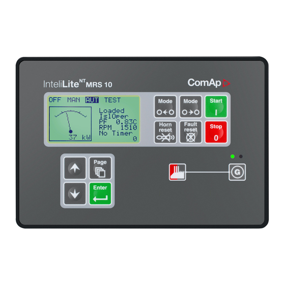
ComAp IL-NT MRS15 Reference Manual

ComAp IL-NT MRS15 Reference Manual

Intelilite nt mrs series, intelilite nt amf series, modular gen-set controller, compact controller for stand-by operating gen-sets
Hide thumbs Also See for IL-NT MRS15:
Table of Contents

Advertisement

NT
InteliLite
InteliLite NT
Modular Gen-set Controller
Compact Controller for Stand-by Operating Gen-sets
(IL-NT-MRS3,4-AMF8,9)
SW version 1.4, October 2008
Copyright © 2008 ComAp s.r.o.
Written by Petr Novák
Prague, Czech Republic
®
MRSx AMFx
ComAp, spol. s r.o.
Kundratka 2359/17, 180 00 Praha 8, Czech Republic
Tel: +420 2 66316661, Fax: +420 2 66316647
E-mail: info@comap.cz, www.comap.cz
Reference Guide

Advertisement

Table of Contents
loading
Need help?

Need help?

Do you have a question about the IL-NT MRS15 and is the answer not in the manual?

Questions and answers

Алексей
March 16, 2025

Как сбросить ошибку ТО, восклицательный знак

Summary of Contents for ComAp IL-NT MRS15

  • Page 1 (IL-NT-MRS3,4-AMF8,9) SW version 1.4, October 2008 Reference Guide ComAp, spol. s r.o. Copyright © 2008 ComAp s.r.o. Kundratka 2359/17, 180 00 Praha 8, Czech Republic Written by Petr Novák Tel: +420 2 66316661, Fax: +420 2 66316647 Prague, Czech Republic...
  • Page 2: Table Of Contents

    Sensor Fail (FLS) ..........................44 Warning (WRN) ..........................44 Shut down (SD)..........................44 ^Mains failure (MF)..........................44 Gen-set Operation States........................47 List of possible events........................47 User Interface ............................49 InteliLite – MRS3,4, AMF8,9, SW version 1.4, ©ComAp – October 2008 IL-NT-MRS3,4-AMF8,9-1.4-Reference Guide.pdf...
  • Page 3 IL-NT RS232 interface (optional card) ....................62 IL-NT RS232-485 interface (optional card) ..................62 IL-NT S-USB interface (optional card) ....................62 IL-NT AOUT8 interface (optional card) ..................... 62 IG-IB ..............................63 InteliLite – MRS3,4, AMF8,9, SW version 1.4, ©ComAp – October 2008 IL-NT-MRS3,4-AMF8,9-1.4-Reference Guide.pdf...
  • Page 4: General Guidelines

    Software IL-NT 1.3 is compatible with IL-NT hardware version 1.3 and older. Symbols Symbols used in this manual: Grounding AC voltage DC voltage point symbol symbol symbol InteliLite – MRS3,4, AMF8,9, SW version 1.4, ©ComAp – October 2008 IL-NT-MRS3,4-AMF8,9-1.4-Reference Guide.pdf...
  • Page 5: Text

    (Symbol ^ before text) valid only for IL-NT AMF8 and AMF9 (icon) Setpoint is password protected Note: ComAp believes that all information provided herein is correct and reliable and reserves the right to update at any time. ComAp does not assume any responsibility for its use unless otherwise expressly undertaken.
  • Page 6: General Description

    Extension modules not supported in IL-NT MRS3/4 and IL-NT AMF8/9. Hint: For detailed information about extension modules used with IL-NT controllers, please see the IL-NT- Accessory Modules manual. InteliLite – MRS3,4, AMF8,9, SW version 1.4, ©ComAp – October 2008 IL-NT-MRS3,4-AMF8,9-1.4-Reference Guide.pdf...
  • Page 7: Il-Nt Rs232 Communication Module

    The following procedure is analogic also for other communication modules. 1. Insert a screwdriver into the slot of the cover. 2. Move the screwdriver to set apart the small cover. Be careful! InteliLite – MRS3,4, AMF8,9, SW version 1.4, ©ComAp – October 2008 IL-NT-MRS3,4-AMF8,9-1.4-Reference Guide.pdf...
  • Page 8 3. Remove the small cover. 4. Break apart the small cover into two pieces. Do not throw away the smaller part! InteliLite – MRS3,4, AMF8,9, SW version 1.4, ©ComAp – October 2008 IL-NT-MRS3,4-AMF8,9-1.4-Reference Guide.pdf...
  • Page 9 5. Take RS 232 communication module. InteliLite – MRS3,4, AMF8,9, SW version 1.4, ©ComAp – October 2008 IL-NT-MRS3,4-AMF8,9-1.4-Reference Guide.pdf...
  • Page 10 When you insert RS 232 communication module, the boot jumper is hidden. For that reason we recommend to use RS 232 communication module with the boot jumper placed on it. See pictures below: RS 232 communication module with the boot jumper. InteliLite – MRS3,4, AMF8,9, SW version 1.4, ©ComAp – October 2008 IL-NT-MRS3,4-AMF8,9-1.4-Reference Guide.pdf...
  • Page 11: Il-Nt Rs232-485 Communication Module

    It is supposed to be used as a service tool. When you need to remove it, grab module in cutouts and pull it up manually. InteliLite – MRS3,4, AMF8,9, SW version 1.4, ©ComAp – October 2008 IL-NT-MRS3,4-AMF8,9-1.4-Reference Guide.pdf...
  • Page 12: Il-Nt Aout8 Gauge Driver Module

    Hint: Use the shielded USB A-B cable with this module! Recommended is ComAp cable – Order code: “ ”. USB-LINK CABLE 1.8M IL-NT AOUT8 Gauge driver module IL-NT AOUT8 is optional plug-in card. Through this card controller can drive up to 8 VDO style industrial/automotive gauges.
  • Page 13: Il-Nt Rd Remote Display Software

    Please see the “IL-NT-RD Remote display software” chapter for more details. IG-IB Internet bridge IG-IB Internet bridge enables InteliLite for Ethernet/Internet communicatons. It is connected to controller via RS232 line. See the InteliCommunication guide for further details. InteliLite – MRS3,4, AMF8,9, SW version 1.4, ©ComAp – October 2008 IL-NT-MRS3,4-AMF8,9-1.4-Reference Guide.pdf...
  • Page 14: Programming Of Il-Nt Controller

    Programming of IL-NT controller Programming is possible only in MAN mode when the engine is not running. Hint: For more information on programing, see LiteEdit Reference Guide. InteliLite – MRS3,4, AMF8,9, SW version 1.4, ©ComAp – October 2008 IL-NT-MRS3,4-AMF8,9-1.4-Reference Guide.pdf...
  • Page 15: User Interface

    ENTER and PAGE button and than press again PAGE. On screen will be displeyed the choice of two different User Interfaces. Please see latest IL-NT Operator Guide for detailed description. InteliLite – MRS3,4, AMF8,9, SW version 1.4, ©ComAp – October 2008 IL-NT-MRS3,4-AMF8,9-1.4-Reference Guide.pdf...
  • Page 16: Il-Nt Terminals

    IL-NT Terminals IL-NT Terminals InteliLite – MRS3,4, AMF8,9, SW version 1.4, ©ComAp – October 2008 IL-NT-MRS3,4-AMF8,9-1.4-Reference Guide.pdf...
  • Page 17 InteliLite – MRS3,4, AMF8,9, SW version 1.4, ©ComAp – October 2008 IL-NT-MRS3,4-AMF8,9-1.4-Reference Guide.pdf...
  • Page 18: Recommended Wiring

    Recommended Wiring AMF – Wiring Diagram InteliLite – MRS3,4, AMF8,9, SW version 1.4, ©ComAp – October 2008 IL-NT-MRS3,4-AMF8,9-1.4-Reference Guide.pdf...
  • Page 19: Mrs - Wiring Diagram

    It is possible to start Volvo and Scania engines via CAN bus. See Engines started via CAN bus. If D+ function is not used connect the D+ terminal to battery positive. InteliLite – MRS3,4, AMF8,9, SW version 1.4, ©ComAp – October 2008 IL-NT-MRS3,4-AMF8,9-1.4-Reference Guide.pdf...
  • Page 20: Stand-By Applications

    Stand-by Applications Contactors (set point MCB Logic = “CLOSE-OFF”) InteliLite – MRS3,4, AMF8,9, SW version 1.4, ©ComAp – October 2008 IL-NT-MRS3,4-AMF8,9-1.4-Reference Guide.pdf...
  • Page 21: Ats With Three Stable Positions (Set Point Mcb Logic = "Close-Off")

    ATS with three stable positions (set point MCB Logic = “CLOSE-OFF”) InteliLite – MRS3,4, AMF8,9, SW version 1.4, ©ComAp – October 2008 IL-NT-MRS3,4-AMF8,9-1.4-Reference Guide.pdf...
  • Page 22: Getting Started

    It is possible to further support the controller by connecting the external capacitor and separating diode or I-LBA module: InteliLite – MRS3,4, AMF8,9, SW version 1.4, ©ComAp – October 2008 IL-NT-MRS3,4-AMF8,9-1.4-Reference Guide.pdf...
  • Page 23 Fuse value and type depends on number of connected devices and wire length. Recommended fuse (not fast) type - T1A. Not fast due to internal capacitors charging during power InteliLite – MRS3,4, AMF8,9, SW version 1.4, ©ComAp – October 2008 IL-NT-MRS3,4-AMF8,9-1.4-Reference Guide.pdf...
  • Page 24: Current Measurement

    10V and RPM are readed only if frequency si higher than 1Hz. Current measurement To ensure proper function Use cables of 2,5mm Use transformers to 5A Connect CT according to following drawings InteliLite – MRS3,4, AMF8,9, SW version 1.4, ©ComAp – October 2008 IL-NT-MRS3,4-AMF8,9-1.4-Reference Guide.pdf...
  • Page 25: Voltage Measurement

    Switchboard lighting strikes protection according standard regulation is expected !!! Current measurement To ensure proper function Use cables of 2,5mm Use transformers to 5A Connect CT according to following drawings. Terminals L2l and L3l are opened. InteliLite – MRS3,4, AMF8,9, SW version 1.4, ©ComAp – October 2008 IL-NT-MRS3,4-AMF8,9-1.4-Reference Guide.pdf...
  • Page 26: Analog Inputs

    User Curves are adjustable in LiteEdit. Each Analog input has separate set points for two level alarm setting. Analog input alarm levels and delay adjust in Basic settings group. InteliLite – MRS3,4, AMF8,9, SW version 1.4, ©ComAp – October 2008 IL-NT-MRS3,4-AMF8,9-1.4-Reference Guide.pdf...
  • Page 27 Fail sensor. “Engine running only” – check this setting if you wish to active protection on analog input only while engine is running, not, when it stops. InteliLite – MRS3,4, AMF8,9, SW version 1.4, ©ComAp – October 2008 IL-NT-MRS3,4-AMF8,9-1.4-Reference Guide.pdf...
  • Page 28 Number of decimal points of AIx Wrn and AIx Sd is the same as the configured number of decimal points of measured value. Binary inputs 4k7 Ω Power Supply Battery InteliLite – MRS3,4, AMF8,9, SW version 1.4, ©ComAp – October 2008 IL-NT-MRS3,4-AMF8,9-1.4-Reference Guide.pdf...
  • Page 29 Binary outputs LOAD Power Supply Battery InteliLite – MRS3,4, AMF8,9, SW version 1.4, ©ComAp – October 2008 IL-NT-MRS3,4-AMF8,9-1.4-Reference Guide.pdf...
  • Page 30: Inputs And Outputs

    In 1.2 version of FW, there is a possibility to function without feedback from GCB and MCB. Binary Inputs – List Rem Start/Stop External request for engine run. AUT mode only. InteliLite – MRS3,4, AMF8,9, SW version 1.4, ©ComAp – October 2008 IL-NT-MRS3,4-AMF8,9-1.4-Reference Guide.pdf...
  • Page 31: Binary Outputs - List

    The output closes prior to the engine start (Prestart) and opens when Starting RPM speed is reached. During Crank Attempts the output is closed too. The output could be used for pre-glow, pre-heat or prelubrication. InteliLite – MRS3,4, AMF8,9, SW version 1.4, ©ComAp – October 2008 IL-NT-MRS3,4-AMF8,9-1.4-Reference Guide.pdf...
  • Page 32 In case of repeated crank attempts the output closes always prior to the other engine start attempts (by Prestart Time) and is opened during crank attempts. InteliLite – MRS3,4, AMF8,9, SW version 1.4, ©ComAp – October 2008 IL-NT-MRS3,4-AMF8,9-1.4-Reference Guide.pdf...
  • Page 33: Analog Inputs

    Any value from controler may be configured to the outputs. Use LiteEdit PC SW to configure corresponding sensor/gauge curve and value selection. InteliLite – MRS3,4, AMF8,9, SW version 1.4, ©ComAp – October 2008 IL-NT-MRS3,4-AMF8,9-1.4-Reference Guide.pdf...
  • Page 34: Setpoints

    Time of closing of the PRE-START output prior to the engine start. Set to zero if you want to leave the output PRE-START open. Step: Range: 0 – 600 s InteliLite – MRS3,4, AMF8,9, SW version 1.4, ©ComAp – October 2008 IL-NT-MRS3,4-AMF8,9-1.4-Reference Guide.pdf...
  • Page 35 Shutdown threshold level for ANALOG INPUT 2 1 °C Step: Range: -100 – 10000 Al2 del Delay for ANALOG INPUT 2 alarm. Step: Range: 0 – 900 s InteliLite – MRS3,4, AMF8,9, SW version 1.4, ©ComAp – October 2008 IL-NT-MRS3,4-AMF8,9-1.4-Reference Guide.pdf...
  • Page 36: Amf Settings

    Mains >V Threshold for mains overvoltage. All three phases are checked. Maximum out of three is used. Step: 1% of Nominal voltage Range: 50 (Mains <V) – 150% InteliLite – MRS3,4, AMF8,9, SW version 1.4, ©ComAp – October 2008 IL-NT-MRS3,4-AMF8,9-1.4-Reference Guide.pdf...
  • Page 37 Mains <f Threshold for mains underfrequency. All three phases are checked. Maximum out of three is used. Step: 0.1% of nominal frequency Range: 50% – 150.0(Mains >)%f InteliLite – MRS3,4, AMF8,9, SW version 1.4, ©ComAp – October 2008 IL-NT-MRS3,4-AMF8,9-1.4-Reference Guide.pdf...
  • Page 38: Ecu-Controlled Engine Support

    The actual list of ECU types is available on ComAp website in "ECU list - x.y.iwe" package. Download this package and import it into LiteEdit in the same way as standard firmware IWE package.
  • Page 39: Values Read From Ecu

    • SAE Truck and Bus Control and Communications Network Standards Manual, SAE HS-1939 Publication • Or refer to corresponding engine manufacturer’s ECU error codes list. Complete list of text diagnostic messages for each ECU can be found in Comap Electronic Engines Support manual. Hint: InteliLite controller doesn’t support J1587 diagnostic line on Volvo engines.
  • Page 40: Analog Inputs

    GCB Close / Open BO ECU PwrRelay BO ECU CommOK (EDCIII) / ECU CommError ( EMSII ) ( ECU inputs need +24V DC for activation ) FUEL LEVEL InteliLite – MRS3,4, AMF8,9, SW version 1.4, ©ComAp – October 2008 IL-NT-MRS3,4-AMF8,9-1.4-Reference Guide.pdf...
  • Page 41 SCANIA S6 Shutdown Warning Emergency stop Rem Start / Stop Alarm Ready To Load MCB Close / Open GCB Close / Open + 24 V DC FUEL LEVEL InteliLite – MRS3,4, AMF8,9, SW version 1.4, ©ComAp – October 2008 IL-NT-MRS3,4-AMF8,9-1.4-Reference Guide.pdf...
  • Page 42 MAINS C.B. GEN C.B. GND ( PIN 20) RS 485 - ( PIN 18) RS 485 + ( PIN 21) TERM2 ( PIN 19) TERM1 ( PIN 22) InteliLite – MRS3,4, AMF8,9, SW version 1.4, ©ComAp – October 2008 IL-NT-MRS3,4-AMF8,9-1.4-Reference Guide.pdf...
  • Page 43: Sensor Specification

    Sensor Specification Sensors are the part of the installation package. You can find detail information on sensors in LiteEdit Reference Guide - IL-NT-AMF-1.3 Reference Guide, IL-NT-MRS-1.3 Reference Guide. InteliLite – MRS3,4, AMF8,9, SW version 1.4, ©ComAp – October 2008 IL-NT-MRS3,4-AMF8,9-1.4-Reference Guide.pdf...
  • Page 44: Alarm Management

    This alarm occurs only in AMF8 and AMF9 Possible mains failure reasons: See List of possible events Hint: Mains failure is not written to alarm list! InteliLite – MRS3,4, AMF8,9, SW version 1.4, ©ComAp – October 2008 IL-NT-MRS3,4-AMF8,9-1.4-Reference Guide.pdf...
  • Page 45 Sensor Fail detection Sensor Fail Fls is detected when measured value is 6 percent out of range. Controller screen displays in this case string #### instead measured value. InteliLite – MRS3,4, AMF8,9, SW version 1.4, ©ComAp – October 2008 IL-NT-MRS3,4-AMF8,9-1.4-Reference Guide.pdf...
  • Page 46 Range of sensor Sensor Range of measurement Senso 100% Failure Failure InteliLite – MRS3,4, AMF8,9, SW version 1.4, ©ComAp – October 2008 IL-NT-MRS3,4-AMF8,9-1.4-Reference Guide.pdf...
  • Page 47: Gen-Set Operation States

    Start Failed Gen-set start failed. ParamFail NONE Wrong checksum of parameters. Happends typically after downloading new firmware or changing of the InteliLite – MRS3,4, AMF8,9, SW version 1.4, ©ComAp – October 2008 IL-NT-MRS3,4-AMF8,9-1.4-Reference Guide.pdf...
  • Page 48 Stop Failed Gen-set stop failed. ChargeAlt Fail Failure of alternator for charging the battery. Wrn ECU Alarm *ECU alarm list is not empty InteliLite – MRS3,4, AMF8,9, SW version 1.4, ©ComAp – October 2008 IL-NT-MRS3,4-AMF8,9-1.4-Reference Guide.pdf...
  • Page 49: User Interface

    This mode is default. For details how to change the User Interface, please see the IL-NT Operator Guide. InteliLite – MRS3,4, AMF8,9, SW version 1.4, ©ComAp – October 2008 IL-NT-MRS3,4-AMF8,9-1.4-Reference Guide.pdf...
  • Page 50: Remote Control And Data Logging

    Required the same voltage potential between GND‘s Battery PC software – LiteEdit On the PC (for direct or modem connection) has to be installed the ComAp’s software package LiteEdit. (based on Windows 95 or newer platform) LiteEdit enables: • read the quantities •...
  • Page 51 10034 Binary 8 Engine Fuel Rate ECU 0,0 L/h 9860 Unsigned Engine Cool Temp ECU 22 °C 9855 Integer 16 Engine IntakeTemp ECU 20 °C 9878 Integer 16 InteliLite – MRS3,4, AMF8,9, SW version 1.4, ©ComAp – October 2008 IL-NT-MRS3,4-AMF8,9-1.4-Reference Guide.pdf...
  • Page 52 Run Hours 0,0 h 8206 Integer 32 Statistics Num Starts 8207 Unsigned Statistics Num E-Stops 11195 Unsigned Statistics Shutdowns 11196 Unsigned IL Info Engine State ##### 8330 Unsigned InteliLite – MRS3,4, AMF8,9, SW version 1.4, ©ComAp – October 2008 IL-NT-MRS3,4-AMF8,9-1.4-Reference Guide.pdf...
  • Page 53 8955 Unsigned IL Info FW Version 8393 Unsigned 8 IL Info Application 8480 Unsigned 8 IL Info FW Branch 8707 Unsigned 8 IL Info PasswordDecode ##### 9090 Unsigned InteliLite – MRS3,4, AMF8,9, SW version 1.4, ©ComAp – October 2008 IL-NT-MRS3,4-AMF8,9-1.4-Reference Guide.pdf...
  • Page 54: Il-Nt-Rd Remote Display Software

    In this moment go to C -> P -> P and select ONTROLLER ROGRAMMING AND CLONING ROGRAMMING proper! firmware you want program to the controller. Choosing the wrong type of firmware InteliLite – MRS3,4, AMF8,9, SW version 1.4, ©ComAp – October 2008 IL-NT-MRS3,4-AMF8,9-1.4-Reference Guide.pdf...
  • Page 55: Il-Nt-Rd Wiring

    Troubles with connection There are few reasons why remote display can not connect with master controller: 1. Not supported type of controller connected (Eg. IGS-NT, ID-DCU, IC-NT, IGS-CU, etc.) InteliLite – MRS3,4, AMF8,9, SW version 1.4, ©ComAp – October 2008 IL-NT-MRS3,4-AMF8,9-1.4-Reference Guide.pdf...
  • Page 56 RxD 2 3 TxD TxD 3 2 RxD GND 5 5 GND Remote RS485 and/or direct RS232 connection HW module: IL-NT-RS232-485 Up to 1000 meters (only with RS485): InteliLite – MRS3,4, AMF8,9, SW version 1.4, ©ComAp – October 2008 IL-NT-MRS3,4-AMF8,9-1.4-Reference Guide.pdf...
  • Page 57 RS232 direct connection with IL-NT-RS232 module on one side and IL-NT- RS232-485 module on the other side. Alternative connection using external RS232-RS422/485 converter: Recommend external converter: InteliLite – MRS3,4, AMF8,9, SW version 1.4, ©ComAp – October 2008 IL-NT-MRS3,4-AMF8,9-1.4-Reference Guide.pdf...
  • Page 58: Function Description

    All ID-Lite standard software from ver. 1.0 • Chosen IL-NT and ID-Lite customer branches the IL-NT-RD software. Some of the future IL-NT, ID-Lite versions may require upgrade of InteliLite – MRS3,4, AMF8,9, SW version 1.4, ©ComAp – October 2008 IL-NT-MRS3,4-AMF8,9-1.4-Reference Guide.pdf...
  • Page 59: Technical Data

    Reverse Power Synchronism Check - Phase Rotation Undercurrent Power Factor Gas (Fuel) Level • • • • Note: Not available • Available Fixed setting Shortcurrent only Power supply InteliLite – MRS3,4, AMF8,9, SW version 1.4, ©ComAp – October 2008 IL-NT-MRS3,4-AMF8,9-1.4-Reference Guide.pdf...
  • Page 60: Operating Conditions

    0 – 480 VAC phase to phaseMaximal measured voltage 340 VAC phase to neutral 600 VAC phase to phase Input resistance 0.6 MΩ phase to phase 0.3 MΩ phase to neutral InteliLite – MRS3,4, AMF8,9, SW version 1.4, ©ComAp – October 2008 IL-NT-MRS3,4-AMF8,9-1.4-Reference Guide.pdf...
  • Page 61: Binary Inputs And Outputs

    BELDEN (see http://www.belden.com): • 3082A DeviceBus for Allen-Bradley DeviceNet • 3083A DeviceBus for Allen-Bradley DeviceNet • 3086A DeviceBus for Honeywell SDS • 3087A DeviceBus for Honeywell SDS InteliLite – MRS3,4, AMF8,9, SW version 1.4, ©ComAp – October 2008 IL-NT-MRS3,4-AMF8,9-1.4-Reference Guide.pdf...
  • Page 62: Il-Nt Rs232 Interface (Optional Card)

    USB-LINK CABLE 1.8M– ComAp A-B USB cable. IL-NT AOUT8 interface (optional card) Plugs into IL-NT controller EXTENSION MODULE port. Number of PWM outputs PWM frequency 250Hz Maximum current 0.5 A InteliLite – MRS3,4, AMF8,9, SW version 1.4, ©ComAp – October 2008 IL-NT-MRS3,4-AMF8,9-1.4-Reference Guide.pdf...
  • Page 63: Ig-Ib

    95 x 96 x 43 mm , DIN rail (35 mm) mounted Interface to controller RS232 Interface to modem RS232 Interface to Ethernet RJ45 (10baseT) Operating temperature -30..+70 Storage temperature -30..+70 InteliLite – MRS3,4, AMF8,9, SW version 1.4, ©ComAp – October 2008 IL-NT-MRS3,4-AMF8,9-1.4-Reference Guide.pdf...

This manual is also suitable for:

Il-nt mrs10Il-nt amf20Il-nt amf25

Table of Contents

Save PDF