Table of Contents
Advertisement
Advertisement
Table of Contents

Subscribe to Our Youtube Channel
Related Manuals for ACME TB-1010QW II


Summary of Contents for ACME TB-1010QW II
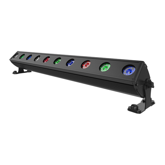
- Page 1 TB-1010QW II User Manual Please read the instruction carefully before use...
-
Page 2: Table Of Contents
CONTENTS 1. Safety Instructions ....................2 2. Technical Specifications ..................3 3. How To Set The Unit ....................4 3.1 Control panel ....................4 3.2 Main Functions ....................5 4. How to Control the Unit ..................10 4.1 DMX 512 Connections ..................10 4.2 DMX Controller .................... -
Page 3: Safety Instructions
1. Safety Instructions Please read the instructions carefully which includes important information about the installation, operation and maintenance. WARNING Please keep this User Guide for future consultation. If you sell the unit to another user, be sure that they also receive this instruction booklet. ... -
Page 4: Technical Specifications
Warning: To prevent or reduce the risk of electrical shock or fire, do not expose the unit to rain or moisture. The housing and lenses must be replaced if they are visibly damaged. Installation: The fixture should be mounted via its screw holes on the bracket. Always ensure that the unit is firmly fixed to avoid vibration and slipping while operating and make sure that the structure to which you are attaching the unit is secure and is able to support a weight of 10 times of the fixtures weight. -
Page 5: How To Set The Unit
Photometrics Diagram Distance(m) 10° 1025 9227 4374 ° Diameter(m) 0 32 0 63 0.96 1 28 3. How To Set The Unit 3.1 Control panel 1. DMX IN: Water proof 3-pin XLR connectors for DMX 512 operation; 2. POWER IN: Water proof connectors for power input;... -
Page 6: Main Functions
To go forward in the selected functions ENTER To confirm the selected functions 5. POWER OUT: Water proof connectors for power output; 6. DMX OUT: Water proof connectors for DMX 512 operation, 3-pin XLR cable to output DMX signal; 3.2 Main Functions To select any functions, press the MENU button until the required one is shown on the display. - Page 7 DMX ADDRESS CHANNEL MODE SHOW MODE DIMMER SPEED BLACKOUT MODE MANUAL TEST MENU WHITE BALANCE PASSWORD LOCK NORMAL DISPLAY INVERSION AUTO TEST LED DISPLAY FIXTURE TEMPERATURE FIXTURE USE HOURS FIRMWARE VERSION...
- Page 8 DMX 512 ADDRESS To select , press the ENTER button to show DMX ADDRESS on the display. Use the DOWN/UP buttons to adjust the address from 1 to 512. Once the address has been selected, press the ENTER button to setup. To go back to the functions without any changes press the MENU button again. Press and hold the MENU button for about one second or wait for 7 seconds to exit the menu mode.
- Page 9 MANUAL TEST To select , press the ENTER button to show MANUAL TEST on the display. Use the DOWN/UP button to select (red), (green), (blue), (white), (dimmer) or (strobe) on the display. Once the mode has been selected, press the ENTER button to confirm. Use the DOWN/UP buttons to specify a value for the chosen effect from 0 to 255.
- Page 10 DISPLAY INVERSE To select , press the ENTER button to show DISPLAY INVERSE on the display, and press the ENTER button again, it will show the (inversion). To go back to the functions without any changes press the MENU button. AUTO TEST To select , press the ENTER button to show AUTO TEST on the display and the unit will run a...
-
Page 11: How To Control The Unit
seconds to exit the current mode. SOFTWARE VERSION To select , press the ENTER button to show SOFTWARE VERSION on the display and the display will show the version of software of the unit . To go back to the functions without any changes press the MENU button again. -
Page 12: Dmx Controller
3. At last fixture, the DMX cable has to be terminated with a terminator to reduce signal errors. Solder a 120Ω, 1/4W resistor between pin 2(DMX-) and pin 3(DMX+) into a 3-pin XLR-plug and plug it in the DMX-output of the last fixture. 4. -
Page 13: Dmx 512 Configurations
4.3 DMX 512 Configurations 4 Channels Mode: CHANNEL VALUE FUNCTION 000-255 0% ~ 100% GREEN 000-255 0% ~ 100% BLUE 000-255 0% ~ 100% WHITE 000-255 0% ~ 100% 5 Channels Mode: CHANNEL VALUE FUNCTION 000-255 0% ~ 100% GREEN 000-255 0% ~ 100% BLUE... - Page 14 7 Channels Mode: CHANNEL VALUE FUNCTION 000-255 0% ~ 100% GREEN 000-255 0% ~ 100% BLUE 000-255 0% ~ 100% WHITE 000-255 0% ~ 100% COLOR 000-007 008-015 Color 1 016-023 Color 2 024-030 Color 3 031-038 Color 4 039-046 Color 5 047-054 Color 6...
- Page 15 241-247 Color 31 248-255 Color 32 DIMMER 000-255 0% ~ 100% STROBE 000-007 008-015 Open 016-131 Strobe, slow fast 132-139 Open 140-181 Slow open, fast close 182-189 Open 190-231 Slow close, fast open 232-239 Open 240-247 Random strobe 248-255 Open 40 Channels Mode: CHANNEL...
-
Page 16: Troubleshooting
BLUE10 000-255 0% ~ 100% WHITE10 000-255 0% ~ 100% 5. Troubleshooting Following are a few common problems that may occur during operation. Here are some suggestions for easy troubleshooting: Problem Possible Cause Action The unit does not work, Incorrect power cable Check the connection of no light. -
Page 17: Fixture Cleaning
6. Fixture Cleaning The cleaning must be carried out periodically to optimize light output. Cleaning frequency depends on the environment in which the fixture operates: damp, smoky or particularly dirty surrounding can cause greater accumulation of dirt on the unit’s optics. ... - Page 19 Declaration of Conformity We declare that our products (lighting equipments) comply with the following specification and bears CE mark in accordance with the provision of the Electromagnetic Compatibility (EMC) Directive 89/336/EEC. EN55103-1: 2009 ; EN55103-2: 2009; EN62471: 2008; EN61000-3-2: 2006 + A1:2009 + A2:2009; EN61000-3-3: 2008. &...
- Page 20 Innovation, Quality, Performance...
Need help?
Do you have a question about the TB-1010QW II and is the answer not in the manual?
Questions and answers