Table of Contents
Advertisement
Quick Links
Advertisement
Table of Contents

Related Manuals for ACME LED-MS150


Summary of Contents for ACME LED-MS150
-
Page 1: User Manual
LED-MS150 User Manual Please read the instruction carefully before use... -
Page 2: Table Of Contents
CONTENTS 1. Safety Instruction ....................2 2. Technical Specifications ..................3 3. How To Set The Unit ....................4 3.1 Fixture Overview ....................4 3.2 Gobo Wheel ..................... 6 3.3 Main Function ....................6 3.4 Home Position Adjustment ................12 4. -
Page 3: Safety Instruction
1. Safety Instruction Please read the instruction carefully which includes important information about the installation, usage and maintenance. WARNING Please keep this User Guide for future consultation. If you sell the unit to another user, be sure that they also receive this instruction manual. ... -
Page 4: Technical Specifications
moisture. DO NOT open the unit within five minutes after switching off. The housing, the lenses, or the ultraviolet filter must be replaced if they are visibly damaged. Caution There are no user serviceable parts inside the unit. DO NOT open the housing or attempt any repairs yourself. -
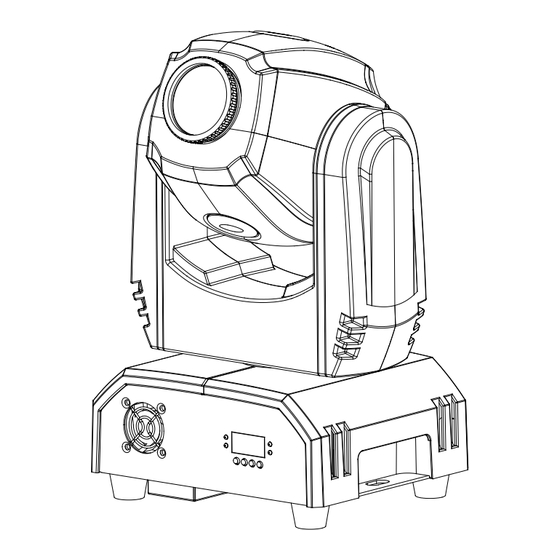
Page 5: How To Set The Unit
Weight: 5.3Kgs Dimension: 212 x 174 x 352mm 3. How To Set The Unit 3.1 Fixture Overview 1. LED: DMX input present MASTER Master Mode SLAVE Slave Mode SOUND Flashing Sound activation 2. Button: MENU To select the programming functions... - Page 6 DOWN To go backward in the selected functions To go forward in the selected functions ENTER To confirm the selected functions 3. LED Display: Used to show the various menus and the selected functions. 4. DMX IN/OUT: For DMX512 links, use 3-pin XLR plug cable to link the unit together. 5.
-
Page 7: Gobo Wheel
3.2 Gobo Wheel Rotation gobo wheel DANGER! Install/change the gobo-wheel with the device switched off only. 3.3 Main Function To select any of the given functions, press the MENU button up to when the required one is showing on the display. Select the function by ENTER button and the display will blink. Use DOWN and UP button to change the mode. - Page 8 SLAVE MODE MENU SOUND MODE SOUND SENSE BLACKOUT MODE NORMAL DISPLAY INVERSION LED DISPLAY ON LED DISPLAY OFF NORMAL PAN INVERSION NORMAL TILT INVERSION TEST TEMPERATURE FIXTURE HOURS SOFTWARE VERSION RESET...
- Page 9 DMX 512 ADDRESS To select the , press the ENTER button to show the DMX ADDRESS on the display. Use the DOWN/UP button to adjust the address from 1 to 512. Once the address has been selected, press the ENTER button to setup, to go back to the functions without any changes press the MENU button again.
- Page 10 DIMMER MODE To select , press the ENTER button to show DIMMER MODE on the display. Use the DOWN/UP buttons to select the (Dimmer 1), (Dimmer2), (Dimmer 3) or (Dimmer 4) mode. Once the show has been selected, press the ENTER button to setup. To go back to the functions without any changes press the MENU button again.
- Page 11 BLACKOUT MODE To select the , press the ENTER button to show the BALCKOUT MODE on the display. Use the DOWN/UP button to select the (normal) or (blackout) mode. Once the mode has been selected, press the ENTER button to setup, to go back to the functions without any changes press the MENU button again.
- Page 12 TILT INVERSION To select the , press the ENTER button to show the TILT INVERSIO on the display. Use the DOWN/UP button to select the (normal) or (tilt inversion) mode. Once the mode has been selected, press the ENTER button to setup, to go back to the functions without any changes press the MENU button again.
-
Page 13: Home Position Adjustment
changes press the MENU button again. Hold and press the MENU button for one second or wait for one minute to exit the menu mode. RESET , press the ENTER button to show the RESET on the display. Press the ENTER To select the button and all channels of the unit will return to their standard position. -
Page 14: How To Control The Unit
Press the MENU button to exit. — Color home position adjustment To select the , press the ENTER button to show the COLOR OFFSET on the display. Use the DOWN and UP button to adjust the value from -127 to 127, press the ENTER button to store. Press the MENU button to exit. -
Page 15: Easy Controller
In slave mode, means the unit works normally and means 2-light show. In order to create a great light show, you can set on the second unit to get contrast movement to each other, even if you have two units only. 4.2 Easy Controller The easy remote control is used only in master/slave mode. -
Page 16: Dmx512 Configuration
5. DMX512 Configuration 8 Channels Mode: CHANNEL VALUE FUNCTION PAN: 000-255 0 - 540° TILT: 000-255 0 - 270° STROBE: 000-007 Black out 008-015 Open 016-131 Strobe, Slow to Fast 132-139 Open 140-181 Slow Open, Fast Close 182-189 Open 190-231 Fast Open, Slow Close 232-239 Open... - Page 17 128-189 Clockwise Color Scroll, Fast to Slow 190-193 Stop 194-255 Counter Clockwise Color Scroll, Slow to Fast GOBO: 000-009 White 010-018 Gobo1 019-027 Gobo2 028-036 Gobo3 037-045 Gobo4 046-054 Gobo5 055-063 Gobo6 064-073 White shaking 074-082 Gobo1 shaking 083-091 Gobo2 shaking 092-100 Gobo3 shaking 101-110...
- Page 18 250-255 Sound Active 10 Channels Mode: CHANNEL VALUE FUNCTION PAN: 000-255 0°- 540° 000-255 PAN FINE TILT: 000-255 0 - 270° 000-255 TILT FINE STROBE: 000-007 Black out 008-015 Open 016-131 Strobe, Slow to Fast 132-139 Open 140-181 Slow Open, Fast Close 182-189 Open 190-231...
- Page 19 000-009 White 010-018 Gobo1 019-027 Gobo2 028-036 Gobo3 037-045 Gobo4 046-054 Gobo5 055-063 Gobo6 064-073 White shaking 074-082 Gobo1 shaking 083-091 Gobo2 shaking 092-100 Gobo3 shaking 101-110 Gobo4 shaking 111-119 Gobo5 shaking 120-127 Gobo6 shaking 128-189 Clockwise Gobo Scroll, Fast to Slow 190-193 Stop 194-255...
-
Page 20: Dmx Connection
6. DMX Connection Unit 1 Unit 2 Unit 3 Unit 4 1. At last unit, the DMX cable has to be terminated with a terminator. Solder a 120 ohm 1/4W resistor between pin 2(DMX-) and pin 3(DMX+) into a 3-pin XLR-plug and plug it in the DMX-output of the last unit. -
Page 21: Troubleshooting
6. 3 pin XLR connectors are more popular than 5 pin XLR. 3 pin XLR: Pin 1: GND, Pin 2: Negative signal (-), Pin 3: Positive signal (+) 5 pin XLR: Pin 1: GND, Pin 2: Negative signal (-), Pin 3: Positive signal (+) Pin 4/5: Not used. -
Page 22: Fixture Cleaning
2. Check microphone to see if it is good by tapping the microphone E. One of the channels is not working well 1. The stepper motor might be damaged or the cable connected to the PCB is broken. 2. The motor’s drive IC on the PCB might be out of condition 8. -
Page 23: Declaration Of Conformity
Declaration of Conformity We declare that our products (lighting equipments) comply with the following specification and bears CE mark in accordance with the provision of the Electromagnetic Compatibility (EMC) Directive 89/336/EEC. EN55103-1: 2009 ; EN55103-2: 2009; EN62471: 2008; EN61000-3-2: 2006 + A1:2009 + A2:2009; EN61000-3-3: 2008. &... - Page 24 Innovation, Quality, Performance...
Need help?
Do you have a question about the LED-MS150 and is the answer not in the manual?
Questions and answers