Table of Contents
Advertisement
Quick Links
Download this manual
See also:
User Manual
Advertisement
Table of Contents

Subscribe to Our Youtube Channel
Related Manuals for Automationdirect.com DL05


Summary of Contents for Automationdirect.com DL05
- Page 1 DL05 Micro PLC User Manual Volume 1 of 2 Manual Number: D0-USER-M...
- Page 3 Copyright 2016, Automationdirect.com Incorporated All Rights Reserved No part of this manual shall be copied, reproduced, or transmitted in any way without the prior, written consent of Automationdirect.com Incorporated. AutomationDirect retains the exclusive rights to all information included in this document.
- Page 4 Nulle partie de ce manuel ne doit être copiée, reproduite ou transmise de quelque façon que ce soit sans le consentement préalable écrit de la société Automationdirect.com Incorporated. AutomationDirect conserve les droits exclusifs à l’égard de tous les renseignements contenus dans le présent document.
- Page 5 DL05 M PLc USER MANUAL icro Please include the Manual Number and the Manual Issue, both shown below, when communicating with Technical Support regarding this publication. Manual Number: D0-USER-M Issue: Sixth Edition, Rev. D Issue Date: 10/17 Publication History Issue...
-
Page 7: Table Of Contents
DL05 Micro PLC Components The DL05 Micro PLC Family DirectSOFT Programming for Windows™ Handheld Programmer I/O Selection Quick Chart Quick Start for PLC Checkout and Programming Steps to Designing a Successful System 1-10 Questions and Answers about DL05 Micro PLCs 1-12... - Page 8 Fuse Protection for Input and Output Circuits 2-13 I/O Point Numbering 2-13 System Wiring Strategies 2-14 PLC Isolation Boundaries 2-14 Connecting Operator Interface Devices 2-15 Connecting Programming Devices 2-15 Sinking/Sourcing Concepts 2-16 DL05 Micro PLC User Manual, 6th Edition, Rev. D...
- Page 9 D0–05DA I/O Wiring Diagram 2-42 D0–05DR-D I/O Wiring Diagram 2-44 D0–05DD–D I/O Wiring Diagram 2-46 Glossary of Specification Terms 2-48 Chapter 3: CPU Specifications and Operation Introduction DL05 CPU Features CPU Specifications DL05 Micro PLC User Manual, 6th Edition, Rev. D...
- Page 10 3-14 Write Outputs 3-15 Diagnostics 3-15 I/O Response Time 3-15 Is Timing Important for Your Application? 3-15 Normal Minimum I/O Response 3-15 Normal Maximum I/O Response 3-16 Improving Response Time 3-17 DL05 Micro PLC User Manual, 6th Edition, Rev. D...
- Page 11 Special Relays (SP Data Type) 3-25 DL05 System V-memory 3-26 System Parameters and Default Data Locations (V Data Type) 3-26 DL05 Memory Map Table 3-28 DL05 Aliases 3-29 X Input Bit Map 3-30 DL05 Micro PLC User Manual, 6th Edition, Rev. D...
- Page 12 Modbus Function Codes Supported Determining the Modbus Address If Your Host Software Requires the Data Type and Address... Example 1: V2100 4-10 Example 2: Y20 4-10 Example 3: T10 Current Value 4-10 DL05 Micro PLC User Manual, 6th Edition, Rev. D...
- Page 13 Using Boolean Instructions END Statement Simple Rungs Normally Closed Contact Contacts in Series Midline Outputs Parallel Elements Joining Series Branches in Parallel Joining Parallel Branches in Series Combination Networks Comparative Boolean DL05 Micro PLC User Manual, 6th Edition, Rev. D...
- Page 14 Using the Accumulator 5-48 Copying Data to the Accumulator 5-48 Changing the Accumulator Data 5-49 Using the Accumulator Stack 5-50 Using Pointers 5-51 Logical Instructions (Accumulator) 5-60 Math Instructions 5-68 viii DL05 Micro PLC User Manual, 6th Edition, Rev. D...
- Page 15 5-111 Data Label Example 5-113 Intelligent I/O Instructions 5-118 Network Instructions 5-120 Intelligent Box (IBox) Instructions 5-124 (IBOX) Instructions List Chapter 6: Drum Instruction Programming DL05 Drum Introduction Purpose Drum Terminology DL05 Micro PLC User Manual, 6th Edition, Rev. D...
- Page 16 Timed Drum with Discrete Outputs (DRUM) 6-12 Event Drum (EDRUM) Instruction 6-14 Program Using the Handheld Programmer 6-16 PLUS Chapter 7: RLL Stage Programming Introduction to Stage Programming Overcoming “Stage Fright” DL05 Micro PLC User Manual, 6th Edition, Rev. D...
- Page 17 Add Emergency Stop Feature 7-14 Exclusive Transitions 7-14 Stage Program Design Considerations 7-15 Stage Program Organization 7-15 How Instructions Work Inside Stages 7-16 Using a Stage as a Supervisory Process 7-17 DL05 Micro PLC User Manual, 6th Edition, Rev. D...
- Page 18 Introduction to PID Control What is PID Control? Introducing DL05 PID Control Process Control Definitions PID Loop Operation Position Form of the PID Equation Step Bias Proportional to Step Change in SP 8-10 DL05 Micro PLC User Manual, 6th Edition, Rev. D...
- Page 19 Open-Loop Test 8-40 Manual Tuning Procedure 8-41 Auto Tuning Procedure 8-45 Use Direct SOFT Data View with PID View 8-49 Open a New Data View Window 8-49 Open PID View 8-50 xiii DL05 Micro PLC User Manual, 6th Edition, Rev. D...
- Page 20 Program the Ramp/Soak Control in Relay Ladder 8-63 Test the Profile 8-64 Cascade Control 8-65 Introduction 8-65 Cascaded Loops in the DL05 CPU 8-66 Tuning Cascaded Loops 8-67 Time-Proportioning Control 8-68 On/Off Control Program Example 8-69 DL05 Micro PLC User Manual, 6th Edition, Rev. D...
- Page 21 Fatal Errors Non-fatal Errors V-memory Error Code Locations Special Relays (SP) Corresponding to Error Codes DL05 Micro PLC Error Codes Program Error Codes CPU Indicators RUN Indicator CPU Indicator Communications Problems DL05 Micro PLC User Manual, 6th Edition, Rev. D...
- Page 22 Jumper Selects Write Enable or Disable 10-2 Low Battery Alert 10-2 Clock/Calendar 10-2 Specifications 10-2 New Ladder Instructions 10-2 Error Code Changes 10-2 Setting the Write Enable/Disable Jumper 10-3 Write Enable 10-3 Write Disable 10-3 DL05 Micro PLC User Manual, 6th Edition, Rev. D...
- Page 23 10-11 Removing and Replacing the Battery 10-11 Specifications and Agency Approvals 10-12 Clock/Calendar Instructions 10-13 Date (DATE) 10-13 Time (TIME) 10-14 Move Memory Cartridge / Load Label (MOVMC) (LDLBL) 10-15 xvii DL05 Micro PLC User Manual, 6th Edition, Rev. D...
-
Page 24: Introduction
AUX 53 Display Scan Time AUX 54 Initialize Scratchpad AUX 55 Set Watchdog Timer AUX 56 CPU Network Address AUX 57 Set Retentive Ranges AUX 58 Test Operations AUX 59 Bit Override xviii DL05 Micro PLC User Manual, 6th Edition, Rev. D... - Page 25 A-10 AUX 83 Lock CPU A-10 Appendix B: DL05 Error Codes DL05 Error Codes Appendix C: Instruction Execution Times Introduction V-memory Data Registers V-memory Bit Registers How to Read the Tables DL05 Micro PLC User Manual, 6th Edition, Rev. D...
- Page 26 DL05 PLC Special Relays Appendix E: High-speed Input and Pulse Output Features Introduction Built-in Motion Control Solution Availability of HSIO Features Dedicated High- Speed I/O Circuit Wiring Diagrams for Each HSIO Mode DL05 Micro PLC User Manual, 6th Edition, Rev. D...
- Page 27 Symptom: The counter counts but the presets do not function. E-17 Symptom: The counter counts up but will not reset. E-17 Mode 20: Quadrature Counter E-18 Purpose E-18 Functional Block Diagram E-18 Quadrature Encoder Signals E-18 Wiring Diagram E-19 DL05 Micro PLC User Manual, 6th Edition, Rev. D...
- Page 28 Trapezoidal Profile Defined E-30 Registration and Home Search Profiles Defined E-30 Velocity Profile Defined E-30 Trapezoidal Profile Operation E-31 Trapezoidal Profile Applications E-31 Trapezoidal Profile Program Example E-32 Preload Position Value E-33 xxii DL05 Micro PLC User Manual, 6th Edition, Rev. D...
- Page 29 Pulse Catch Timing Parameters E-52 Setup for Mode 50 E-53 X Input Configuration E-53 Pulse Catch Program Example E-54 Mode 60: Discrete Inputs with Filter E-55 Purpose E-55 Functional Block Diagram E-55 xxiii DL05 Micro PLC User Manual, 6th Edition, Rev. D...
- Page 30 Appendix I: Numbering System Introduction Binary Numbering System Hexadecimal Numbering System Octal Numbering System Binary Coded Decimal (BCD) Numbering System Real (Floating Point) Numbering System BCD/Binary/Decimal/Hex/Octal - What is the Difference? xxiv DL05 Micro PLC User Manual, 6th Edition, Rev. D...
- Page 31 Equi–potential Grounding Communications and Shielded Cables Analog and RS232 Cables Multidrop Cables Shielded Cables within Enclosures Analog Modules and RF Interference Network Isolation DC Powered Versions Items Specific to the DL05 J-10 DL05 Micro PLC User Manual, 6th Edition, Rev. D...
- Page 32 Step 3: Specify Master Memory Area K-10 Step 4: Specify Slave Memory Area K-11 Communications from a Ladder Program K-12 Multiple Read and Write Interlocks K-12 Modbus RTU Communications K-13 xxvi DL05 Micro PLC User Manual, 6th Edition, Rev. D...
- Page 33 Introduction....................1–2 Conventions Used..................1–3 DL05 Micro PLC Components..............1–4 Programming Methods................1–4 I/O Selection Quick Chart................. 1–5 Quick Start for PLC Checkout and Programming........1–6 Steps to Designing a Successful System..........1–10 Questions and Answers about DL05 Micro PLCs........1–12...
-
Page 34: The Purpose Of This Manual
Specifications”, and proceed on to other chapters as needed. Be sure to keep this manual handy for reference when you run into questions. If you are a new DL05 customer, we suggest you read this manual completely so you can understand the wide variety of features in the DL05 family of products. -
Page 35: Conventions Used
Key Topics for Each Chapter HAPTER Getting Started The beginning of each chapter will list the key topics that can be found in that chapter. In This Chapter... General Information ..............1-2 Specifications ................1-4 DL05 Micro PLC User Manual, 6th Edition, Rev. D... -
Page 36: Dl05 Micro Plc Components
Units with DC outputs offer selectable pulse output capability on the first and second output points. All DL05 Micro PLCs offer a large amount of program memory, a substantial instruction set and advanced diagnostics. Details of these features and more are covered in Chapter 3, CPU Specifications and Operation. -
Page 37: Handheld Programmer
In several instances a particular Input or Output circuit can interface to either DC or AC voltages, or both sinking and sourcing circuit arrangements. Check this chart carefully to find the proper DL05 Micro PLC to interface to the field devices in your application. -
Page 38: Quick Start For Plc Checkout And Programming
It is only intended to give you a general picture of what you will need to do to get your system powered-up. Step 1: Unpack the DL05 Equipment Unpack the DL05 and gather the parts necessary to build this demonstration system. The recommended components are: • DL05 Micro PLC •... - Page 39 DL05 when wiring the switches. Only use UL-approved switches rated for at least 250VAC, 1A for AC inputs. Firmly mount the switches before using. oggle Switches, UL Listed DL05 Micro PLC User Manual, 6th Edition, Rev. D...
- Page 40 Chapter 1: Getting Started Step 3: Connect the Power Wiring Connect the power input wiring for the DL05. Observe all precautions stated earlier in this manual. For more details on wiring, see Chapter 2 on Installation, Wiring, and Specifications. When the wiring is complete, close the connector covers. Do not apply power at this time.
- Page 41 Handheld Programmer, make sure the CPU is in Program Mode (the RUN LED on the front of the DL05 should be off). If the RUN LED is on, use the MODE key on the Handheld Programmer to put the PLC in Program Mode. Enter the following keystrokes on the Handheld Programmer.
-
Page 42: Steps To Designing A Successful System
DL05 system Power Up processes information. This involves not only program execution steps, but also involves Initialize Hardware the various modes of operation and memory layout characteristics. 1-10 DL05 Micro PLC User Manual, 6th Edition, Rev. D... - Page 43 Chapter 1: Getting Started Step 6: Review the Programming Concepts The DL05 PLC instruction set provides for three main approaches to solving the application program, depicted in the figure below. • RLL diagram-style programming is the best tool for solving boolean logic and general CPU register/accumulator manipulation.
-
Page 44: Questions And Answers About Dl05 Micro Plcs
Go to AutomationDirect.com for more information. Q. Is the DL05 expandable? A. No, the DL05 series are stand-alone PLCs with one slot for the installation of an available option module. They do not have expansion bases, such as our DL205 system which has expansion bases, yet are very compact and affordable. - Page 45 A. Port 1: The port is RS-232, fixed at 9600 baud, and uses the proprietary K-sequence protocol. The DL05 can also connect to Modbus RTU and DirectNET networks as a slave device through port 1. The port communicates with the following devices: •...
- Page 46 Chapter 1: Getting Started Notes 1-14 DL05 Micro PLC User Manual, 6th Edition, Rev. D...
- Page 47 IrIng irinG pecIfIcatIons PecificaTions In this Chapter Safety Guidelines..................2–2 Orientation to DL05 Front Panel.............. 2–5 Mounting Guidelines................. 2–7 Wiring Guidelines..................2–11 System Wiring Strategies................ 2–14 Wiring Diagrams and Specifications............2–32 Glossary of Specification Terms.............. 2–48...
-
Page 48: Chapter 2: Installation, Wiring, And Specification
• Local and State Agencies — many local governments and state governments have additional requirements above and beyond those described in the NEC Handbook. Check with your local Electrical Inspector or Fire Marshall office for information. DL05 Micro PLC User Manual, 6th Edition, Rev. D... -
Page 49: Three Levels Of Protection
MCR circuit to drop the PLC I/O power in case of a PLC failure (memory error, I/O communications error, etc.). Use E-Stop and Master Relay Guard Master Power On E STOP Link Relay Guard Line Switc Emergency Stop to Output ommons Arbor nput ommons optional DL05 Micro PLC User Manual, 6th Edition, Rev. D... -
Page 50: Emergency Power Disconnect
Detect damage. Retract WARNING: The control program must not be the only form of protection for any problems that may result in a risk of personal injury or equipment damage. DL05 Micro PLC User Manual, 6th Edition, Rev. D... -
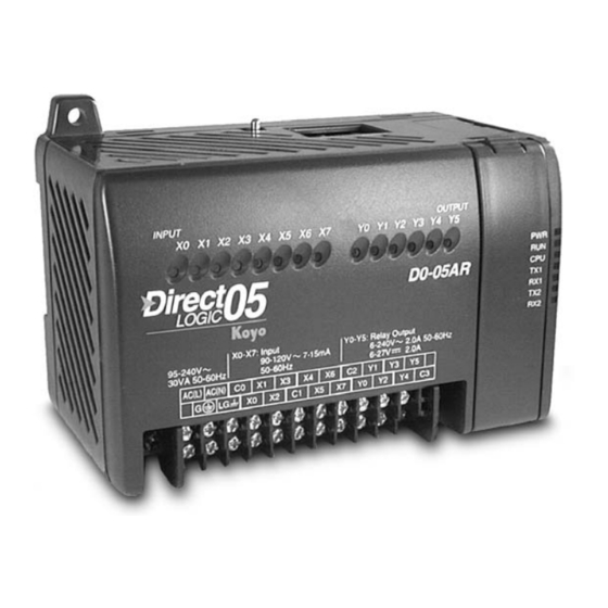
Page 51: Orientation To Dl05 Front Panel
Chapter 2: Installation, Wiring, and Specifications Orientation to DL05 Front Panel Most connections, indicators, and labels on the DL05 Micro PLCs are located on its front panel. The communication ports are located on the top side of the PLC. Please refer to the drawing below. -
Page 52: Connector Removal
Chapter 2: Installation, Wiring, and Specifications Connector Removal All of the terminals for the DL05 are contained on one connector block. In some instances, it may be desirable to remove the connector block for easy wiring. The connector is designed for easy removal with just a small screwdriver. -
Page 53: Mounting Guidelines
• Enclosure Selection and Component Dimensions Unit Dimensions The following diagram shows the outside dimensions and mounting hole locations for all versions of the DL05. Make sure you follow the installation guidelines to allow proper spacing from other components. 0.39"... -
Page 54: Panel Layout & Clearances
4. The ground terminal on the DL05 base must be connected to a single point ground. Use copper stranded wire to achieve a low impedance. Copper eye lugs should be crimped and soldered to the ends of the stranded wire to ensure good surface contact. -
Page 55: Using Din Rail Mounting Rails
7. Evaluate any installations where the ambient temperature may approach the lower or upper limits of the specifications. If you suspect the ambient temperature will not be within the operating specification for the DL05 system, measures such as installing a cooling/heating source must be taken to get the ambient temperature within the range of specifications. -
Page 56: Environmental Specifications
Chapter 2: Installation, Wiring, and Specifications Environmental Specifications The following table lists the environmental specifications that generally apply to DL05 Micro PLCs. The ranges that vary for the Handheld Programmer are noted at the bottom of this chart. Certain output circuit types may have derating curves, depending on the ambient temperature and the number of outputs ON. -
Page 57: Wiring Guidelines
Chapter 2: Installation, Wiring, and Specifications Wiring Guidelines Connect the power input wiring for the DL05. Observe all precautions stated earlier in this manual. Follow the guidelines in this chapter. When the wiring is complete, close the connector covers. Do not apply power at this time. -
Page 58: External Power Source
AC failures. Typically, the main bus is fused at a higher level than the branch device, which in this case is the DL05. The recommended fuse size for the branch circuit to the DL05 is 1A, such as AutomationDirect’s AGC1, fast-acting fuse. -
Page 59: Fuse Protection For Input And Output Circuits
8 or 16, depending on the number of points in an I/O group. For the DL05 the eight inputs use reference numbers X0 – X7. The six output points use references Y0 – Y5. -
Page 60: System Wiring Strategies
Discrete outputs Circuit Isolation Isolation Programming Device or Boundary Boundary Operator Interface The next figure shows the internal layout of DL05 PLCs, as viewed from the front panel. To programming device or operator interface DL05 2 Comm. Ports Main Power... -
Page 61: Connecting Operator Interface Devices
AC power. However, some small operator interface devices, such as the DV-1000 Data Access Unit, may be powered directly from the DL05 Micro PLC. Connect the DV-1000 to communication port 1 on the DL05 Micro PLC with a DV-1000CBL. -
Page 62: Sinking/Sourcing Concepts
By applying the circuit principle above to the four possible combinations of input/output sinking/sourcing types, we have the four circuits as shown below. DL05 Micro PLCs provide all except the sourcing output I/O circuit types. Sinking Input... -
Page 63: I/O "Common" Terminal Concepts
The following label is for DC output versions. One common is provided for all of the outputs and the terminal on the bottom right accepts power for the output stage. AC(L) AC(N) DL05 Micro PLC User Manual, 6th Edition, Rev. D 2-17... -
Page 64: Connecting Dc I/O To Solid State Field Devices
Solid State Input Sensors The DL05’s DC inputs are flexible in that they detect current flow in either direction, so they can be wired as either sourcing or sinking. In the following circuit, a field device has an open- collector NPN transistor output. - Page 65 P pull-up (in watts), in order to size R pull-up properly. The drawing below shows the actual wiring of the DL05 Micro PLC to the supply and pull-up resistor. Common Output – Supply DL05 Micro PLC User Manual, 6th Edition, Rev. D...
-
Page 66: Relay Output Wiring Methods
PLC. Note that each group is isolated from the other group of outputs. Common Common In the circuit below, all loads use the same AC power supply which powers the DL05 PLC. In this example, all commons are connected together. Line... -
Page 67: Relay Outputs - Transient Suppression For Inductive Loads In A Control System
140 V. Example: Circuit with no Suppression Volts Oscilloscope 24 VDC Relay Coil (24V/125mA/3W, AutomationDirect part no. 750R-2C-24D) DL05 Micro PLC User Manual, 6th Edition, Rev. D 2-21... - Page 68 As you can see, the transient voltage generated is much worse, peaking at over 50 V. Driving an inductive load of this size without additional transient suppression is very likely to permanently damage the PLC output. 2-22 DL05 Micro PLC User Manual, 6th Edition, Rev. D...
- Page 69 The most effective protection against transients from a DC coil is a flyback diode. A flyback diode can reduce the transient to roughly 1V over the supply voltage, as shown in this example. DC Flyback Circuit Volts Oscilloscope 24 VDC Sourcing Sinking DL05 Micro PLC User Manual, 6th Edition, Rev. D 2-23...
- Page 70 MOVs or bi-directional TVS diodes would install at the same location, but have no polarity concerns. DC MOV or TVS Diode Circuit 24 VDC ZL-TSD8-24 Transorb Module Sinking Sourcing 2-24 DL05 Micro PLC User Manual, 6th Edition, Rev. D...
- Page 71 60 VDC. If it were mounted across a 24 V coil, transients of roughly 84 V (if sinking output) or -60 V (if sourcing output) could reach the PLC output. Many semiconductor PLC outputs cannot tolerate such levels. DL05 Micro PLC User Manual, 6th Edition, Rev. D 2-25...
-
Page 72: Prolonging Relay Contact Life
For example, suppose a relay contact drives a load at 120VAC, 1/2 A. Since this example has an AC power source, first calculate the peak values: x 1.414, = 0.5 x 1.414 = 0.707 Amperes peak x 1.414 = 120 x 1.414 = 169.7 Volts peak 2-26 DL05 Micro PLC User Manual, 6th Edition, Rev. D... - Page 73 If installed backwards, it will short-circuit the supply when the relay energizes. DO NOT use this circuit with an AC power supply. DL05 Micro PLC User Manual, 6th Edition, Rev. D 2-27...
-
Page 74: Dc Input Wiring Methods
In the first and simplest example below, all commons are connected together and all inputs are sinking. – +24 VDC In the next example, the first four inputs are sinking, and the last four are sourcing. – +12 VDC +24 VDC – 2-28 DL05 Micro PLC User Manual, 6th Edition, Rev. D... -
Page 75: Dc Output Wiring Methods
Chapter 2: Installation, Wiring, and Specifications DC Output Wiring Methods DL05 DC output circuits are high-performance transistor switches with low on-resistance and fast switching times. Please note the following characteristics which are unique to the DC output type: • There is only one electrical common for all six outputs. All six outputs belong to one bank. -
Page 76: High Speed I/O Wiring Methods
Encoder Input Wiring Encoder DL05 versions with DC type output points can use the High Speed I/O Pulse Output feature. It can generate high-speed pulses up to 7 KHz for specialized control such as stepper motor / intelligent drive systems. Output Y0 and Y1 can generate pulse and direction signals, or it can generate CCW and CW pulse signals respectively. - Page 77 Chapter 2: Installation, Wiring, and Specifications This page is intentionally left blank. DL05 Micro PLC User Manual, 6th Edition, Rev. D 2-31...
-
Page 78: Wiring Diagrams And Specifications
Chapter 2: Installation, Wiring, and Specifications Wiring Diagrams and Specifications The remainder of this chapter dedicates two pages to each of the eight versions of DL05 Micro PLCs. Each section contains a basic wiring diagram, equivalent I/O circuits, and specification tables. - Page 79 5 mA @5 VDC OFF to ON Response < 15 ms ON to OFF Response < 10 ms Status Indicators Logic Side Commons 3 channels/common x 2 banks Fuses None (external recommended) DL05 Micro PLC User Manual, 6th Edition, Rev. D 2-33...
-
Page 80: D0-05Dr I/O Wiring Diagram
The equivalent output circuit shows one channel of a typical bank. The relay contacts can switch AC or DC voltages. Derating Chart for Relay Outputs 2-34 DL05 Micro PLC User Manual, 6th Edition, Rev. D... - Page 81 5 mA OFF to ON Response < 15 ms ON to OFF Response < 10 ms Status Indicators Logic Side Commons 3 channels/common x 2 banks Fuses None (external recommended) DL05 Micro PLC User Manual, 6th Edition, Rev. D 2-35...
-
Page 82: D0-05Ad I/O Wiring Diagram
Derating Chart for DC Outputs electrical common. Note the requirement for external power on the end (right-most) terminal. The equivalent output circuit shows one channel of the bank of six. 2-36 2-36 DL05 Micro PLC User Manual, 6th Edition, Rev. D... - Page 83 OFF to ON Response <10 µs < 10 µs ON to OFF Response <30 µs < 60 µs Status Indicators Logic Side Logic Side Commons 6 channels/common x 1 bank Fuses None None DL05 Micro PLC User Manual, 6th Edition, Rev. D 2-37...
-
Page 84: D0-05Dd I/O Wiring Diagram
Note the requirement for external power on the end (right- most) terminal. The equivalent output circuit shows one channel of the bank of six. Derating Chart for DC Outputs 2-38 2-38 DL05 Micro PLC User Manual, 6th Edition, Rev. D... - Page 85 < 10µ s < 10 µs ON to OFF Response < 30 µs < 60 µs Status Indicators Logic Side Logic Side Commons 6 channels/common x 1 bank Fuses None (external recommended) DL05 Micro PLC User Manual, 6th Edition, Rev. D 2-39...
-
Page 86: D0-05Aa I/O Wiring Diagram
The equivalent output circuit shows one channel of a typical bank. Derating Chart for AC Outputs 2-40 2-40 DL05 Micro PLC User Manual, 6th Edition, Rev. D... - Page 87 10 mA OFF to ON Response 1 ms ON to OFF Response 1 ms +1/2 cycle Status Indicators Logic Side Commons 3 channels/common x 2 banks Fuses None (external recommended) DL05 Micro PLC User Manual, 6th Edition, Rev. D 2-41...
-
Page 88: D0-05Da I/O Wiring Diagram
The wiring example above shows all commons connected together, but separate supplies and common circuits may be used. The equivalent output circuit shows one channel of a typical bank. Derating Chart for AC Outputs 2-42 2-42 DL05 Micro PLC User Manual, 6th Edition, Rev. D... - Page 89 OFF to ON Response 1 ms ON to OFF Response 1 ms +1/2 cycle Status Indicators Logic Side Commons 3 channels / common x 2 banks Fuses None (external recommended) DL05 Micro PLC User Manual, 6th Edition, Rev. D 2-43...
-
Page 90: D0-05Dr-D I/O Wiring Diagram
The equivalent output circuit shows one channel of a typical bank. The relay contacts can switch AC or DC voltages. Derating Chart for Relay Outputs 2-44 DL05 Micro PLC User Manual, 6th Edition, Rev. D... - Page 91 5 mA OFF to ON Response < 15 ms ON to OFF Response < 10 ms Status Indicators Logic Side Commons 3 channels/common x 2 banks Fuses None (external recommended) DL05 Micro PLC User Manual, 6th Edition, Rev. D 2-45...
-
Page 92: D0-05Dd-D I/O Wiring Diagram
Note the requirement for external power on the end (right-most) terminal. The equivalent output circuit shows Derating Chart for DC Outputs one channel of the bank of six. 2-46 DL05 Micro PLC User Manual, 6th Edition, Rev. D... - Page 93 < 10 µs ON to OFF Response < 30 µs < 60 µs Status Indicators Logic Side Logic Side Commons 6 channels / common x 1 bank Fuses None (external recommended) DL05 Micro PLC User Manual, 6th Edition, Rev. D 2-47...
-
Page 94: Glossary Of Specification Terms
The time the module requires to process an ON to OFF state transition. Status Indicators The LEDs that indicate the ON/OFF status of an input or output point. All LEDs on DL05 Micro PLCs are electrically located on the logic side of the input or output circuit. - Page 95 CPU Hardware Setup................3–4 CPU Operation..................3–11 I/O Response Time.................. 3–15 CPU Scan Time Considerations.............. 3–18 Memory Map................... 3–22 DL05 System V-memory................3–26 DL05 Aliases..................... 3–29 X Input Bit Map..................3–30 Y Output Bit Map..................3–30 Control Relay Bit Map................3–31 Stage Control/Status Bit Map..............
-
Page 96: Chapter 3: Cpu Specifications And Operation
Commons NOTE: The High-Speed I/O function (HSIO) consists of dedicated but configurable hardware in the DL05. It is not considered part of the CPU, because it does not execute the ladder program. For more on HSIO operation, see Appendix E. -
Page 97: Cpu Specifications
Drum Sequencer Instruction Time of Day Clock/Calendar Only with the optional Memory Cartridge Internal diagnostics Password security System error log User error log No (built–in super–cap) Battery backup Yes, with memory cartridge DL05 Micro PLC User Manual, 6th Edition, Rev. D... -
Page 98: Cpu Hardware Setup
Cables are available that allow you to quickly and easily connect a Handheld Programmer or a personal computer to the DL05 PLCs. However, if you need to build your own cables, use the pinout information shown below. The DL05 PLCs require an RJ-12 phone plug to fit the built-in jacks. -
Page 99: Connecting The Programming Devices
Connecting the Programming Devices If you’re using a Personal Computer with the DirectSOFT 5 programming package, you can connect the computer to either of the DL05’s programming ports. For an engineering office environment (typical during program development), this is the preferred method of programming. -
Page 100: Status Indicators
NOTE: If the DL05 is switched to the RUN Mode without a program in the PLC, the PLC will produce a FATAL ERROR which can be cleared by cycling power to the PLC. -
Page 101: Changing Modes In The Dl05 Plc
MODE KEY Mode of Operation at Power-up The DL05 CPU will normally power-up in the mode that it was in just prior to the power interruption. For example, if the CPU was in Program Mode when the power was disconnected, the CPU will power-up in Program Mode (see warning note below). -
Page 102: Auxiliary Functions
• AUX 31 — Clear V-Memory Initializing System Memory The DL05 Micro PLC maintain system parameters in a memory area often referred to as the “scratchpad”. In some cases, you may make changes to the system setup that will be stored in system memory. -
Page 103: Setting Retentive Memory Ranges
Setting Retentive Memory Ranges The DL05 PLCs provide certain ranges of retentive memory by default. The default ranges are suitable for many applications, but you can change them if your application requires additional retentive ranges or no retentive ranges at all. -
Page 104: Using A Password
Chapter 3: CPU Specifications and Operation Using a Password The DL05 PLCs allow you to use a password to help minimize the risk of unauthorized program and/or data changes. Once you enter a password you can “lock” the PLC against access. Once the CPU is locked you must enter the password before you can use a programming device to change any system parameters. -
Page 105: Cpu Operation
• CPU Timing — The two important areas we discuss are the I/O response time and the CPU scan time. • CPU Memory Map — DL05 CPUs offer a wide variety of resources, such as timers, counters, inputs, etc. The memory map section shows the organization and availability of these data types. -
Page 106: Program Mode
Changes during Run Mode become effective immediately. Make sure you thoroughly consider the impact of any changes to minimize the risk of personal injury or damage to equipment. 3-12 DL05 Micro PLC User Manual, 6th Edition, Rev. D... -
Page 107: Read Inputs
There are two basic types of forcing available with the DL05 CPUs. • Forcing from a peripheral – not a permanent force, good only for one scan •... -
Page 108: Update Special Relays And Special Registers
Write Outputs in the system. (This was discussed earlier in this chapter.) If any I/O points or memory data have been forced, the Diagnostics output image register also contains this information. 3-14 DL05 Micro PLC User Manual, 6th Edition, Rev. D... -
Page 109: Write Outputs
Probably one of the more important things that occurs during this segment is the scan time calculation and watchdog timer control. The DL05 CPU has a “watchdog” timer that stores the maximum time allowed for the CPU to complete the solve application segment of the scan cycle. -
Page 110: Normal Maximum I/O Response
The following diagram shows an example of the timing for this situation. In this case, you can calculate the response time by simply adding the following items: Input Delay +(2 x Scan Time) + Output Delay = Response Time 3-16 DL05 Micro PLC User Manual, 6th Edition, Rev. D... -
Page 111: Improving Response Time
It does not use the new status to update the image register. Therefore, any regular instructions that follow will still use the image register values. Any immediate instructions that follow will access the I/O again to update the status. DL05 Micro PLC User Manual, 6th Edition, Rev. D 3-17... -
Page 112: Cpu Scan Time Considerations
40 µs. Don’t confuse this with the I/O response time that was discussed earlier. Writing Outputs The time required to write the output status is 629 µs. Don’t confuse this with the I/O response time that was discussed earlier. 3-18 DL05 Micro PLC User Manual, 6th Edition, Rev. D... -
Page 113: Application Program Execution
Just add the execution times for all the instructions in your program to determine to total execution time. Appendix C provides a complete list of the instruction execution times for the DL05 Micro PLC. For example, the execution time for running the program shown below is calculated as follows:... -
Page 114: Plc Numbering Systems
Our circles are in an array of square containers to the right. To access a resource, our PLC instruction will address its location using the octal references shown. If these were counters, “CT14” would access the black circle location. 3-20 DL05 Micro PLC User Manual, 6th Edition, Rev. D... -
Page 115: V-Memory
Hexadecimal number 1 0 1 0 0 1 1 1 1 1 1 1 0 1 0 0 V-memory storage DL05 Micro PLC User Manual, 6th Edition, Rev. D 3-21... -
Page 116: Memory Map
For example, you need to know how the system identifies input points, output points, data words, etc. The following paragraphs discuss the various memory types used in DL05 Micro PLCs. A memory map overview for the CPU follows the memory descriptions. -
Page 117: Input Points (X Data Type)
When input X0 turns on, timer T1 will start. When the timer reaches the preset of 3 seconds (K30) timer status contact T1 turns on. When T1 turns on, output Y12 turns on. Turning off X0 resets the timer. DL05 Micro PLC User Manual, 6th Edition, Rev. D 3-23... -
Page 118: Timer Current Values (V Data Type)
V1001 holds the current value for Counter CT1, etc. V1003 The primary reason for this is programming flexibility. The example shows how you can use relational contacts V1003 to monitor the counter values. V1003 V1003 3-24 DL05 Micro PLC User Manual, 6th Edition, Rev. D... -
Page 119: Word Memory (V Data Type)
SP5: 100 ms clock de-energize for 50 ms because SP5 is a pre–defined relay that SP6: 50 ms clock will be on for 50 ms and off for 50 ms. DL05 Micro PLC User Manual, 6th Edition, Rev. D 3-25... -
Page 120: Dl05 System V-Memory
DL05 System V-memory System Parameters and Default Data Locations (V Data Type) The DL05 PLCs reserve several V-memory locations for storing system parameters or certain types of system data. These memory locations store things like the error codes, High-Speed I/O data, and other types of system setup information. - Page 121 Scan — stores the minimum scan time that has occurred since the last Program Mode V7776 to Run Mode transition (milliseconds) Scan — stores the maximum scan time that has occurred since the last Program V7777 Mode to Run Mode transition (milliseconds) DL05 Micro PLC User Manual, 6th Edition, Rev. D 3-27...
-
Page 122: Dl05 Memory Map Table
None specific, used for various purposes NOTE: The DL05 has 8 discrete inputs and 6 discrete outputs which are standard. The number of inputs and/or outputs can be increased by adding one of the available option modules. Refer to either the DL05/06 Option Modules User Manual (D0-OPTIONS-M), our catalog or our website. -
Page 123: Dl05 Aliases
V41200 is the word memory reference for discrete bits SP0 through SP17; therefore, its alias is VSP0. V41201 is the V41200 VSP0 word memory reference for discrete bits SP20 through SP37; therefore, its alias is VSP20. DL05 Micro PLC User Manual, 6th Edition, Rev. D 3-29... -
Page 124: Input Bit Map
V40404 Y Output Bit Map This table provides a listing of individual output points associated with each V-memory address bit for the DL05’s six physical outputs. Actual available references are Y0 to Y377 (V40500 – V40517). DL05 Output (Y) Points... -
Page 125: Control Relay Bit Map
V40602 V40603 V40604 V40605 V40606 V40607 V40610 V40611 V40612 V40613 V40614 V40615 V40616 V40617 V40620 V40621 V40622 V40623 V40624 V40625 V40626 V40627 V40630 V40631 V40632 V40633 V40634 V40635 V40636 V40637 DL05 Micro PLC User Manual, 6th Edition, Rev. D 3-31... -
Page 126: Stage Control/Status Bit Map
Timer Status Bit Map This table provides a listing of individual timer contacts associated with each V-memory address bit. DL05 Timer (T) Contacts Address V41100 V41101 V41102 V41103 V41104 V41105 V41106 V41107 3-32 DL05 Micro PLC User Manual, 6th Edition, Rev. D... -
Page 127: Counter Status Bit Map
Counter Status Bit Map This table provides a listing of individual counter contacts associated with each V-memory address bit. DL05 Counter (CT) Contacts Address V41140 V41141 V41142 V41143 V41144 V41145 V41146 V41147 DL05 Micro PLC User Manual, 6th Edition, Rev. D 3-33... - Page 128 Chapter 3: CPU Specifications and Operation 3-34 DL05 Micro PLC User Manual, 6th Edition, Rev. D...
- Page 129 In this Chapter DL05 System Design Strategies............... 4–2 Network Configuration and Connections..........4–4 Network Slave Operation................4–8 Network Master Operation..............4–14...
-
Page 130: Chapter 4: Configuration And Connections
The DL05 PLCs offer a number of different I/O configurations. Choose the configuration that is right for your application, and keep in mind that the DL05 PLCs offer the ability to add an I/O card in the option slot. Although remote I/O isn’t available, there are several option cards available. -
Page 131: Automatic I/O Configuration
I/O modules available and the addressing for each one. Power Budgeting No power budgeting is necessary for the DL05. The built-in power supply is sufficient for powering the base unit, your choice of option module, the handheld programmer and the DV-1000 operator interface. -
Page 132: Network Configuration And Connections
This section describes how to configure the CPU’s built-in networking ports for either Modbus or DirectNET. This will allow you to connect the DL05 PLC system directly to Modbus networks using the RTU protocol, or to other devices on a DirectNET network. Modbus host systems must be capable of issuing the Modbus commands to read or write the appropriate data. -
Page 133: Networking Using Rs-422 Converters
R TS 5 F A–ISOCON FA-ISOCON DL240 PORT 2 1 0V 0V 1 3 RXD RXD 3 RXD+ RXD– 4 TXD TXD 4 TXD– 2 CTS 5V 2 TXD+ 5 5V RTS 5 DL05 Micro PLC User Manual, 6th Edition, Rev. D... -
Page 134: Modbus Port Configuration
• RTS ON / OFF Delay Time: The RTS ON Delay Time specifies the time the DL05 waits to send the data after it has raised the RTS signal line. The RTS OFF Delay Time specifies the time the DL05 waits to release the RTS signal line after the data has been sent. -
Page 135: Directnet Port Configuration
• RTS ON / OFF Delay Time: The RTS ON Delay Time specifies the time the DL05 waits to send the data after it has raised the RTS signal line. The RTS OFF Delay Time specifies the time the DL05 waits to release the RTS signal line after the data has been sent. -
Page 136: Network Slave Operation
Modbus Function Codes Supported The Modbus function code determines whether the access is a read or a write, and whether to access a single data point or a group of them. The DL05 supports the Modbus function codes described below. -
Page 137: If Your Host Software Requires The Data Type And Address
V1000 – V1177 512 – 639 Input Register V-Memory, user data (V) 3968 V1200 – V7377 640 – 3839 Holding Register V-Memory, non-volatile (V) V7600 – V7777 3968 – 4095 Holding Register DL05 Micro PLC User Manual, 6th Edition, Rev. D... -
Page 138: Example 1: V2100
C54 = 44 decimal 4. Use the Modbus data type from the table. 44 + 3072 + Coil = Coil 3116 Control Relays (CR) C0 – C77 3072 – 3583 Coil 4-10 DL05 Micro PLC User Manual, 6th Edition, Rev. D... -
Page 139: If Your Modbus Host Software Requires An Address Only
6145 - 66272 Output Counter Contacts (CT) CT0 – CT177 6401 - 6528 6401 - 6528 Output Stage Status Bits (S) S0 – S377 5121 - 5376 5121 - 5376 Output DL05 Micro PLC User Manual, 6th Edition, Rev. D 4-11... - Page 140 Tech Support > Technical and Application Notes > ANMISC-010, under PLC Hardware Communications. Modbus: Function 04 The DL05/06, DL250-1/260, DL350 and DL450 will support function 04, read input register (Address 30001). To use function 04, put the number ‘4’ into the most significant position (4xxx).
-
Page 141: Example 1: V2100 584/984 Mode
4. Add the Modbus address for the mode (1). Outputs (Y) Y0 - Y477 2048 - 2367 Coil Control Relays (CR) C0 - C377 3072 - 3551 Coil Timer Contacts (T) T0 - T177 6144 - 6271 Coil DL05 Micro PLC User Manual, 6th Edition, Rev. D 4-13... -
Page 142: Network Master Operation
Slave #3 Master When using the DL05 PLC as the master station, simple RLL instructions are used to initiate the requests. The WX instruction initiates network write operations, and the RX instruction initiates network read operations. Before executing either the WX or RX commands, we will need to load data related to the read or write operation onto the CPU’s accumulator stack. -
Page 143: Step 1: Identify Master Port # And Slave
The Internal port (hex) “F2” in the upper byte indicates the use of the right port of the DL05 PLC, port number 2. The lower byte contains the slave address number in BCD (01 to 99). -
Page 144: Step 3: Specify Master Memory Area
• DirectNET slaves – specify the same address in the WX O40600 and RX instruction as the slave’s native I/O address • Modbus DL405, DL205, or DL05 slaves – specify the same address in the WX and RX instruction as the slave’s native I/O address •... -
Page 145: Communications From A Ladder Program
In the example to the right, after the RX instruction is executed, C0 is set. When the port has finished the communication task, the second K0003 routine is executed and C0 is reset. O40400 C100 DL05 Micro PLC User Manual, 6th Edition, Rev. D 4-17... - Page 146 Chapter 4: Configuration and Connections Notes 4-18 DL05 Micro PLC User Manual, 6th Edition, Rev. D...
- Page 147 hapter hapter hapter TanDarD nTeLLiGenT nsTrucTions In this Chapter Introduction....................5–2 Using Boolean Instructions................5–4 Boolean Instructions..................5–9 Comparative Boolean.................. 5–25 Immediate Instructions................5–31 Timer, Counter and Shift Register Instructions.......... 5–35 Accumulator/Stack Load and Output Data Instructions......5–48 Logical Instructions (Accumulator)............. 5–60 Math Instructions..................
-
Page 148: Introduction
Chapter 5: Standard RLL Instructions Introduction DL05 Micro PLCs offer a wide variety of instructions to perform many different types of operations. This chapter shows you how to use each standard Relay Ladder Logic (RLL) instruction. In addition to these instructions, you may also need to refer to the Drum instruction in Chapter 6, or the Stage programming instructions in Chapter 7. - Page 149 Write to Network (WX) 5–122 Pop (POP) 5–58 Positive Differential (PD) 5–18 Print Message (PRINT) 5–114 Read from Intelligent Box I/O Module (RD) 5-118 Read from Network (RX) 5–120 Reset (RST) 5–22 DL05 Micro PLC User Manual, 6th Edition, Rev. D...
-
Page 150: Using Boolean Instructions
The following paragraphs show how these instructions are used to build simple ladder programs. END Statement All DL05 programs require an END statement as the last instruction. This tells the CPU that this is the end of the program. Normally, any instructions placed after the END statement will not be executed. -
Page 151: Normally Closed Contact
The following example shows how you can use the AND instruction to continue a rung with more conditional outputs. DirectSOFT5 Direct SOFT32 Example Handheld Mnemonics STR X0 AND X1 OUT Y0 AND X2 OUT Y1 AND X3 OUT Y2 DL05 Micro PLC User Manual, 6th Edition, Rev. D... -
Page 152: Parallel Elements
OR X2 ANDSTR OUT Y0 Combination Networks You can combine the various types of series and parallel branches to solve most any application problem. The following example shows a simple combination network. DL05 Micro PLC User Manual, 6th Edition, Rev. D... -
Page 153: Comparative Boolean
Boolean Stack There are limits to how many elements you can include in a rung. This is because the DL05 PLCs use an 8-level boolean stack to evaluate the various logic elements. The boolean stack is a temporary storage area that solves the logic for the rung. Each time the program encounters a STR instruction, the instruction is placed on the top of the stack. -
Page 154: Immediate Boolean
Chapter 5: Standard RLL Instructions Immediate Boolean The DL05 Micro PLCs can usually complete an operation cycle in a matter of milliseconds. However, in some applications you may not be able to wait a few milliseconds until the next I/O update occurs. The DL05 PLCs offer Immediate input and outputs which are special boolean instructions that allow reading directly from inputs and writing directly to outputs during the program execution portion of the CPU cycle. -
Page 155: Boolean Instructions
In the following Store example, when input X1 is on, output Y2 will energize. DirectSOFT 5 Direct SOFT32 Handheld Programmer Keystrokes In the following Store Not example, when input X1 is off output Y2 will energize. DirectSOFT 5 Direct SOFT32 Handheld Programmer Keystrokes STRN DL05 Micro PLC User Manual, 6th Edition, Rev. D... - Page 156 SHFT In the following Store Not Bit-of-Word example, when bit 12 of V-memory location V1400 is off, output Y2 will energize. DirectSOFT 5 DirectSOFT32 B1400.12 Handheld Programmer Keystrokes STRN SHFT 5-10 DL05 Micro PLC User Manual, 6th Edition, Rev. D...
- Page 157 Direct SOFT32 Handheld Programmer Keystrokes In the following Or Not example, when input X1 is on or X2 is off, output Y5 will energize. DirectSOFT 5 Direct SOFT32 Handheld Programmer Keystrokes DL05 Micro PLC User Manual, 6th Edition, Rev. D 5-11...
- Page 158 In the following Or Bit-of-Word example, when input X1 is on or bit 7 of V1400 is off, output Y7 will energize. DirectSOFT 5 DirectSOFT32 B1400.7 Handheld Programmer Keystrokes SHFT 5-12 DL05 Micro PLC User Manual, 6th Edition, Rev. D...
- Page 159 Handheld Programmer Keystrokes In the following And Not example, when input X1 is on and X2 is off output Y5 will energize. DirectSOFT 5 Direct SOFT32 Handheld Programmer Keystrokes ANDN DL05 Micro PLC User Manual, 6th Edition, Rev. D 5-13...
- Page 160 In the following And Not Bit-of-Word example, when input X1 is on and bit 4 of V1400 is off output Y5 will energize. DirectSOFT 5 B1400.4 Handheld Programmer Keystrokes ANDN SHFT 5-14 DL05 Micro PLC User Manual, 6th Edition, Rev. D...
- Page 161 In the following Or Store example, the branch consisting of X1 and X2 have been ored with the branch consisting of X3 and X4. DirectSOFT 5 Direct SOFT32 Handheld Programmer Keystrokes ORST DL05 Micro PLC User Manual, 6th Edition, Rev. D 5-15...
- Page 162 In the following example, when X1 or X4 is on, Y2 will energize. DirectSOFT 5 Direct SOFT32 Handheld Programmer Keystrokes OR OUT INST# INST# OR OUT 5-16 DL05 Micro PLC User Manual, 6th Edition, Rev. D...
- Page 163 X1 will override the logic state controlled by X0. To avoid this situation, multiple outputs using the same location must not be used in programming. location must not be used in programming. B1400.3 B1400.3 DL05 Micro PLC User Manual, 6th Edition, Rev. D 5-17...
- Page 164 Control Relays ⸠⸠⸠⸠⸠⸠⸠⸠⸠⸠⸠⸠⸠⸠⸠⸠⸠⸠⸠⸠⸠⸠⸠⸠⸠⸠⸠⸠⸠⸠⸠⸠⸠⸠⸠⸠⸠⸠⸠⸠⸠⸠⸠⸠⸠⸠⸠⸠⸠⸠⸠⸠C 0–777 In the following example, every time X1 makes an off to on transition, C0 will energize for one scan. DirectSOFT 5 DirectSOFT32 Handheld Programmer Keystrokes SHFT SHFT 5-18 DL05 Micro PLC User Manual, 6th Edition, Rev. D...
- Page 165 Handheld Programmer Keystrokes DirectSOFT32 SHFT In the following example, each time X1 is makes an On-to-Off transition, Y4 will energize for one scan. DirectSOFT 5 DirectSOFT32 Handheld Programmer Keystrokes SHFT DL05 Micro PLC User Manual, 6th Edition, Rev. D 5-19...
- Page 166 In the following example, Y 5 will energize whenever X1 is on, or for one CPU scan when X2 transitions from On to Off. DirectSOFT 5 Handheld Programmer Keystrokes DirectSOFT32 SHFT 5-20 DL05 Micro PLC User Manual, 6th Edition, Rev. D...
- Page 167 SHFT In the following example, Y5 will energize for one CPU scan whenever X1 is on and X2 transitions from On to Off. DirectSOFT 5 DirectSOFT32 Handheld Programmer Keystrokes SHFT DL05 Micro PLC User Manual, 6th Edition, Rev. D 5-21...
- Page 168 In the following example when X1 is on, Y2 through Y5 will energize. DirectSOFT 5 DirectSOFT32 Handheld Programmer Keystrokes In the following example when X1 is on, Y2 through Y5 will be reset or de–energized. DirectSOFT 5 DirectSOFT32 Handheld Programmer Keystrokes 5-22 DL05 Micro PLC User Manual, 6th Edition, Rev. D...
- Page 169 In the following example when X1 turns on, bit 1 in V1400 is set to the on state. DirectSOFT 5 DirectSOFT32 B1400.1 Handheld Programmer Keystrokes SHFT In the following example when X2 turns on, bit 1 in V1400 is reset to the off state. DL05 Micro PLC User Manual, 6th Edition, Rev. D 5-23...
- Page 170 Handheld Programmer Keystrokes INST# In some cases, you may want certain output points in the specified pause range to operate normally. In that case, use Aux 58 to over-ride the Pause instruction. 5-24 DL05 Micro PLC User Manual, 6th Edition, Rev. D...
-
Page 171: Comparative Boolean
SHFT In the following example, when the value in V-memory location V2000 is not equal to 5060, Y3 will energize. DirectSOFT 5 Handheld Programmer Keystrokes DirectSOFT32 SHFT V2000 K5060 STRN DL05 Micro PLC User Manual, 6th Edition, Rev. D 5-25... - Page 172 Handheld Programmer Keystrokes SHFT V2000 K3916 V2002 K2500 SHFT In the following example, when the value in V-memory location V2000 = 3916 or V2002 is not equal to 2500, Y3 will energize. 5-26 DL05 Micro PLC User Manual, 6th Edition, Rev. D...
- Page 173 In the following example, when the value in V-memory location V2000 = 2550 and V2002 does not equal 2345, Y3 will energize. DirectSOFT 5 Handheld Programmer Keystrokes V2000 K5000 V2002 K2345 SHFT SHFT DL05 Micro PLC User Manual, 6th Edition, Rev. D 5-27...
- Page 174 Handheld Programmer Keystrokes V2000 K1000 SHFT In the following example, when the value in V-memory location V2000 < 4050, Y3 will energize. DirectSOFT 5 Handheld Programmer Keystrokes DirectSOFT32 V2000 K4050 SHFT STRN 5-28 DL05 Micro PLC User Manual, 6th Edition, Rev. D...
- Page 175 In the following example when the value in V-memory location V2000 = 1000 or V2002 < 2500, Y3 will energize. DirectSOFT 5 Handheld Programmer Keystrokes DirectSOFT32 SHFT V2000 K1000 SHFT V2002 K2500 DL05 Micro PLC User Manual, 6th Edition, Rev. D 5-29...
- Page 176 In the following example, when the value in V-memory location V2000 = 7000 and V2002 < 050, Y3 will energize. DirectSOFT 5 DirectSOFT32 Handheld Programmer Keystrokes SHFT V2000 K7000 V2002 K2500 SHFT ANDN 5-30 DL05 Micro PLC User Manual, 6th Edition, Rev. D...
-
Page 177: Immediate Instructions
DS5 Implied The status of the contact will be opposite the status of the Used associated input point at the time the instruction is executed. The image register is not updated. DL05 Micro PLC User Manual, 6th Edition, Rev. D 5-31... - Page 178 DirectSOFT 5 DirectSOFT32 Handheld Programmer Keystrokes SHFT In the following example, when X1 is on and X2 is off, Y5 will energize. DirectSOFT 5 DirectSOFT32 Handheld Programmer Keystrokes SHFT ANDN 5-32 DL05 Micro PLC User Manual, 6th Edition, Rev. D...
- Page 179 Handheld Programmer Keystrokes OUTI INST# In the following example, when X1 or X4 is on, Y2 will energize. DirectSOFT 5 DirectSOFT32 Handheld Programmer Keystrokes OR OUTI INST# OR OUTI INST# DL05 Micro PLC User Manual, 6th Edition, Rev. D 5-33...
- Page 180 In the following example, when X1 is on, Y5 through Y22 will be reset (off) in the image register and on the corresponding output module(s). DirectSOFT 5 DirectSOFT32 Handheld Programmer Keystrokes RSTI SHFT 5-34 DL05 Micro PLC User Manual, 6th Edition, Rev. D...
-
Page 181: Timer, Counter And Shift Register Instructions
The timing diagram below shows the relationship between the timer input, timer reset, associated discrete bit, current value, and timer preset. Seconds TMRA Enable Reset Input Current Value 1/10 Seconds DL05 Micro PLC User Manual, 6th Edition, Rev. D 5-35... - Page 182 You can perform functions when the timer reaches the specified preset using the discrete status bit. Or, use comparative contacts to perform functions at different time intervals, based on one timer. The examples on the following page show these two methods of programming timers. 5-36 DL05 Micro PLC User Manual, 6th Edition, Rev. D...
-
Page 183: Timer Example Using Discrete Status Bits
0 and the comparative contacts will turn off Y3, Y4, and Y5. DirectSOFT 5 Timing Diagram Direct SOFT32 Seconds TA20 TA20 TA20 Current Value Handheld Programmer Keystrokes SHFT SHFT SHFT DL05 Micro PLC User Manual, 6th Edition, Rev. D 5-37... - Page 184 The following examples show two methods of programming timers. One performs functions when the timer reaches the preset value using the discrete status bit, or use comparative contacts to perform functions at different time intervals. 5-38 DL05 Micro PLC User Manual, 6th Edition, Rev. D...
-
Page 185: Accumulating Timer Example Using Discrete Status Bits
TA21 Current TA21 Value 1/10 Seconds TA20 TA21 Handheld Programmer Keystrokes Handheld Programmer Keystrokes (cont’d) SHFT SHFT SHFT SHFT SHFT SHFT SHFT SHFT SHFT SHFT SHFT SHFT SHFT SHFT SHFT DL05 Micro PLC User Manual, 6th Edition, Rev. D 5-39... -
Page 186: Using Counters
9999. The timing diagram below shows the relationship between the counter input, associated discrete bit, current value, counter preset and reset instruction. SGCNT Current Counter preset Value Counts 5-40 DL05 Micro PLC User Manual, 6th Edition, Rev. D... - Page 187 ** With the HPP, both the Counter discrete status bits and current value are accessed with the same data reference. DirectSOFT 5 uses separate references, such as “CT2” for discrete status bit for Counter CT2, and “CTA2” for the current value of Counter CT2. DL05 Micro PLC User Manual, 6th Edition, Rev. D 5-41...
-
Page 188: Counter Example Using Discrete Status Bits
0, and the comparative contacts will turn off. DirectSOFT 5 Counting diagram DirectSOFT32 CTA2 CTA2 Current Value CTA2 Handheld Programmer Keystrokes Handheld Programmer Keystrokes (cont) SHFT SHFT SHFT SHFT SHFT SHFT SHFT 5-42 DL05 Micro PLC User Manual, 6th Edition, Rev. D... - Page 189 ** With the HPP, both the Counter discrete status bits and current value are accessed with the same data reference. DirectSOFT 5 uses separate references, such as “CT2” for discrete status bit for Counter CT2, and “CTA2” for the current value of Counter CT2. DL05 Micro PLC User Manual, 6th Edition, Rev. D 5-43...
-
Page 190: Stage Counter Example Using Discrete Status Bits
CT2 will be held in V-memory location V1002. DirectSOFT 5 Counting diagram DirectSOFT32 SGCNT Current Value Handheld Programmer Keystrokes Handheld Programmer Keystrokes (cont) SHFT SHFT SHFT SHFT SHFT SHFT SHFT SHFT 5-44 DL05 Micro PLC User Manual, 6th Edition, Rev. D... - Page 191 ** With the HPP, both the Counter discrete status bits and current value are accessed with the same data reference. DirectSOFT 5 uses separate references, such as “CT2” for discrete status bit for Counter CT2, and “CTA2” for the current value of Counter CT2. DL05 Micro PLC User Manual, 6th Edition, Rev. D 5-45...
-
Page 192: Up / Down Counter Example Using Discrete Status Bits
(X3) turns on, the counter status bit will turn off, the current value will be 0, and the comparative contacts will turn off. DirectSOFT 5 DirectSOFT32 Counting Diagram V2000 CTA2 CTA2 Current Value Handheld Programmer Keystrokes Handheld Programmer Keystrokes (cont) SHFT SHFT SHFT SHFT SHFT SHFT 5-46 DL05 Micro PLC User Manual, 6th Edition, Rev. D... - Page 193 DirectSOFT 5 Direct SOFT32 Handheld Programmer Keystrokes Data Input From Clock Input SHFT SHFT SHFT Reset Input Inputs on Successive Scans Shift Register Bits 0-1-0 0-1-0 0-1-0 0-1-0 0-1-0 Indicates Indicates DL05 Micro PLC User Manual, 6th Edition, Rev. D 5-47...
-
Page 194: Accumulator/Stack Load And Output Data Instructions
Accumulator/Stack Load and Output Data Instructions Using the Accumulator The accumulator in the DL05 internal CPUs is a 32 bit register which is used as a temporary storage location for data that is being copied or manipulated in some manor. For example, you have to use the accumulator to perform math operations such as add, subtract, multiply, etc. -
Page 195: Changing The Accumulator Data
(V2006 & V2007) V2006 Acc. Add the value in the accumulator with the value in V2006 and V2007 OUTD V2010 V2011 V2010 Copy the value in the accumulator to V2010 and V2011 DL05 Micro PLC User Manual, 6th Edition, Rev. D 5-49... -
Page 196: Using The Accumulator Stack
POP is executed the value which was in the accumulator is cleared and the value that was on top of the stack is in the accumulator. The values in the stack are shifted up one position in the stack. 5-50 DL05 Micro PLC User Manual, 6th Edition, Rev. D... -
Page 197: Using Pointers
Level 8 V2002 Using Pointers Many of the DL05 series instructions will allow V-memory pointers as a operand (commonly known as indirect addressing). Pointers allow instructions to obtain data from V-memory locations referenced by the pointer value. NOTE: DL05 V-memory addressing is in octal. However, the pointers reference a V-memory location with values viewed as HEX. - Page 198 V2101 P 2000 contains the value 2635 V2102 V2100 V2103 Accumulator V2104 V2105 Copy the data from the lower 16 bits of the accumulator to V2200 V2200 V 2200 V2201 5-52 DL05 Micro PLC User Manual, 6th Edition, Rev. D...
- Page 199 16 bits of the accumulator Acc. V2010 Copy the value in the lower 16 bits of the accumulator to V2010 V2010 Handheld Programmer Keystrokes SHFT ANDST SHFT DL05 Micro PLC User Manual, 6th Edition, Rev. D 5-53...
- Page 200 Load the value in V2000 and V2001 into the 32 bit accumulator Acc. OUTD V2010 V2011 V2010 Copy the value in the 32 bit accumulator to V2010 and V2011 Handheld Programmer Keystrokes SHFT ANDST SHFT 5-54 DL05 Micro PLC User Manual, 6th Edition, Rev. D...
- Page 201 0 0 0 0 0 0 0 0 0 0 0 0 1 1 1 0 OUTF Location Constant Y6 Y5 Copy the value from the specified number of bits in the accumulator to Y0 – Y6 Handheld Programmer Keystrokes SHFT SHFT ANDST SHFT SHFT DL05 Micro PLC User Manual, 6th Edition, Rev. D 5-55...
- Page 202 16 bits of the accumulator Acc. V2000 V2000 Copy the value in lower 16 bits of the accumulator to V2000 Handheld Programmer Keystrokes SHFT ANDST SHFT 5-56 DL05 Micro PLC User Manual, 6th Edition, Rev. D...
- Page 203 Direct SOFT32 V2000 SHFT ANDST Load the value in V2000 and V2001 into the accumulator Acc. OUTD SHFT V2010 Copy the value in the accumulator to V2010 and V2011 V2010 V2011 DL05 Micro PLC User Manual, 6th Edition, Rev. D 5-57...
- Page 204 (32 bits) to the accumulator and shifts each Used value in the stack up one level. Discrete Bit Flags Description SP63 On when the result of the instruction causes the value in the accumulator to be zero. 5-58 DL05 Micro PLC User Manual, 6th Edition, Rev. D...
- Page 205 V2002 Level 4 Level 5 V2002 Level 6 Handheld Programmer Keystrokes Level 7 SHFT Level 8 SHFT SHFT INST# SHFT SHFT SHFT INST# SHFT SHFT SHFT INST# SHFT DL05 Micro PLC User Manual, 6th Edition, Rev. D 5-59...
-
Page 206: Logical Instructions (Accumulator)
0 0 1 0 1 0 0 0 0 0 1 1 1 0 0 0 Acc. V2010 Copy the lower 16 bits of the accumulator to V2010 V2010 Handheld Programmer Keystrokes SHFT ANDST SHFT SHFT 5-60 DL05 Micro PLC User Manual, 6th Edition, Rev. D... - Page 207 0 0 1 0 1 0 0 0 0 0 1 1 1 0 0 0 36476A38 Acc. OUTD V2010 Copy the value in the V2011 V2010 accumulator to V2010 and V2011 Handheld Programmer Keystrokes SHFT ANDST SHFT SHFT SHFT SHFT SHFT DL05 Micro PLC User Manual, 6th Edition, Rev. D 5-61...
- Page 208 0 1 1 0 1 0 1 0 0 1 1 1 1 0 1 0 Acc. V2010 Copy the value in the lower 16 bits of the accumulator to V2010 V2010 Handheld Programmer Keystrokes SHFT ANDST SHFT SHFT 5-62 DL05 Micro PLC User Manual, 6th Edition, Rev. D...
- Page 209 0 1 1 0 1 0 1 0 0 1 1 1 1 0 1 0 Acc. OUTD V2010 Copy the value in the accumulator to V2010 and V2011 V2010 V2011 Handheld Programmer Keystrokes SHFT ANDST SHFT SHFT SHFT SHFT SHFT DL05 Micro PLC User Manual, 6th Edition, Rev. D 5-63...
- Page 210 0 1 0 0 0 0 1 0 0 1 0 0 0 0 1 0 Acc. V2010 Copy the lower 16 bits of the accumulator to V2010 V2010 Handheld Programmer Keystrokes SHFT SHFT SHFT ANDST SHFT SHFT SHFT SHFT 5-64 DL05 Micro PLC User Manual, 6th Edition, Rev. D...
- Page 211 0 1 0 0 0 0 1 0 0 1 0 0 0 0 1 0 Acc. V2010 Copy the value in the accumulator to V2010 and V2011 V2011 V2010 Handheld Programmer Keystrokes SHFT ANDST SHFT SHFT SHFT SHFT SHFT SHFT DL05 Micro PLC User Manual, 6th Edition, Rev. D 5-65...
- Page 212 Acc. Compared with V2000 Compare the value in the V2000 accumulator with the value in V2000 SP60 Handheld Programmer Keystrokes SHFT SHFT ANDST SHFT SHFT ORST SHFT STRN SHFT 5-66 DL05 Micro PLC User Manual, 6th Edition, Rev. D...
- Page 213 CMPD with V2010 Compare the value in the V2011 V2010 accumulator with the value in V2010 and V2011 SP60 Handheld Programmer Keystrokes SHFT ANDST SHFT SHFT ORST SHFT STRN SHFT DL05 Micro PLC User Manual, 6th Edition, Rev. D 5-67...
-
Page 214: Math Instructions
16 bits of the accumulator with the value in V2006 V2010 Copy the value in the lower V2010 16 bits of the accumulator to V2010 Handheld Programmer Keystrokes SHFT ANDST SHFT SHFT 5-68 DL05 Micro PLC User Manual, 6th Edition, Rev. D... - Page 215 V2006 and V2007 OUTD V2010 V2011 V2010 Copy the value in the accumulator to V2010 and V2011 Handheld Programmer Keystrokes SHFT ANDST SHFT SHFT SHFT DL05 Micro PLC User Manual, 6th Edition, Rev. D 5-69...
- Page 216 16 bits of the accumulator V2010 V2010 Copy the value in the lower 16 bits of the accumulator to V2010 Handheld Programmer Keystrokes SHFT ANDST SHFT SHFT SHFT 5-70 DL05 Micro PLC User Manual, 6th Edition, Rev. D...
- Page 217 The in V2006 and V2007 is subtracted from the value in the accumulator OUTD V2010 V2011 V2010 Copy the value in the accumulator to V2010 and V2011 Handheld Programmer Keystrokes SHFT ANDST SHFT SHFT SHFT DL05 Micro PLC User Manual, 6th Edition, Rev. D 5-71...
- Page 218 OUTD V2011 V2010 V2010 Copy the value in the accumulator to V2010 and V2011 Handheld Programmer Keystrokes SHFT ANDST SHFT ORST ANDST SHFT 5-72 DL05 Micro PLC User Manual, 6th Edition, Rev. D...
- Page 219 Move the result in the OUTD accumulator to V1402 V1402 and V1403 using the OUTD instruction. Handheld Programmer Keystrokes SHFT PREV SHFT SHFT SHFT ANDST SHFT SHFT SHFT PREV ANDST SHFT ORST ANDST SHFT DL05 Micro PLC User Manual, 6th Edition, Rev. D 5-73...
- Page 220 V2006 V2010 V2010 Copy the value in the lower 16 bits of the accumulator to V2010 Handheld Programmer Keystrokes SHFT ANDST SHFT SHFT 5-74 DL05 Micro PLC User Manual, 6th Edition, Rev. D...
- Page 221 V1420 and V1421 OUTD V1500 V1501 V1500 Copy the value in the accumulator to V1500 and V1501 Handheld Programmer Keystrokes SHFT ANDST SHFT SHFT DL05 Micro PLC User Manual, 6th Edition, Rev. D 5-75...
- Page 222 In the following decrement example, when C5 is on the value in V1400 is decreased by one. Direct SOFT32 V1400 DirectSOFT 5 V1400 Decrement the value in V1400 by “1”. V1400 Handheld Programmer Keystrokes NEXT NEXT NEXT NEXT SHFT 5-76 DL05 Micro PLC User Manual, 6th Edition, Rev. D...
- Page 223 In the following example when C5 is on, the value in V2000 is decreased by 1. DirectSOFT 5 V2000 Direct SOFT32 Handheld Programmer Keystrokes DECB SHFT V2000 SHFT Decrement the binary value V2000 in the accumulator by“1” DL05 Micro PLC User Manual, 6th Edition, Rev. D 5-77...
- Page 224 V1420 OUTD V1500 V1500 Copy the value in the lower 16bits of the accumulator to V1500 and V1501 Handheld Programmer Keyst rokes X(IN) SHFT SHFT SHFT 5-78 DL05 Micro PLC User Manual, 6th Edition, Rev. D...
- Page 225 (V1420) the accumulator Acc. V1500 Copy the value in the lower 16 bits of the accumulator to V1500 V1500 Handheld Programmer Keystrokes X(IN) SHFT SHFT SHFT SHFT DL05 Micro PLC User Manual, 6th Edition, Rev. D 5-79...
- Page 226 OUTD V1500 Copy the value of the accumulator V1501 V1500 to V1500 and V1501 Handheld Programmer Keystrokes SHFT SHFT O UT SHFT 5-80 DL05 Micro PLC User Manual, 6th Edition, Rev. D...
- Page 227 First stack location contains the binary value in V1420 the remainder V1500 Copy the value in the lower 16 V1500 bits of the accumulator to V1500 Handheld Programmer Keystrokes SHFT SHFT SHFT DL05 Micro PLC User Manual, 6th Edition, Rev. D 5-81...
-
Page 228: Bit Operation Instructions
“1” V1500 V1500 Copy the value in the lower 16 bits of the accumulator to V1500 Handheld Programmer Keystrokes SHFT ANDST SHFT SHFT ORST PREV PREV PREV 5-82 DL05 Micro PLC User Manual, 6th Edition, Rev. D... - Page 229 1 1 0 0 0 1 0 0 0 0 0 0 0 1 0 Acc. accumulator to V2010 and V2011 V2011 V2010 Handheld Programmer Keystrokes SHFT ANDST SHFT SHFT ANDST SHFT DL05 Micro PLC User Manual, 6th Edition, Rev. D 5-83...
- Page 230 0 1 0 0 1 1 0 0 0 1 0 0 0 0 0 Acc. Copy the value in the accumulator to V2010 and V2011 V2011 V2010 Handheld Programmer Keystrokes SHFT ANDST SHFT SHFT SHFT 5-84 DL05 Micro PLC User Manual, 6th Edition, Rev. D...
- Page 231 5 bit binary value V2010 Copy the value in the lower 16 bits of the accumulator to V2010 V2010 Binary value for 12. Handheld Programmer Keystrokes SHFT ANDST SHFT INST# SHFT DL05 Micro PLC User Manual, 6th Edition, Rev. D 5-85...
- Page 232 0 0 0 0 1 0 0 0 0 0 0 0 0 pattern in the accumulator and set the corresponding bit position to a “1” Handheld Programmer Keystrokes SHFT ANDST SHFT INST# 5-86 DL05 Micro PLC User Manual, 6th Edition, Rev. D...
-
Page 233: Number Conversion Instructions (Accumulator)
OUTD V2010 The Binary (HEX) value copied to Copy the binary data in the V2010 accumulator to V2010 and V2011 V2011 V2010 Handheld Programmer Keystrokes SHFT ANDST SHFT SHFT DL05 Micro PLC User Manual, 6th Edition, Rev. D 5-87... - Page 234 OUTD V2010 The BCD value Copy the BCD value in the copied to accumulator to V2010 and V2011 V2011 V2010 V2010 and V2011 Handheld Programmer Keystrokes SHFT ANDST SHFT SHFT 5-88 DL05 Micro PLC User Manual, 6th Edition, Rev. D...
- Page 235 1 1 1 1 1 1 0 1 1 0 1 0 1 1 1 1 Invert the binary bit pattern in the accumulator OUTD V2010 V2011 V2010 Copy the value in the accumulator to V2010 and V2011 Handheld Programmer Keystrokes SHFT ANDST SHFT SHFT DL05 Micro PLC User Manual, 6th Edition, Rev. D 5-89...
- Page 236 HEX table (V1600) is specified in the ASCII to HEX instruction. The table below lists valid ASCII values for ATH conversion. ASCII Values Valid for ATH Conversion ASCII Value HEX Value ASCII Value HEX Value 5-90 DL05 Micro PLC User Manual, 6th Edition, Rev. D...
- Page 237 Helpful Hint: — For parameters that require HEX values when referencing memory locations, the LDA instruction can be used to convert an octal address to the HEX equivalent and load the value into the accumulator. DL05 Micro PLC User Manual, 6th Edition, Rev. D 5-91...
- Page 238 SHFT SHFT ANDST SHFT ANDST SHFT The table below lists valid ASCII values for HTA conversion. ASCII Values Valid for HTA Conversion Hex Value ASCII Value Hex Value ASCII Value 5-92 DL05 Micro PLC User Manual, 6th Edition, Rev. D...
- Page 239 16 bits of the accumulator to V2010 0000000000 0000 0000000001 0001 V2010 Handheld Programmer Keystrokes 0000000011 0002 0000000010 0003 0000000110 0004 SHFT ANDST 0000000111 0005 SHFT 0000000101 0006 0000000100 0007 SHFT 1000000001 1022 1000000000 1023 DL05 Micro PLC User Manual, 6th Edition, Rev. D 5-93...
- Page 240 They correspond to the bit positions in the accumulator that define the order the digits will be shuffled. The digits are shuffled and the result resides in the accumulator. Specified order (accumulator) Bit Positions Result (accumulator) 5-94 DL05 Micro PLC User Manual, 6th Edition, Rev. D...
- Page 241 . OUTD V2010 V2011 V2010 V2011 V2010 V2011 V2010 Copy the value in the accumulator to V2010 and V2011 Handheld Programmer Keystrokes SHFT ANDST SHFT ANDST SHFT SHFT ANDST SHFT DL05 Micro PLC User Manual, 6th Edition, Rev. D 5-95...
- Page 242 V2003 V2033 V2030 beginning at location V2030 V2004 V2034 V2005 V2035 Handheld Programmer Keystrokes V2006 V2036 V2007 V2037 SHFT SHFT ANDST SHFT ANDST SHFT ORST INST# 5-96 DL05 Micro PLC User Manual, 6th Edition, Rev. D...
- Page 243 V-memory. This is the source location of the value. • Step 4:— Insert the MOVMC instruction which specifies destination in V-memory (Vaaa). This is the copy destination. Operand Data Type DL05 Range ⸠⸠⸠⸠⸠⸠⸠⸠⸠⸠⸠⸠⸠⸠⸠⸠⸠⸠⸠⸠⸠⸠⸠⸠⸠⸠⸠⸠⸠⸠⸠⸠⸠⸠⸠⸠⸠⸠⸠⸠⸠⸠⸠⸠⸠⸠⸠⸠⸠⸠⸠⸠⸠⸠⸠⸠⸠⸠⸠⸠⸠⸠⸠⸠⸠⸠⸠⸠⸠⸠⸠⸠⸠A V-memory ⸠⸠⸠⸠⸠⸠⸠⸠⸠⸠⸠⸠⸠⸠⸠⸠⸠⸠⸠⸠⸠⸠⸠⸠⸠⸠⸠⸠⸠⸠⸠⸠⸠⸠⸠⸠⸠⸠⸠⸠⸠⸠⸠⸠⸠⸠⸠⸠⸠⸠⸠⸠⸠⸠⸠⸠⸠⸠V See memory map DL05 Micro PLC User Manual, 6th Edition, Rev. D 5-97...
- Page 244 Handheld Programmer Keystrokes MOVMC V2000 V2000 is the destination SHFT SHFT ANDST starting address for the data to be copied. SHFT SHFT ANDST SHFT ANDST ANDST ANDST SHFT ORST INST# ORST 5-98 DL05 Micro PLC User Manual, 6th Edition, Rev. D...
-
Page 245: Cpu Control Instructions
Handheld Programmer Keystrokes SHFT STOP SHFT SHFT INST# Discrete Bit Flags Description SP16 On when the DL05 goes into the TERM_PRG mode. SP53 On when the DL05 goes into the PRG mode. DL05 Micro PLC User Manual, 6th Edition, Rev. D 5-99... - Page 246 In the following example the CPU scan timer will be reset to 0 when the RSTWT instruction is executed. See the For/Next instruction for a detailed example. DirectSOFT 5 Direct SOFT 32 Handheld Programmer Keystrokes SHFT ANDN RSTWT 5-100 DL05 Micro PLC User Manual, 6th Edition, Rev. D...
-
Page 247: Program Control Instructions
For / Next loop using the RSTWT instruction. Operand Data Type DL05 Range ⸠⸠⸠⸠⸠⸠⸠⸠⸠⸠⸠⸠⸠⸠⸠⸠⸠⸠⸠⸠⸠⸠⸠⸠⸠⸠⸠⸠⸠⸠⸠⸠⸠⸠⸠⸠⸠⸠⸠⸠⸠⸠⸠⸠⸠⸠⸠⸠⸠⸠⸠⸠⸠⸠⸠⸠⸠⸠⸠⸠⸠⸠⸠⸠⸠⸠⸠⸠⸠⸠⸠⸠⸠A V-memory ⸠⸠⸠⸠⸠⸠⸠⸠⸠⸠⸠⸠⸠⸠⸠⸠⸠⸠⸠⸠⸠⸠⸠⸠⸠⸠⸠⸠⸠⸠⸠⸠⸠⸠⸠⸠⸠⸠⸠⸠⸠⸠⸠⸠⸠⸠⸠⸠⸠⸠⸠⸠⸠⸠⸠⸠⸠⸠V See memory map Constant ⸠⸠⸠⸠⸠⸠⸠⸠⸠⸠⸠⸠⸠⸠⸠⸠⸠⸠⸠⸠⸠⸠⸠⸠⸠⸠⸠⸠⸠⸠⸠⸠⸠⸠⸠⸠⸠⸠⸠⸠⸠⸠⸠⸠⸠⸠⸠⸠⸠⸠⸠⸠⸠⸠⸠⸠⸠⸠⸠⸠⸠K 1-9999 DL05 Micro PLC User Manual, 6th Edition, Rev. D 5-101... - Page 248 Watch Dog Timer setting. For more information on the Watch Dog Timer, refer to the RSTWT instruction. DirectSOFT 5 Direct SOFT32 RSTWT NEXT Handheld Programmer Keystrokes SHFT INST# SHFT ANDN SHFT SHFT 5-102 DL05 Micro PLC User Manual, 6th Edition, Rev. D...
- Page 249 The Subroutine Return Conditional instruction is a optional Used instruction used with a input contact to implement a conditional Used return from the subroutine. The Subroutine Return (RT) is still required for termination of the Subroutine. DL05 Micro PLC User Manual, 6th Edition, Rev. D 5-103...
- Page 250 CPU will return to the main body of the program. DirectSOFT 5 Direct SOFT32 Display OUTI OUTI RSTI Handheld Programmer Keystrokes SHFT SHFT SHFT SHFT SHFT SHFT SHFT SHFT SHFT SHFT SHFT STRN SHFT SHFT 5-104 DL05 Micro PLC User Manual, 6th Edition, Rev. D...
- Page 251 Subroutine Label K3 and the ladder logic in the subroutine will be executed. The CPU will return to the main body of the program after the RT instruction is executed. DirectSOFT 5 Direct SOFT Handheld Programmer Keystrokes SHFT SHFT SHFT SHFT SHFT SHFT SHFT DL05 Micro PLC User Manual, 6th Edition, Rev. D 5-105...
- Page 252 When contact X0 is ON, logic under the first MLS will be executed. When contact X0 and X2 are ON, logic under the second MLS will be executed. The MLR instructions note the end of the Master Control area. 5-106 DL05 Micro PLC User Manual, 6th Edition, Rev. D...
- Page 253 X10 and X0 is on. The last rung is not controlled by either of the MLS coils. DirectSOFT 5 DirectSOFT32 Handheld Programmer Keystrokes SHFT SHFT SHFT DL05 Micro PLC User Manual, 6th Edition, Rev. D 5-107...
-
Page 254: Interrupt Instructions
See Chapter 3, the section on Mode 40 (Interrupt) Operation for more details on interrupt configuration. In the DL05, only one hardware interrupt is available. Operand Data Type DL05 Range Constant ⸠⸠⸠⸠⸠⸠⸠⸠⸠⸠⸠⸠⸠⸠⸠⸠⸠⸠⸠⸠⸠⸠⸠⸠⸠⸠⸠⸠⸠⸠⸠⸠⸠⸠⸠⸠⸠⸠⸠⸠⸠⸠⸠⸠⸠⸠⸠⸠⸠⸠⸠⸠⸠⸠⸠⸠⸠⸠⸠⸠⸠O... - Page 255 ANDST Copy the value in the lower SHFT 16 bits of the accumulator to V7634 V7634 SHFT STRN DISI SHFT SHFT SHFT SHFT SHFT SETI SHFT SETI SHFT SHFT DL05 Micro PLC User Manual, 6th Edition, Rev. D 5-109...
- Page 256 CPU will continuously call the interrupt routine based on the time setting in V7647. Input Configuration Register Function Hex Code Required – V7647 High-Speed Timed Interrupt xxxx (xxxx = timer setting) 5 - 9999 mS (BCD) 5-110 DL05 Micro PLC User Manual, 6th Edition, Rev. D...
-
Page 257: Message Instructions
DirectSOFT 5 Direct SOFT32 Handheld Programmer Keystrokes FAULT SHFT ANDST DLBL SHFT SHFT ACON ANDST ANDST A SW SHFT INST# ANDN SHFT NCON INST# K 2031 SHFT INST# NCON K 3436 DL05 Micro PLC User Manual, 6th Edition, Rev. D 5-111... - Page 258 DLBL instruction to store the HEX ASCII equivalent Used K aaa of numerical data for use with other instructions. Two digits can be stored in an NCON instruction. Operand Data Type DL05 Range Constant ⸠⸠⸠⸠⸠⸠⸠⸠⸠⸠⸠⸠⸠⸠⸠⸠⸠⸠⸠⸠⸠⸠⸠⸠⸠⸠⸠⸠⸠⸠⸠⸠⸠⸠⸠⸠⸠⸠⸠⸠⸠⸠⸠⸠⸠⸠⸠⸠⸠⸠⸠⸠⸠⸠⸠⸠⸠⸠⸠⸠⸠K 0-FFFF 5-112 DL05 Micro PLC User Manual, 6th Edition, Rev. D...
- Page 259 The DV-1000 Manual also has information on displaying messages. DirectSOFT 5 Direct SOFT32 DLBL ACON A SW NCON K 2031 NCON K 3436 Handheld Programmer Keystrokes SHFT SHFT ANDST ANDST SHFT INST# ANDN SHFT INST# SHFT INST# DL05 Micro PLC User Manual, 6th Edition, Rev. D 5-113...
- Page 260 ⸠⸠⸠⸠⸠⸠⸠⸠⸠⸠⸠⸠⸠⸠⸠⸠⸠⸠⸠⸠⸠⸠⸠⸠⸠⸠⸠⸠⸠⸠⸠⸠⸠⸠⸠⸠⸠⸠⸠⸠⸠⸠⸠⸠⸠⸠⸠⸠⸠⸠⸠⸠⸠⸠⸠⸠⸠⸠⸠⸠⸠⸠⸠⸠⸠⸠⸠⸠⸠⸠⸠⸠⸠A Constant ⸠⸠⸠⸠⸠⸠⸠⸠⸠⸠⸠⸠⸠⸠⸠⸠⸠⸠⸠⸠⸠⸠⸠⸠⸠⸠⸠⸠⸠⸠⸠⸠⸠⸠⸠⸠⸠⸠⸠⸠⸠⸠⸠⸠⸠⸠⸠⸠⸠⸠⸠⸠⸠⸠⸠⸠⸠⸠⸠⸠⸠K You may recall from the CPU specifications in Chapter 4 that the DL05’s ports are capable of several protocols. Port 1 cannot be configured for the non-sequence protocol. To configure port 2 using the Handheld Programmer, use AUX 56 and follow the prompts, making the same choices as indicated below on this page.
- Page 261 Chapter 5: Standard RLL Instructions Port 2 on the DL05 has standard RS232 levels, and should work with most printer serial input connections. Text element – this is used for printing character strings. The character strings are defined as the character (more than 0) ranged by the double quotation marks. Two hex numbers preceded by the dollar sign means an 8-bit ASCII character code.
- Page 262 Example: V2000 % 16 16 characters in V2000 to V2007 are printed. V2000 % 0 The characters in V2001 to Vxxxx (determined by the number in V2000) will be printed. 5-116 DL05 Micro PLC User Manual, 6th Edition, Rev. D...
- Page 263 Bit (ON/OFF format) The handheld programmer’s mnemonic is “PRINT,” followed by the DEF field. Special relay flags SP116 and SP117 indicate the status of the DL05 CPU ports (busy, or communications error). See the appendix on special relays for a description.
-
Page 264: Intelligent I/O Instructions
V1400 is the starting location SHFT PREV in the CPU where the specified ANDST V1400 data will be stored. SHFT PREV ANDST SHFT PREV ANDST SHFT 5-118 DL05 Micro PLC User Manual, 6th Edition, Rev. D... - Page 265 V1400 is the starting location SHFT PREV in the CPU where the specified ANDST V1400 data will be written from. SHFT PREV ANDST SHFT PREV ANDST SHFT ANDN DL05 Micro PLC User Manual, 6th Edition, Rev. D 5-119...
-
Page 266: Network Instructions
0–377 Control Relays ⸠⸠⸠⸠⸠⸠⸠⸠⸠⸠⸠⸠⸠⸠⸠⸠⸠⸠⸠⸠⸠⸠⸠⸠⸠⸠⸠⸠⸠⸠⸠⸠⸠⸠⸠⸠⸠⸠⸠⸠⸠⸠⸠⸠⸠⸠⸠⸠⸠⸠⸠⸠⸠⸠⸠⸠⸠⸠ C 0–777 Stage ⸠⸠⸠⸠⸠⸠⸠⸠⸠⸠⸠⸠⸠⸠⸠⸠⸠⸠⸠⸠⸠⸠⸠⸠⸠⸠⸠⸠⸠⸠⸠⸠⸠⸠⸠⸠⸠⸠⸠⸠⸠⸠⸠⸠⸠⸠⸠⸠⸠⸠⸠⸠⸠⸠⸠⸠⸠⸠⸠⸠⸠⸠⸠⸠⸠⸠⸠⸠⸠⸠⸠⸠ S 0–377 Timer ⸠⸠⸠⸠⸠⸠⸠⸠⸠⸠⸠⸠⸠⸠⸠⸠⸠⸠⸠⸠⸠⸠⸠⸠⸠⸠⸠⸠⸠⸠⸠⸠⸠⸠⸠⸠⸠⸠⸠⸠⸠⸠⸠⸠⸠⸠⸠⸠⸠⸠⸠⸠⸠⸠⸠⸠⸠⸠⸠⸠⸠⸠⸠⸠⸠⸠⸠⸠⸠⸠⸠⸠ T 0–177 Counter ⸠⸠⸠⸠⸠⸠⸠⸠⸠⸠⸠⸠⸠⸠⸠⸠⸠⸠⸠⸠⸠⸠⸠⸠⸠⸠⸠⸠⸠⸠⸠⸠⸠⸠⸠⸠⸠⸠⸠⸠⸠⸠⸠⸠⸠⸠⸠⸠⸠⸠⸠⸠⸠⸠⸠⸠⸠⸠⸠⸠⸠⸠⸠⸠⸠⸠⸠ CT 0–177 Special Relay ⸠⸠⸠⸠⸠⸠⸠⸠⸠⸠⸠⸠⸠⸠⸠⸠⸠⸠⸠⸠⸠⸠⸠⸠⸠⸠⸠⸠⸠⸠⸠⸠⸠⸠⸠⸠⸠⸠⸠⸠⸠⸠⸠⸠⸠⸠⸠⸠⸠⸠⸠⸠⸠⸠⸠⸠⸠⸠SP 0–777 Program Memory ⸠⸠⸠⸠⸠⸠⸠⸠⸠⸠⸠⸠⸠⸠⸠⸠⸠⸠⸠⸠⸠⸠⸠⸠⸠⸠⸠⸠⸠⸠⸠⸠⸠⸠⸠⸠⸠⸠⸠⸠⸠⸠⸠⸠⸠⸠⸠⸠⸠⸠⸠⸠ $ 0–2047 (2K program mem.) 5-120 DL05 Micro PLC User Manual, 6th Edition, Rev. D... - Page 267 Slave CPU where the specified data will be read from Handheld Programmer Keystrokes SHFT ANDN STRN SHFT SHFT SHFT SHFT ANDST SHFT SHFT ANDST SHFT ANDST SHFT DL05 Micro PLC User Manual, 6th Edition, Rev. D 5-121...
- Page 268 Helpful Hint: For parameters that require HEX values, the LDA instruction can be used to convert an octal address to the HEX equivalent and load the value into the accumulator. 5-122 DL05 Micro PLC User Manual, 6th Edition, Rev. D...
- Page 269 Slave CPU where the specified data will be written to Handheld Programmer Keystrokes SHFT ANDN STRN SHFT SHFT SHFT SHFT ANDST SHFT SHFT ANDST SHFT ANDST SHFT ANDN DL05 Micro PLC User Manual, 6th Edition, Rev. D 5-123...
-
Page 270: Intelligent Box (Ibox) Instructions
The Intelligent Box Instructions (commonly refered to as IBox Instructions) listed in this section are additional, and much different looking, instructions made available with the release of DirectSOFT programmming software. The DL05 PLC requires firmware version v5.10 or later to use the new DirectSOFT features. For more information on DirectSOFT, please visit our website at: www.automationdirect.com. - Page 271 CTRIO Run to Limit Mode (CTRRTLM) IB-1011 5-246 CTRIO Run to Position Mode (CTRRTPM) IB-1012 5-249 CTRIO Velocity Mode (CTRVELO) IB-1013 5-251 CTRIO Write File to ROM (CTRWFTR) IB-1006 5-254 DL05 Micro PLC User Manual, 6th Edition, Rev. D 5-125...
- Page 272 Since the IBox logic only executes on the first scan, the instruction cannot have any input logic. ANLGCMB Parameters • Base # (K0-Local): must be 0 for DL05 PLC • Slot #: specifies the single PLC option slot that is occupied by the module •...
- Page 273 V2000 - V2003 in BCD format. Two output channels are enabled and the analog values will be read from V2100 - V2101 in BCD format. No permissive contact or input logic is used with this instruction DL05 Micro PLC User Manual, 6th Edition, Rev. D 5-127...
- Page 274 ANLGIN Parameters • Base # (K0-Local): must be 0 for DL05 PLC • Slot #: specifies the single PLC option slot that is occupied by the module • Number of Input Channels: specifies the number of input channels to scan •...
- Page 275 1. Eight input channels are enabled and the analog data will be written to V2000 - V2007 in BCD format. No permissive contact or input logic is used with this instruction DL05 Micro PLC User Manual, 6th Edition, Rev. D 5-129...
- Page 276 ANLGOUT Parameters • Base # (K0-Local): must be 0 for DL05 PLC • Slot #: specifies the single PLC option slot that is occupied by the module • Number of Output Channels: specifies the number of analog output channels that will be used •...
- Page 277 3. Two output channels are enabled and the analog data will be read from V2100 - V2101 in BCD format. No permissive contact or input logic is used with this instruction DL05 Micro PLC User Manual, 6th Edition, Rev. D 5-131...
- Page 278 Raw (0-4095 BCD) ⸠⸠⸠⸠⸠⸠⸠⸠⸠⸠⸠⸠⸠⸠⸠⸠⸠⸠⸠⸠⸠⸠⸠⸠⸠⸠⸠⸠⸠⸠⸠⸠⸠⸠⸠⸠⸠⸠⸠⸠⸠⸠⸠⸠⸠⸠⸠V,P See DL05 V-memory map - Data Words High Engineering ⸠⸠⸠⸠⸠⸠⸠⸠⸠⸠⸠⸠⸠⸠⸠⸠⸠⸠⸠⸠⸠⸠⸠⸠⸠⸠⸠⸠⸠⸠⸠⸠⸠⸠⸠⸠⸠⸠⸠⸠⸠⸠⸠⸠⸠⸠⸠⸠⸠⸠⸠⸠⸠ K K0-9999 Low Engineering ⸠⸠⸠⸠⸠⸠⸠⸠⸠⸠⸠⸠⸠⸠⸠⸠⸠⸠⸠⸠⸠⸠⸠⸠⸠⸠⸠⸠⸠⸠⸠⸠⸠⸠⸠⸠⸠⸠⸠⸠⸠⸠⸠⸠⸠⸠⸠⸠⸠⸠⸠⸠⸠⸠ K K0-9999 Engineering (BCD) ⸠⸠⸠⸠⸠⸠⸠⸠⸠⸠⸠⸠⸠⸠⸠⸠⸠⸠⸠⸠⸠⸠⸠⸠⸠⸠⸠⸠⸠⸠⸠⸠⸠⸠⸠⸠⸠⸠⸠⸠⸠⸠⸠⸠⸠⸠⸠⸠⸠V,P See DL05 V-memory map - Data Words 5-132 DL05 Micro PLC User Manual, 6th Edition, Rev. D...
- Page 279 In the following example, the ANSCL instruction is used to scale a raw value (0-4095 BCD) that is in V2000. The engineering scaling range is set 0-100 (low engineering value - high engineering value). The scaled value will be placed in V2100 in BCD format. DL05 Micro PLC User Manual, 6th Edition, Rev. D 5-133...
- Page 280 Raw (12 bit binary) ⸠⸠⸠⸠⸠⸠⸠⸠⸠⸠⸠⸠⸠⸠⸠⸠⸠⸠⸠⸠⸠⸠⸠⸠⸠⸠⸠⸠⸠⸠⸠⸠⸠⸠⸠⸠⸠⸠⸠⸠⸠⸠⸠⸠⸠⸠⸠V,P See DL05 V-memory map - Data Words High Engineering ⸠⸠⸠⸠⸠⸠⸠⸠⸠⸠⸠⸠⸠⸠⸠⸠⸠⸠⸠⸠⸠⸠⸠⸠⸠⸠⸠⸠⸠⸠⸠⸠⸠⸠⸠⸠⸠⸠⸠⸠⸠⸠⸠⸠⸠⸠⸠⸠⸠⸠⸠⸠⸠ K K0-65535 Low Engineering ⸠⸠⸠⸠⸠⸠⸠⸠⸠⸠⸠⸠⸠⸠⸠⸠⸠⸠⸠⸠⸠⸠⸠⸠⸠⸠⸠⸠⸠⸠⸠⸠⸠⸠⸠⸠⸠⸠⸠⸠⸠⸠⸠⸠⸠⸠⸠⸠⸠⸠⸠⸠⸠⸠ K K0-65535 Engineering (binary) ⸠⸠⸠⸠⸠⸠⸠⸠⸠⸠⸠⸠⸠⸠⸠⸠⸠⸠⸠⸠⸠⸠⸠⸠⸠⸠⸠⸠⸠⸠⸠⸠⸠⸠⸠⸠⸠⸠⸠⸠⸠⸠⸠⸠⸠⸠V,P See DL05 V-memory map - Data Words 5-134 DL05 Micro PLC User Manual, 6th Edition, Rev. D...
- Page 281 In the following example, the ANSCLB instruction is used to scale a raw value (0-4095 binary) that is in V2000. The engineering scaling range is set 0-1000 (low engineering value - high engineering value). The scaled value will be placed in V2100 in binary format. DL05 Micro PLC User Manual, 6th Edition, Rev. D 5-135...
- Page 282 Raw Data (BCD) ⸠⸠⸠⸠⸠⸠⸠⸠⸠⸠⸠⸠⸠⸠⸠⸠⸠⸠⸠⸠⸠⸠⸠⸠⸠⸠⸠⸠⸠⸠⸠⸠⸠⸠⸠⸠⸠⸠⸠⸠⸠⸠⸠⸠⸠⸠⸠⸠⸠⸠⸠⸠⸠⸠⸠ V See DL05 V-memory map - Data Words Filter Divisor (1-100) ⸠⸠⸠⸠⸠⸠⸠⸠⸠⸠⸠⸠⸠⸠⸠⸠⸠⸠⸠⸠⸠⸠⸠⸠⸠⸠⸠⸠⸠⸠⸠⸠⸠⸠⸠⸠⸠⸠⸠⸠⸠⸠⸠⸠⸠⸠⸠⸠ K K1-100 Filtered Value (BCD) ⸠⸠⸠⸠⸠⸠⸠⸠⸠⸠⸠⸠⸠⸠⸠⸠⸠⸠⸠⸠⸠⸠⸠⸠⸠⸠⸠⸠⸠⸠⸠⸠⸠⸠⸠⸠⸠⸠⸠⸠⸠⸠⸠⸠⸠⸠⸠⸠⸠ V See DL05 V-memory map - Data Words 5-136 DL05 Micro PLC User Manual, 6th Edition, Rev. D...
- Page 283 2. A larger value will increase the smoothing effect of the filter. A value of 1 results with no filtering. The filtered value will be placed in V2100. DL05 Micro PLC User Manual, 6th Edition, Rev. D 5-137...
- Page 284 Raw Data (Binary) ⸠⸠⸠⸠⸠⸠⸠⸠⸠⸠⸠⸠⸠⸠⸠⸠⸠⸠⸠⸠⸠⸠⸠⸠⸠⸠⸠⸠⸠⸠⸠⸠⸠⸠⸠⸠⸠⸠⸠⸠⸠⸠⸠⸠⸠⸠⸠⸠⸠⸠⸠⸠ V See DL05 V-memory map - Data Words Filter Divisor (1-100) ⸠⸠⸠⸠⸠⸠⸠⸠⸠⸠⸠⸠⸠⸠⸠⸠⸠⸠⸠⸠⸠⸠⸠⸠⸠⸠⸠⸠⸠⸠⸠⸠⸠⸠⸠⸠⸠⸠⸠⸠⸠⸠⸠⸠⸠⸠⸠⸠ K K1-100 Filtered Value (Binary) ⸠⸠⸠⸠⸠⸠⸠⸠⸠⸠⸠⸠⸠⸠⸠⸠⸠⸠⸠⸠⸠⸠⸠⸠⸠⸠⸠⸠⸠⸠⸠⸠⸠⸠⸠⸠⸠⸠⸠⸠⸠⸠⸠⸠⸠ V See DL05 V-memory map - Data Words 5-138 DL05 Micro PLC User Manual, 6th Edition, Rev. D...
- Page 285 The filter constant is set to 3. A larger value will increase the smoothing effect of the filter. A value of 1 results with no filtering. The filtered value will be placed in V2100. DL05 Micro PLC User Manual, 6th Edition, Rev. D 5-139...
- Page 286 Monitoring Value (BCD) ⸠⸠⸠⸠⸠⸠⸠⸠⸠⸠⸠⸠⸠⸠⸠⸠⸠⸠⸠⸠⸠⸠⸠⸠⸠⸠⸠⸠⸠⸠⸠⸠⸠⸠⸠⸠⸠⸠⸠⸠⸠ V See DL05 V-memory map - Data Words High-High Limit ⸠⸠⸠⸠⸠⸠⸠⸠⸠⸠⸠⸠⸠⸠⸠⸠⸠⸠⸠⸠⸠⸠⸠⸠⸠⸠⸠⸠⸠⸠⸠⸠⸠⸠⸠⸠⸠⸠⸠⸠⸠⸠⸠⸠⸠ V, K K0-9999; or see DL05 V-memory map - Data Words High-High Alarm ⸠⸠⸠⸠⸠⸠⸠⸠⸠⸠⸠⸠⸠⸠⸠⸠⸠⸠⸠⸠⸠ X, Y, C, GX,GY, B See DL05 V-memory map High Limit ⸠⸠⸠⸠⸠⸠⸠⸠⸠⸠⸠⸠⸠⸠⸠⸠⸠⸠⸠⸠⸠⸠⸠⸠⸠⸠⸠⸠⸠⸠⸠⸠⸠⸠⸠⸠⸠⸠⸠⸠⸠⸠⸠⸠⸠⸠⸠⸠⸠⸠⸠⸠⸠⸠ V, K K0-9999;...
- Page 287 The low and low-low limits and alarms can be set to the same value if one “low” limit or alarm is desired to be used. DL05 Micro PLC User Manual, 6th Edition, Rev. D 5-141...
- Page 288 Monitoring Value (Binary) ⸠⸠⸠⸠⸠⸠⸠⸠⸠⸠⸠⸠⸠⸠⸠⸠⸠⸠⸠⸠⸠⸠⸠⸠⸠⸠⸠⸠⸠⸠⸠⸠⸠⸠⸠⸠⸠⸠ V See DL05 V-memory map - Data Words High-High Limit ⸠⸠⸠⸠⸠⸠⸠⸠⸠⸠⸠⸠⸠⸠⸠⸠⸠⸠⸠⸠⸠⸠⸠⸠⸠⸠⸠⸠⸠⸠⸠⸠⸠⸠⸠⸠⸠⸠⸠⸠⸠⸠⸠⸠⸠ V, K K0-65535; or see DL05 V-memory map - Data Words High-High Alarm ⸠⸠⸠⸠⸠⸠⸠⸠⸠⸠⸠⸠⸠⸠⸠⸠⸠⸠⸠⸠⸠ X, Y, C, GX,GY, B See DL05 V-memory map High Limit ⸠⸠⸠⸠⸠⸠⸠⸠⸠⸠⸠⸠⸠⸠⸠⸠⸠⸠⸠⸠⸠⸠⸠⸠⸠⸠⸠⸠⸠⸠⸠⸠⸠⸠⸠⸠⸠⸠⸠⸠⸠⸠⸠⸠⸠⸠⸠⸠⸠⸠⸠⸠⸠⸠ V, K K0-65535;...
- Page 289 C103 will turn on. Both bits would be on in this case. The low and low-low limits and alarms can be set to the same V-memory location/value if one “low” limit or alarm is desired to be used. DL05 Micro PLC User Manual, 6th Edition, Rev. D 5-143...
- Page 290 K0-9999; See DL05 V-memory map - Data Words Output⸠⸠⸠⸠⸠⸠⸠⸠⸠⸠⸠⸠⸠⸠⸠⸠⸠⸠⸠⸠⸠⸠⸠⸠⸠⸠⸠⸠⸠⸠⸠⸠⸠⸠⸠⸠⸠⸠⸠⸠⸠⸠⸠⸠⸠⸠X, Y, C, GX,GY, B See DL05 V-memory map • Output: specifies the output that will be delayed “turning off” by the Off Delay Time. 5-144 DL05 Micro PLC User Manual, 6th Edition, Rev. D...
- Page 291 When C100 turns on, C20 turns on and will remain on while C100 is on. When C100 turns off, C20 will remain for the specified Off Delay Time (5s), and then turn off. Example timing diagram C100 5 sec 5 sec DL05 Micro PLC User Manual, 6th Edition, Rev. D 5-145...
- Page 292 • Output: specifies the output that will be delayed “turning on” by the On Delay Time. Parameter DL05 Range Timer Number ⸠⸠⸠⸠⸠⸠⸠⸠⸠⸠⸠⸠⸠⸠⸠⸠⸠⸠⸠⸠⸠⸠⸠⸠⸠⸠⸠⸠⸠⸠⸠⸠⸠⸠⸠⸠⸠⸠⸠⸠⸠⸠⸠⸠⸠⸠⸠⸠⸠⸠⸠⸠⸠⸠⸠⸠⸠ T T0-177 On Delay Time ⸠⸠⸠⸠⸠⸠⸠⸠⸠⸠⸠⸠⸠⸠⸠⸠⸠⸠⸠⸠⸠⸠⸠⸠⸠⸠⸠⸠⸠⸠⸠⸠⸠⸠⸠⸠⸠⸠⸠⸠⸠⸠⸠⸠⸠⸠⸠⸠⸠⸠⸠⸠⸠⸠⸠K,V K0-9999; See DL05 V-memory map - Data Words Output⸠⸠⸠⸠⸠⸠⸠⸠⸠⸠⸠⸠⸠⸠⸠⸠⸠⸠⸠⸠⸠⸠⸠⸠⸠⸠⸠⸠⸠⸠⸠⸠⸠⸠⸠⸠⸠⸠⸠⸠⸠⸠⸠⸠⸠⸠X, Y, C, GX,GY, B See DL05 V-memory map 5-146 DL05 Micro PLC User Manual, 6th Edition, Rev. D...
- Page 293 C21. Timer 1 (T1) is set to 2 seconds, the “on-delay” period. When C101 turns on, C21 is delayed turning on by 2 seconds. When C101 turns off, C21 turns off imediately. Example timing diagram C101 2 sec 2 sec DL05 Micro PLC User Manual, 6th Edition, Rev. D 5-147...
- Page 294 C0 goes from an off to on transition. The input logic must produce an off to on transition to execute the One Shot instruction. Example timing diagram Scan time C100 5-148 DL05 Micro PLC User Manual, 6th Edition, Rev. D...
- Page 295 C20 with a single input C10. When C10 is pressed once, C20 turns on. When C10 is pressed again, C20 turns off. C100 is an internal bit used by the instruction. DL05 Micro PLC User Manual, 6th Edition, Rev. D 5-149...
- Page 296 See DL05 V-memory map - Data Words MOVEW Example In the following example, the MOVEW instruction is used to move 16-bits of data from V2000 to V3000 when C100 turns on. 5-150 DL05 Micro PLC User Manual, 6th Edition, Rev. D...
- Page 297 See DL05 V-memory map - Data Words MOVED Example In the following example, the MOVED instruction is used to move 32-bits of data from V2000 and V2001 to V3000 and V3001 when C100 turns on. DL05 Micro PLC User Manual, 6th Edition, Rev. D 5-151...
- Page 298 WORD Result. Each V-memory location used in the expression must be in BCD format. Parameter DL05 Range WORD Result ⸠⸠⸠⸠⸠⸠⸠⸠⸠⸠⸠⸠⸠⸠⸠⸠⸠⸠⸠⸠⸠⸠⸠⸠⸠⸠⸠⸠⸠⸠⸠⸠⸠⸠⸠⸠⸠⸠⸠⸠⸠⸠⸠⸠⸠⸠⸠⸠⸠⸠⸠⸠⸠⸠⸠⸠⸠⸠ V See DL05 V-memory map - Data Words Expression ⸠⸠⸠⸠⸠⸠⸠⸠⸠⸠⸠⸠⸠⸠⸠⸠⸠⸠⸠⸠⸠⸠⸠⸠⸠⸠⸠⸠⸠⸠⸠⸠⸠⸠⸠⸠⸠⸠⸠⸠⸠⸠⸠⸠⸠⸠⸠⸠⸠⸠⸠⸠⸠⸠⸠⸠⸠⸠⸠⸠⸠⸠⸠⸠⸠⸠⸠⸠ Text 5-152 DL05 Micro PLC User Manual, 6th Edition, Rev. D...
- Page 299 In the following example, the MATHBCD instruction is used to calculate the math expression which multiplies the BCD value in V1200 by 1000 then divides by 4095 and loads the resulting value in V2000. DL05 Micro PLC User Manual, 6th Edition, Rev. D 5-153...
- Page 300 WORD Result. Each V-memory location used in the expression must be in binary format. Parameter DL05 Range WORD Result ⸠⸠⸠⸠⸠⸠⸠⸠⸠⸠⸠⸠⸠⸠⸠⸠⸠⸠⸠⸠⸠⸠⸠⸠⸠⸠⸠⸠⸠⸠⸠⸠⸠⸠⸠⸠⸠⸠⸠⸠⸠⸠⸠⸠⸠⸠⸠⸠⸠⸠⸠⸠⸠⸠⸠⸠⸠⸠ V See DL05 V-memory map - Data Words Expression ⸠⸠⸠⸠⸠⸠⸠⸠⸠⸠⸠⸠⸠⸠⸠⸠⸠⸠⸠⸠⸠⸠⸠⸠⸠⸠⸠⸠⸠⸠⸠⸠⸠⸠⸠⸠⸠⸠⸠⸠⸠⸠⸠⸠⸠⸠⸠⸠⸠⸠⸠⸠⸠⸠⸠⸠⸠⸠⸠⸠⸠⸠⸠⸠⸠⸠⸠⸠ Text 5-154 DL05 Micro PLC User Manual, 6th Edition, Rev. D...
- Page 301 In the following example, the MATHBIN instruction is used to calculate the math expression which multiplies the Binary value in V1200 by 1000 then divides by 4095 and loads the resulting value in V2000. DL05 Micro PLC User Manual, 6th Edition, Rev. D 5-155...
- Page 302 Parameter DL05 Range Value (WORD BCD) ⸠⸠⸠⸠⸠⸠⸠⸠⸠⸠⸠⸠⸠⸠⸠⸠⸠⸠⸠⸠⸠⸠⸠⸠⸠⸠⸠⸠⸠⸠⸠⸠⸠⸠⸠⸠⸠⸠⸠⸠⸠⸠V,P,K K0-9999 ; See DL05 V-memory map - Data Words Result (DWORD BCD) ⸠⸠⸠⸠⸠⸠⸠⸠⸠⸠⸠⸠⸠⸠⸠⸠⸠⸠⸠⸠⸠⸠⸠⸠⸠⸠⸠⸠⸠⸠⸠⸠⸠⸠⸠⸠⸠⸠⸠⸠⸠⸠⸠⸠⸠⸠ V See DL05 V-memory map - Data Words SQUARE Example In the following example, the SQUARE instruction is used to square the 4-digit BCD value in...
- Page 303 In the following example, the SQUAREB instruction is used to square the single word Binary value in V2000 and store the 8-digit double word Binary result in V3000 and V3001. DL05 Micro PLC User Manual, 6th Edition, Rev. D 5-157...
- Page 304 In the following example, the SUMBCD instruction is used to total the sum of all BCD values in words V2000 thru V2007 and store the resulting 8-digit double word BCD value in V3000 and V3001. 5-158 DL05 Micro PLC User Manual, 6th Edition, Rev. D...
- Page 305 In the following example, the SUMBIN instruction is used to total the sum of all Binary values in words V2000 thru V2007 and store the resulting 8-digit double word Binary value in V3000 and V3001. DL05 Micro PLC User Manual, 6th Edition, Rev. D 5-159...
- Page 306 See DL05 V-memory map - Data Words Workspace ⸠⸠⸠⸠⸠⸠⸠⸠⸠⸠⸠⸠⸠⸠⸠⸠⸠⸠⸠⸠⸠⸠⸠⸠⸠⸠⸠⸠⸠⸠⸠⸠⸠⸠⸠⸠⸠⸠⸠⸠⸠⸠⸠⸠⸠⸠⸠⸠⸠⸠⸠⸠⸠⸠⸠⸠⸠⸠⸠⸠⸠⸠ V See DL05 V-memory map - Data Words Msg Buffer (65 words used) ⸠⸠⸠⸠⸠⸠⸠⸠⸠⸠⸠⸠⸠⸠⸠⸠⸠⸠⸠⸠⸠⸠⸠⸠⸠⸠⸠⸠⸠⸠⸠⸠⸠⸠⸠⸠ V See DL05 V-memory map - Data Words 5-160 DL05 Micro PLC User Manual, 6th Edition, Rev. D...
- Page 307 ECOM100 IBoxes (such as ECEMAIL). This way, you can have a bunch of ECEMAIL IBoxes, but only need 1 common buffer for generating and sending each EMail. These V-memory registers must not be used anywhere else in your entire program. DL05 Micro PLC User Manual, 6th Edition, Rev. D 5-161...
- Page 308 See DL05 V-memory map - Data Words Success ⸠⸠⸠⸠⸠⸠⸠⸠⸠⸠⸠⸠⸠⸠⸠⸠⸠⸠⸠⸠⸠⸠⸠⸠⸠⸠⸠⸠⸠⸠⸠⸠⸠⸠⸠⸠⸠⸠⸠⸠⸠⸠⸠⸠⸠ X,Y,C,GX,GY,B See DL05 V-memory map Error ⸠⸠⸠⸠⸠⸠⸠⸠⸠⸠⸠⸠⸠⸠⸠⸠⸠⸠⸠⸠⸠⸠⸠⸠⸠⸠⸠⸠⸠⸠⸠⸠⸠⸠⸠⸠⸠⸠⸠⸠⸠⸠⸠⸠⸠⸠⸠⸠⸠⸠ X,Y,C,GX,GY,B See DL05 V-memory map Error Code ⸠⸠⸠⸠⸠⸠⸠⸠⸠⸠⸠⸠⸠⸠⸠⸠⸠⸠⸠⸠⸠⸠⸠⸠⸠⸠⸠⸠⸠⸠⸠⸠⸠⸠⸠⸠⸠⸠⸠⸠⸠⸠⸠⸠⸠⸠⸠⸠⸠⸠⸠⸠⸠⸠⸠⸠⸠⸠⸠⸠⸠⸠⸠⸠⸠ V See DL05 V-memory map - Data Words 5-162 DL05 Micro PLC User Manual, 6th Edition, Rev. D...
- Page 309 OFF to ON. If successful, turn on C100. If there is a failure, turn on C101. If it fails, you can look at V2000 for the specific error code. DL05 Micro PLC User Manual, 6th Edition, Rev. D 5-163...
- Page 310 See DL05 V-memory map - Data Words Success ⸠⸠⸠⸠⸠⸠⸠⸠⸠⸠⸠⸠⸠⸠⸠⸠⸠⸠⸠⸠⸠⸠⸠⸠⸠⸠⸠⸠⸠⸠⸠⸠⸠⸠⸠⸠⸠⸠⸠⸠⸠⸠⸠⸠⸠ X,Y,C,GX,GY,B See DL05 V-memory map Error ⸠⸠⸠⸠⸠⸠⸠⸠⸠⸠⸠⸠⸠⸠⸠⸠⸠⸠⸠⸠⸠⸠⸠⸠⸠⸠⸠⸠⸠⸠⸠⸠⸠⸠⸠⸠⸠⸠⸠⸠⸠⸠⸠⸠⸠⸠⸠⸠⸠⸠ X,Y,C,GX,GY,B See DL05 V-memory map Error Code ⸠⸠⸠⸠⸠⸠⸠⸠⸠⸠⸠⸠⸠⸠⸠⸠⸠⸠⸠⸠⸠⸠⸠⸠⸠⸠⸠⸠⸠⸠⸠⸠⸠⸠⸠⸠⸠⸠⸠⸠⸠⸠⸠⸠⸠⸠⸠⸠⸠⸠⸠⸠⸠⸠⸠⸠⸠⸠⸠⸠⸠⸠⸠⸠⸠ V See DL05 V-memory map - Data Words 5-164 DL05 Micro PLC User Manual, 6th Edition, Rev. D...
- Page 311 DHCP Server and is assigned a valid IP Address. If successful, turn on C100. If there is a failure, turn on C101. If it fails, you can look at V2000 for the specific error code. DL05 Micro PLC User Manual, 6th Edition, Rev. D 5-165...
- Page 312 Workspace ⸠⸠⸠⸠⸠⸠⸠⸠⸠⸠⸠⸠⸠⸠⸠⸠⸠⸠⸠⸠⸠⸠⸠⸠⸠⸠⸠⸠⸠⸠⸠⸠⸠⸠⸠⸠⸠⸠⸠⸠⸠⸠⸠⸠⸠⸠⸠⸠⸠⸠⸠⸠⸠⸠⸠⸠⸠⸠⸠⸠⸠⸠ V See DL05 V-memory map - Data Words Success ⸠⸠⸠⸠⸠⸠⸠⸠⸠⸠⸠⸠⸠⸠⸠⸠⸠⸠⸠⸠⸠⸠⸠⸠⸠⸠⸠⸠⸠⸠⸠⸠⸠⸠⸠⸠⸠⸠⸠⸠⸠⸠⸠⸠⸠ X,Y,C,GX,GY,B See DL05 V-memory map Error ⸠⸠⸠⸠⸠⸠⸠⸠⸠⸠⸠⸠⸠⸠⸠⸠⸠⸠⸠⸠⸠⸠⸠⸠⸠⸠⸠⸠⸠⸠⸠⸠⸠⸠⸠⸠⸠⸠⸠⸠⸠⸠⸠⸠⸠⸠⸠⸠⸠⸠ X,Y,C,GX,GY,B See DL05 V-memory map DHCP Enabled ⸠⸠⸠⸠⸠⸠⸠⸠⸠⸠⸠⸠⸠⸠⸠⸠⸠⸠⸠⸠⸠⸠⸠⸠⸠⸠⸠⸠⸠⸠⸠⸠⸠⸠⸠⸠⸠ X,Y,C,GX,GY,B See DL05 V-memory map 5-166 DL05 Micro PLC User Manual, 6th Edition, Rev. D...
- Page 313 The command to read (Query) whether DHCP is enabled or not will be sent to the ECOM100 whenever the power flow into the IBox goes from OFF to ON. If successful, turn on C100. If there is a failure, turn on C101. DL05 Micro PLC User Manual, 6th Edition, Rev. D 5-167...
- Page 314 • Subject: subject of the e-mail message • Body: supports what the PRINT and VPRINT instructions support for text and embedded variables, allowing you to embed real-time data in the EMail message 5-168 DL05 Micro PLC User Manual, 6th Edition, Rev. D...
- Page 315 SMTP conversation with the SMTPServer timed out SMTP Internal Errors (20-29) TCP Write Error No Sendee Invalid State Invalid Data Invalid SMTP Configuration Memory Allocation Error DL05 Micro PLC User Manual, 6th Edition, Rev. D 5-169...
- Page 316 Syntax error, command unrecognized Syntax error Syntax error in parameter or arguments Command not implemented NOTE: *250 is success in SMTP. ECOM100 reports this as a status code of 0, success. Continued on next page 5-170 DL05 Micro PLC User Manual, 6th Edition, Rev. D...
- Page 317 Requested action not taken: mailbox unavailable User not local; please try <forward path> Requested mail action aborted: exceeded storage allocation Requested action not taken: mailbox name not allowed Transaction failed DL05 Micro PLC User Manual, 6th Edition, Rev. D 5-171...
- Page 318 If the EMail is sent, turn on C100. If there is a failure, turn on C101. If it fails, you can look at V2000 for the SMTP error code or other possible error codes. 5-172 DL05 Micro PLC User Manual, 6th Edition, Rev. D...
- Page 319 See DL05 V-memory map - Data Words Success ⸠⸠⸠⸠⸠⸠⸠⸠⸠⸠⸠⸠⸠⸠⸠⸠⸠⸠⸠⸠⸠⸠⸠⸠⸠⸠⸠⸠⸠⸠⸠⸠⸠⸠⸠⸠⸠⸠⸠⸠⸠⸠⸠⸠⸠ X,Y,C,GX,GY,B See DL05 V-memory map Error ⸠⸠⸠⸠⸠⸠⸠⸠⸠⸠⸠⸠⸠⸠⸠⸠⸠⸠⸠⸠⸠⸠⸠⸠⸠⸠⸠⸠⸠⸠⸠⸠⸠⸠⸠⸠⸠⸠⸠⸠⸠⸠⸠⸠⸠⸠⸠⸠⸠⸠ X,Y,C,GX,GY,B See DL05 V-memory map Error Code ⸠⸠⸠⸠⸠⸠⸠⸠⸠⸠⸠⸠⸠⸠⸠⸠⸠⸠⸠⸠⸠⸠⸠⸠⸠⸠⸠⸠⸠⸠⸠⸠⸠⸠⸠⸠⸠⸠⸠⸠⸠⸠⸠⸠⸠⸠⸠⸠⸠⸠⸠⸠⸠⸠⸠⸠⸠⸠⸠⸠⸠⸠⸠⸠⸠ V See DL05 V-memory map - Data Words DL05 Micro PLC User Manual, 6th Edition, Rev. D 5-173...
- Page 320 Rung 2: Whenever an EStop is pushed, ensure that president of the company gets copies of all EMails being sent. The ECOM100 EMail Setup IBox allows you to set/change the SMTP EMail settings stored in the ECOM100. 5-174 DL05 Micro PLC User Manual, 6th Edition, Rev. D...
- Page 321 ECEMSUP IBox). If successful, turn on C102. If there is a failure, turn on C103. If it fails, you can look at V2001 for the specific error code. DL05 Micro PLC User Manual, 6th Edition, Rev. D 5-175...
- Page 322 • Sender EMail: optional parameter that specifies the sender EMail address that will appear in the “From:” field to those who receive the e-mail 5-176 DL05 Micro PLC User Manual, 6th Edition, Rev. D...
- Page 323 See DL05 V-memory map - Data Words Success ⸠⸠⸠⸠⸠⸠⸠⸠⸠⸠⸠⸠⸠⸠⸠⸠⸠⸠⸠⸠⸠⸠⸠⸠⸠⸠⸠⸠⸠⸠⸠⸠⸠⸠⸠⸠⸠⸠⸠⸠⸠⸠⸠⸠⸠ X,Y,C,GX,GY,B See DL05 V-memory map Error ⸠⸠⸠⸠⸠⸠⸠⸠⸠⸠⸠⸠⸠⸠⸠⸠⸠⸠⸠⸠⸠⸠⸠⸠⸠⸠⸠⸠⸠⸠⸠⸠⸠⸠⸠⸠⸠⸠⸠⸠⸠⸠⸠⸠⸠⸠⸠⸠⸠⸠ X,Y,C,GX,GY,B See DL05 V-memory map Error Code ⸠⸠⸠⸠⸠⸠⸠⸠⸠⸠⸠⸠⸠⸠⸠⸠⸠⸠⸠⸠⸠⸠⸠⸠⸠⸠⸠⸠⸠⸠⸠⸠⸠⸠⸠⸠⸠⸠⸠⸠⸠⸠⸠⸠⸠⸠⸠⸠⸠⸠⸠⸠⸠⸠⸠⸠⸠⸠⸠⸠⸠⸠⸠⸠⸠ V See DL05 V-memory map - Data Words DL05 Micro PLC User Manual, 6th Edition, Rev. D 5-177...
- Page 324 V401 is used to coordinate/interlock the logic in all of the other ECxxxx IBoxes using this specific ECOM100 module. V402-V502 is a common 130 byte buffer available for use by the other ECxxxx IBoxes using this specific ECOM100 module. 5-178 DL05 Micro PLC User Manual, 6th Edition, Rev. D...
- Page 325 If successful, turn on C100. If there is a failure, turn on C101. If it fails, you can look at V2000 for the specific error code. Rung 3: Once the EStop is pulled out, take the president off the cc: list by restoring the default EMail setup in the ECOM100. DL05 Micro PLC User Manual, 6th Edition, Rev. D 5-179...
- Page 326 See DL05 V-memory map - Data Words IP Address ⸠⸠⸠⸠⸠⸠⸠⸠⸠⸠⸠⸠⸠⸠⸠⸠⸠⸠⸠⸠⸠⸠⸠⸠⸠⸠⸠⸠⸠⸠⸠⸠⸠⸠⸠⸠⸠⸠⸠⸠⸠⸠⸠⸠⸠⸠⸠⸠⸠⸠IP Address 0.0.0.1. to 255.255.255.254 Subnet Mask Address ⸠⸠⸠⸠⸠⸠⸠⸠⸠⸠⸠⸠⸠⸠⸠⸠⸠⸠⸠⸠⸠⸠IP Address Mask 0.0.0.1. to 255.255.255.254 Gateway Address ⸠⸠⸠⸠⸠⸠⸠⸠⸠⸠⸠⸠⸠⸠⸠⸠⸠⸠⸠⸠⸠⸠⸠⸠⸠⸠⸠⸠⸠⸠⸠⸠⸠⸠⸠⸠⸠⸠⸠IP Address 0.0.0.1. to 255.255.255.254 5-180 DL05 Micro PLC User Manual, 6th Edition, Rev. D...
- Page 327 IBox goes from OFF to ON. If successful, turn on C100. If there is a failure, turn on C101. If it fails, you can look at V2000 for the specific error code. DL05 Micro PLC User Manual, 6th Edition, Rev. D 5-181...
- Page 328 See DL05 V-memory map - Data Words Success ⸠⸠⸠⸠⸠⸠⸠⸠⸠⸠⸠⸠⸠⸠⸠⸠⸠⸠⸠⸠⸠⸠⸠⸠⸠⸠⸠⸠⸠⸠⸠⸠⸠⸠⸠⸠⸠⸠⸠⸠⸠⸠⸠⸠⸠ X,Y,C,GX,GY,B See DL05 V-memory map Error ⸠⸠⸠⸠⸠⸠⸠⸠⸠⸠⸠⸠⸠⸠⸠⸠⸠⸠⸠⸠⸠⸠⸠⸠⸠⸠⸠⸠⸠⸠⸠⸠⸠⸠⸠⸠⸠⸠⸠⸠⸠⸠⸠⸠⸠⸠⸠⸠⸠⸠ X,Y,C,GX,GY,B See DL05 V-memory map Description ⸠⸠⸠⸠⸠⸠⸠⸠⸠⸠⸠⸠⸠⸠⸠⸠⸠⸠⸠⸠⸠⸠⸠⸠⸠⸠⸠⸠⸠⸠⸠⸠⸠⸠⸠⸠⸠⸠⸠⸠⸠⸠⸠⸠⸠⸠⸠⸠⸠⸠⸠⸠⸠⸠⸠⸠⸠⸠⸠⸠⸠⸠ V See DL05 V-memory map - Data Words Num Chars ⸠⸠⸠⸠⸠⸠⸠⸠⸠⸠⸠⸠⸠⸠⸠⸠⸠⸠⸠⸠⸠⸠⸠⸠⸠⸠⸠⸠⸠⸠⸠⸠⸠⸠⸠⸠⸠⸠⸠⸠⸠⸠⸠⸠⸠⸠⸠⸠⸠⸠⸠⸠⸠⸠⸠⸠⸠⸠⸠⸠⸠⸠⸠⸠ K K1-128 5-182 DL05 Micro PLC User Manual, 6th Edition, Rev. D...
- Page 329 The command to read the module description will be sent to the ECOM100 whenever the power flow into the IBox goes from OFF to ON. If successful, turn on C100. If there is a failure, turn on C101. DL05 Micro PLC User Manual, 6th Edition, Rev. D 5-183...
- Page 330 See DL05 V-memory map - Data Words Success ⸠⸠⸠⸠⸠⸠⸠⸠⸠⸠⸠⸠⸠⸠⸠⸠⸠⸠⸠⸠⸠⸠⸠⸠⸠⸠⸠⸠⸠⸠⸠⸠⸠⸠⸠⸠⸠⸠⸠⸠⸠⸠⸠⸠⸠ X,Y,C,GX,GY,B See DL05 V-memory map Error ⸠⸠⸠⸠⸠⸠⸠⸠⸠⸠⸠⸠⸠⸠⸠⸠⸠⸠⸠⸠⸠⸠⸠⸠⸠⸠⸠⸠⸠⸠⸠⸠⸠⸠⸠⸠⸠⸠⸠⸠⸠⸠⸠⸠⸠⸠⸠⸠⸠⸠ X,Y,C,GX,GY,B See DL05 V-memory map Gateway IP Address (4 Words) ⸠⸠⸠⸠⸠⸠⸠⸠⸠⸠⸠⸠⸠⸠⸠⸠⸠⸠⸠⸠⸠⸠⸠⸠⸠⸠⸠⸠⸠⸠⸠⸠ V See DL05 V-memory map - Data Words 5-184 DL05 Micro PLC User Manual, 6th Edition, Rev. D...
- Page 331 The command to read the Gateway Address will be sent to the ECOM100 whenever the power flow into the IBox goes from OFF to ON. If successful, turn on C100. If there is a failure, turn on C101. DL05 Micro PLC User Manual, 6th Edition, Rev. D 5-185...
- Page 332 See DL05 V-memory map - Data Words Success ⸠⸠⸠⸠⸠⸠⸠⸠⸠⸠⸠⸠⸠⸠⸠⸠⸠⸠⸠⸠⸠⸠⸠⸠⸠⸠⸠⸠⸠⸠⸠⸠⸠⸠⸠⸠⸠⸠⸠⸠⸠⸠⸠⸠⸠ X,Y,C,GX,GY,B See DL05 V-memory map Error ⸠⸠⸠⸠⸠⸠⸠⸠⸠⸠⸠⸠⸠⸠⸠⸠⸠⸠⸠⸠⸠⸠⸠⸠⸠⸠⸠⸠⸠⸠⸠⸠⸠⸠⸠⸠⸠⸠⸠⸠⸠⸠⸠⸠⸠⸠⸠⸠⸠⸠ X,Y,C,GX,GY,B See DL05 V-memory map IP Address (4 Words) ⸠⸠⸠⸠⸠⸠⸠⸠⸠⸠⸠⸠⸠⸠⸠⸠⸠⸠⸠⸠⸠⸠⸠⸠⸠⸠⸠⸠⸠⸠⸠⸠⸠⸠⸠⸠⸠⸠⸠⸠⸠⸠⸠⸠⸠⸠⸠ V See DL05 V-memory map - Data Words 5-186 DL05 Micro PLC User Manual, 6th Edition, Rev. D...
- Page 333 The command to read the IP Address will be sent to the ECOM100 whenever the power flow into the IBox goes from OFF to ON. If successful, turn on C100. If there is a failure, turn on C101. DL05 Micro PLC User Manual, 6th Edition, Rev. D 5-187...
- Page 334 See DL05 V-memory map - Data Words Success ⸠⸠⸠⸠⸠⸠⸠⸠⸠⸠⸠⸠⸠⸠⸠⸠⸠⸠⸠⸠⸠⸠⸠⸠⸠⸠⸠⸠⸠⸠⸠⸠⸠⸠⸠⸠⸠⸠⸠⸠⸠⸠⸠⸠⸠ X,Y,C,GX,GY,B See DL05 V-memory map Error ⸠⸠⸠⸠⸠⸠⸠⸠⸠⸠⸠⸠⸠⸠⸠⸠⸠⸠⸠⸠⸠⸠⸠⸠⸠⸠⸠⸠⸠⸠⸠⸠⸠⸠⸠⸠⸠⸠⸠⸠⸠⸠⸠⸠⸠⸠⸠⸠⸠⸠ X,Y,C,GX,GY,B See DL05 V-memory map Module ID⸠⸠⸠⸠⸠⸠⸠⸠⸠⸠⸠⸠⸠⸠⸠⸠⸠⸠⸠⸠⸠⸠⸠⸠⸠⸠⸠⸠⸠⸠⸠⸠⸠⸠⸠⸠⸠⸠⸠⸠⸠⸠⸠⸠⸠⸠⸠⸠⸠⸠⸠⸠⸠⸠⸠⸠⸠⸠⸠⸠⸠⸠⸠⸠⸠⸠ V See DL05 V-memory map - Data Words 5-188 DL05 Micro PLC User Manual, 6th Edition, Rev. D...
- Page 335 The command to read the module ID will be sent to the ECOM100 whenever the power flow into the IBox goes from OFF to ON. If successful, turn on C100. If there is a failure, turn on C101. DL05 Micro PLC User Manual, 6th Edition, Rev. D 5-189...
- Page 336 Success ⸠⸠⸠⸠⸠⸠⸠⸠⸠⸠⸠⸠⸠⸠⸠⸠⸠⸠⸠⸠⸠⸠⸠⸠⸠⸠⸠⸠⸠⸠⸠⸠⸠⸠⸠⸠⸠⸠⸠⸠⸠⸠⸠⸠⸠ X,Y,C,GX,GY,B See DL05 V-memory map Error ⸠⸠⸠⸠⸠⸠⸠⸠⸠⸠⸠⸠⸠⸠⸠⸠⸠⸠⸠⸠⸠⸠⸠⸠⸠⸠⸠⸠⸠⸠⸠⸠⸠⸠⸠⸠⸠⸠⸠⸠⸠⸠⸠⸠⸠⸠⸠⸠⸠⸠ X,Y,C,GX,GY,B See DL05 V-memory map Module Name ⸠⸠⸠⸠⸠⸠⸠⸠⸠⸠⸠⸠⸠⸠⸠⸠⸠⸠⸠⸠⸠⸠⸠⸠⸠⸠⸠⸠⸠⸠⸠⸠⸠⸠⸠⸠⸠⸠⸠⸠⸠⸠⸠⸠⸠⸠⸠⸠⸠⸠⸠⸠⸠⸠⸠⸠⸠⸠ V See DL05 V-memory map - Data Words Num Chars ⸠⸠⸠⸠⸠⸠⸠⸠⸠⸠⸠⸠⸠⸠⸠⸠⸠⸠⸠⸠⸠⸠⸠⸠⸠⸠⸠⸠⸠⸠⸠⸠⸠⸠⸠⸠⸠⸠⸠⸠⸠⸠⸠⸠⸠⸠⸠⸠⸠⸠⸠⸠⸠⸠⸠⸠⸠⸠⸠⸠⸠⸠⸠⸠ K K1-128 5-190 DL05 Micro PLC User Manual, 6th Edition, Rev. D...
- Page 337 The command to read the module name will be sent to the ECOM100 whenever the power flow into the IBox goes from OFF to ON. If successful, turn on C100. If there is a failure, turn on C101. DL05 Micro PLC User Manual, 6th Edition, Rev. D 5-191...
- Page 338 See DL05 V-memory map - Data Words Success ⸠⸠⸠⸠⸠⸠⸠⸠⸠⸠⸠⸠⸠⸠⸠⸠⸠⸠⸠⸠⸠⸠⸠⸠⸠⸠⸠⸠⸠⸠⸠⸠⸠⸠⸠⸠⸠⸠⸠⸠⸠⸠⸠⸠⸠ X,Y,C,GX,GY,B See DL05 V-memory map Error ⸠⸠⸠⸠⸠⸠⸠⸠⸠⸠⸠⸠⸠⸠⸠⸠⸠⸠⸠⸠⸠⸠⸠⸠⸠⸠⸠⸠⸠⸠⸠⸠⸠⸠⸠⸠⸠⸠⸠⸠⸠⸠⸠⸠⸠⸠⸠⸠⸠⸠ X,Y,C,GX,GY,B See DL05 V-memory map Subnet Mask (4 Words) ⸠⸠⸠⸠⸠⸠⸠⸠⸠⸠⸠⸠⸠⸠⸠⸠⸠⸠⸠⸠⸠⸠⸠⸠⸠⸠⸠⸠⸠⸠⸠⸠⸠⸠⸠⸠⸠⸠⸠⸠⸠⸠⸠ V See DL05 V-memory map - Data Words 5-192 DL05 Micro PLC User Manual, 6th Edition, Rev. D...
- Page 339 The command to read the Subnet Mask will be sent to the ECOM100 whenever the power flow into the IBox goes from OFF to ON. If successful, turn on C100. If there is a failure, turn on C101. DL05 Micro PLC User Manual, 6th Edition, Rev. D 5-193...
- Page 340 See DL05 V-memory map - Data Words Success ⸠⸠⸠⸠⸠⸠⸠⸠⸠⸠⸠⸠⸠⸠⸠⸠⸠⸠⸠⸠⸠⸠⸠⸠⸠⸠⸠⸠⸠⸠⸠⸠⸠⸠⸠⸠⸠⸠⸠⸠⸠⸠⸠⸠⸠ X,Y,C,GX,GY,B See DL05 V-memory map Error ⸠⸠⸠⸠⸠⸠⸠⸠⸠⸠⸠⸠⸠⸠⸠⸠⸠⸠⸠⸠⸠⸠⸠⸠⸠⸠⸠⸠⸠⸠⸠⸠⸠⸠⸠⸠⸠⸠⸠⸠⸠⸠⸠⸠⸠⸠⸠⸠⸠⸠ X,Y,C,GX,GY,B See DL05 V-memory map Error Code ⸠⸠⸠⸠⸠⸠⸠⸠⸠⸠⸠⸠⸠⸠⸠⸠⸠⸠⸠⸠⸠⸠⸠⸠⸠⸠⸠⸠⸠⸠⸠⸠⸠⸠⸠⸠⸠⸠⸠⸠⸠⸠⸠⸠⸠⸠⸠⸠⸠⸠⸠⸠⸠⸠⸠⸠⸠⸠⸠⸠⸠⸠⸠ V See DL05 V-memory map - Data Words Description ⸠⸠⸠⸠⸠⸠⸠⸠⸠⸠⸠⸠⸠⸠⸠⸠⸠⸠⸠⸠⸠⸠⸠⸠⸠⸠⸠⸠⸠⸠⸠⸠⸠⸠⸠⸠⸠⸠⸠⸠⸠⸠⸠⸠⸠⸠⸠⸠⸠⸠⸠⸠⸠⸠⸠⸠⸠⸠⸠⸠⸠⸠⸠⸠⸠ Text 5-194 DL05 Micro PLC User Manual, 6th Edition, Rev. D...
- Page 341 IBox goes from OFF to ON. If successful, turn on C100. If there is a failure, turn on C101. If it fails, you can look at V2000 for the specific error code. DL05 Micro PLC User Manual, 6th Edition, Rev. D 5-195...
- Page 342 Success ⸠⸠⸠⸠⸠⸠⸠⸠⸠⸠⸠⸠⸠⸠⸠⸠⸠⸠⸠⸠⸠⸠⸠⸠⸠⸠⸠⸠⸠⸠⸠⸠⸠⸠⸠⸠⸠⸠⸠⸠⸠⸠⸠⸠⸠ X,Y,C,GX,GY,B See DL05 V-memory map Error ⸠⸠⸠⸠⸠⸠⸠⸠⸠⸠⸠⸠⸠⸠⸠⸠⸠⸠⸠⸠⸠⸠⸠⸠⸠⸠⸠⸠⸠⸠⸠⸠⸠⸠⸠⸠⸠⸠⸠⸠⸠⸠⸠⸠⸠⸠⸠⸠⸠⸠ X,Y,C,GX,GY,B See DL05 V-memory map Error Code ⸠⸠⸠⸠⸠⸠⸠⸠⸠⸠⸠⸠⸠⸠⸠⸠⸠⸠⸠⸠⸠⸠⸠⸠⸠⸠⸠⸠⸠⸠⸠⸠⸠⸠⸠⸠⸠⸠⸠⸠⸠⸠⸠⸠⸠⸠⸠⸠⸠⸠⸠⸠⸠⸠⸠⸠⸠⸠⸠⸠⸠⸠⸠ V See DL05 V-memory map - Data Words Gateway Address ⸠⸠⸠⸠⸠⸠⸠⸠⸠⸠⸠⸠⸠⸠⸠⸠⸠⸠⸠⸠⸠⸠⸠⸠⸠⸠⸠⸠⸠⸠⸠⸠⸠⸠⸠⸠⸠⸠⸠⸠⸠⸠⸠⸠⸠⸠⸠⸠⸠⸠⸠⸠⸠⸠⸠ 0.0.0.1. to 255.255.255.254 5-196 DL05 Micro PLC User Manual, 6th Edition, Rev. D...
- Page 343 If successful, turn on C100. If there is a failure, turn on C101. If it fails, you can look at V2000 for the specific error code. To configure all of the ECOM100 TCP/IP parameters in one IBox, see the ECOM100 IP Setup (ECIPSUP) IBox. DL05 Micro PLC User Manual, 6th Edition, Rev. D 5-197...
- Page 344 Success ⸠⸠⸠⸠⸠⸠⸠⸠⸠⸠⸠⸠⸠⸠⸠⸠⸠⸠⸠⸠⸠⸠⸠⸠⸠⸠⸠⸠⸠⸠⸠⸠⸠⸠⸠⸠⸠⸠⸠⸠⸠⸠⸠⸠⸠ X,Y,C,GX,GY,B See DL05 V-memory map Error ⸠⸠⸠⸠⸠⸠⸠⸠⸠⸠⸠⸠⸠⸠⸠⸠⸠⸠⸠⸠⸠⸠⸠⸠⸠⸠⸠⸠⸠⸠⸠⸠⸠⸠⸠⸠⸠⸠⸠⸠⸠⸠⸠⸠⸠⸠⸠⸠⸠⸠ X,Y,C,GX,GY,B See DL05 V-memory map Error Code ⸠⸠⸠⸠⸠⸠⸠⸠⸠⸠⸠⸠⸠⸠⸠⸠⸠⸠⸠⸠⸠⸠⸠⸠⸠⸠⸠⸠⸠⸠⸠⸠⸠⸠⸠⸠⸠⸠⸠⸠⸠⸠⸠⸠⸠⸠⸠⸠⸠⸠⸠⸠⸠⸠⸠⸠⸠⸠⸠⸠⸠⸠⸠ V See DL05 V-memory map - Data Words IP Address ⸠⸠⸠⸠⸠⸠⸠⸠⸠⸠⸠⸠⸠⸠⸠⸠⸠⸠⸠⸠⸠⸠⸠⸠⸠⸠⸠⸠⸠⸠⸠⸠⸠⸠⸠⸠⸠⸠⸠⸠⸠⸠⸠⸠⸠⸠⸠⸠⸠⸠⸠⸠⸠⸠⸠⸠⸠⸠⸠⸠⸠⸠⸠⸠⸠ 0.0.0.1. to 255.255.255.254 5-198 DL05 Micro PLC User Manual, 6th Edition, Rev. D...
- Page 345 If successful, turn on C100. If there is a failure, turn on C101. If it fails, you can look at V2000 for the specific error code. To configure all of the ECOM100 TCP/IP parameters in one IBox, see the ECOM100 IP Setup (ECIPSUP) IBox. DL05 Micro PLC User Manual, 6th Edition, Rev. D 5-199...
- Page 346 See DL05 V-memory map - Data Words Success ⸠⸠⸠⸠⸠⸠⸠⸠⸠⸠⸠⸠⸠⸠⸠⸠⸠⸠⸠⸠⸠⸠⸠⸠⸠⸠⸠⸠⸠⸠⸠⸠⸠⸠⸠⸠⸠⸠⸠⸠⸠⸠⸠⸠⸠ X,Y,C,GX,GY,B See DL05 V-memory map Error ⸠⸠⸠⸠⸠⸠⸠⸠⸠⸠⸠⸠⸠⸠⸠⸠⸠⸠⸠⸠⸠⸠⸠⸠⸠⸠⸠⸠⸠⸠⸠⸠⸠⸠⸠⸠⸠⸠⸠⸠⸠⸠⸠⸠⸠⸠⸠⸠⸠⸠ X,Y,C,GX,GY,B See DL05 V-memory map Error Code ⸠⸠⸠⸠⸠⸠⸠⸠⸠⸠⸠⸠⸠⸠⸠⸠⸠⸠⸠⸠⸠⸠⸠⸠⸠⸠⸠⸠⸠⸠⸠⸠⸠⸠⸠⸠⸠⸠⸠⸠⸠⸠⸠⸠⸠⸠⸠⸠⸠⸠⸠⸠⸠⸠⸠⸠⸠⸠⸠⸠⸠⸠⸠ V See DL05 V-memory map - Data Words Module ID ⸠⸠⸠⸠⸠⸠⸠⸠⸠⸠⸠⸠⸠⸠⸠⸠⸠⸠⸠⸠⸠⸠⸠⸠⸠⸠⸠⸠⸠⸠⸠⸠⸠⸠⸠⸠⸠⸠⸠⸠⸠⸠⸠⸠⸠⸠⸠⸠⸠⸠⸠⸠⸠⸠⸠⸠⸠⸠⸠⸠⸠⸠⸠⸠⸠⸠ K0-65535 5-200 DL05 Micro PLC User Manual, 6th Edition, Rev. D...
- Page 347 IBox goes from OFF to ON. If successful, turn on C100. If there is a failure, turn on C101. If it fails, you can look at V2000 for the specific error code. DL05 Micro PLC User Manual, 6th Edition, Rev. D 5-201...
- Page 348 See DL05 V-memory map - Data Words Success ⸠⸠⸠⸠⸠⸠⸠⸠⸠⸠⸠⸠⸠⸠⸠⸠⸠⸠⸠⸠⸠⸠⸠⸠⸠⸠⸠⸠⸠⸠⸠⸠⸠⸠⸠⸠⸠⸠⸠⸠⸠⸠⸠⸠⸠ X,Y,C,GX,GY,B See DL05 V-memory map Error ⸠⸠⸠⸠⸠⸠⸠⸠⸠⸠⸠⸠⸠⸠⸠⸠⸠⸠⸠⸠⸠⸠⸠⸠⸠⸠⸠⸠⸠⸠⸠⸠⸠⸠⸠⸠⸠⸠⸠⸠⸠⸠⸠⸠⸠⸠⸠⸠⸠⸠ X,Y,C,GX,GY,B See DL05 V-memory map Error Code ⸠⸠⸠⸠⸠⸠⸠⸠⸠⸠⸠⸠⸠⸠⸠⸠⸠⸠⸠⸠⸠⸠⸠⸠⸠⸠⸠⸠⸠⸠⸠⸠⸠⸠⸠⸠⸠⸠⸠⸠⸠⸠⸠⸠⸠⸠⸠⸠⸠⸠⸠⸠⸠⸠⸠⸠⸠⸠⸠⸠⸠⸠⸠ V See DL05 V-memory map - Data Words Module Name ⸠⸠⸠⸠⸠⸠⸠⸠⸠⸠⸠⸠⸠⸠⸠⸠⸠⸠⸠⸠⸠⸠⸠⸠⸠⸠⸠⸠⸠⸠⸠⸠⸠⸠⸠⸠⸠⸠⸠⸠⸠⸠⸠⸠⸠⸠⸠⸠⸠⸠⸠⸠⸠⸠⸠⸠⸠⸠⸠⸠⸠ Text 5-202 DL05 Micro PLC User Manual, 6th Edition, Rev. D...
- Page 349 IBox goes from OFF to ON. If successful, turn on C100. If there is a failure, turn on C101. If it fails, you can look at V2000 for the specific error code. DL05 Micro PLC User Manual, 6th Edition, Rev. D 5-203...
- Page 350 Success ⸠⸠⸠⸠⸠⸠⸠⸠⸠⸠⸠⸠⸠⸠⸠⸠⸠⸠⸠⸠⸠⸠⸠⸠⸠⸠⸠⸠⸠⸠⸠⸠⸠⸠⸠⸠⸠⸠⸠⸠⸠⸠⸠⸠⸠ X,Y,C,GX,GY,B See DL05 V-memory map Error ⸠⸠⸠⸠⸠⸠⸠⸠⸠⸠⸠⸠⸠⸠⸠⸠⸠⸠⸠⸠⸠⸠⸠⸠⸠⸠⸠⸠⸠⸠⸠⸠⸠⸠⸠⸠⸠⸠⸠⸠⸠⸠⸠⸠⸠⸠⸠⸠⸠⸠ X,Y,C,GX,GY,B See DL05 V-memory map Error Code ⸠⸠⸠⸠⸠⸠⸠⸠⸠⸠⸠⸠⸠⸠⸠⸠⸠⸠⸠⸠⸠⸠⸠⸠⸠⸠⸠⸠⸠⸠⸠⸠⸠⸠⸠⸠⸠⸠⸠⸠⸠⸠⸠⸠⸠⸠⸠⸠⸠⸠⸠⸠⸠⸠⸠⸠⸠⸠⸠⸠⸠⸠⸠ V See DL05 V-memory map - Data Words Subnet Mask ⸠⸠⸠⸠⸠⸠⸠⸠⸠⸠⸠⸠⸠⸠⸠⸠⸠⸠⸠⸠⸠⸠⸠⸠⸠⸠⸠⸠⸠⸠⸠⸠⸠⸠⸠⸠⸠⸠⸠⸠⸠⸠⸠⸠⸠⸠⸠⸠⸠⸠⸠⸠⸠⸠⸠⸠⸠⸠⸠⸠⸠⸠ Masked IP Address 5-204 DL05 Micro PLC User Manual, 6th Edition, Rev. D...
- Page 351 If successful, turn on C100. If there is a failure, turn on C101. If it fails, you can look at V2000 for the specific error code. To configure all of the ECOM100 TCP/IP parameters in one IBox, see the ECOM100 IP Setup (ECIPSUP) IBox. DL05 Micro PLC User Manual, 6th Edition, Rev. D 5-205...
- Page 352 Number of Bytes ⸠⸠⸠⸠⸠⸠⸠⸠⸠⸠⸠⸠⸠⸠⸠⸠⸠⸠⸠⸠⸠⸠⸠⸠⸠⸠⸠⸠⸠⸠⸠⸠⸠⸠⸠⸠⸠⸠⸠⸠⸠⸠⸠⸠⸠⸠⸠⸠⸠⸠⸠⸠⸠ K K1-128 To Master Element (Dest) ⸠⸠⸠⸠⸠⸠⸠⸠⸠⸠⸠⸠⸠⸠⸠⸠⸠⸠⸠⸠⸠⸠⸠⸠⸠⸠⸠⸠⸠⸠⸠⸠⸠⸠⸠⸠⸠⸠ V See DL05 V-memory map - Data Words Success ⸠⸠⸠⸠⸠⸠⸠⸠⸠⸠⸠⸠⸠⸠⸠⸠⸠⸠⸠⸠⸠⸠⸠⸠⸠⸠⸠⸠⸠⸠⸠⸠⸠⸠⸠⸠⸠⸠⸠⸠⸠⸠⸠⸠⸠ X,Y,C,GX,GY,B See DL05 V-memory map Error ⸠⸠⸠⸠⸠⸠⸠⸠⸠⸠⸠⸠⸠⸠⸠⸠⸠⸠⸠⸠⸠⸠⸠⸠⸠⸠⸠⸠⸠⸠⸠⸠⸠⸠⸠⸠⸠⸠⸠⸠⸠⸠⸠⸠⸠⸠⸠⸠⸠⸠ X,Y,C,GX,GY,B See DL05 V-memory map 5-206 DL05 Micro PLC User Manual, 6th Edition, Rev. D...
- Page 353 V401 is used to coordinate/interlock the logic in all of the other ECxxxx IBoxes using this specific ECOM100 module. V402-V502 is a common 130 byte buffer available for use by the other ECxxxx IBoxes using this specific ECOM100 module. (example continued on next page) DL05 Micro PLC User Manual, 6th Edition, Rev. D 5-207...
- Page 354 Using the ECRX and ECWX for all of your ECOM100 network reads and writes is the fastest the PLC can do networking. For local Serial Ports, DCM modules, or the original ECOM modules, use the NETCFG and NETRX/NETWX IBoxes. 5-208 DL05 Micro PLC User Manual, 6th Edition, Rev. D...
- Page 355 See DL05 V-memory map - Data Words Number of Bytes ⸠⸠⸠⸠⸠⸠⸠⸠⸠⸠⸠⸠⸠⸠⸠⸠⸠⸠⸠⸠⸠⸠⸠⸠⸠⸠⸠⸠⸠⸠⸠⸠⸠⸠⸠⸠⸠⸠⸠⸠⸠⸠⸠⸠⸠⸠⸠⸠⸠⸠⸠⸠⸠ K K1-128 To Slave Element (Dest) ⸠⸠⸠⸠⸠X,Y,C,S,T,CT,GX,GY,V,P See DL05 V-memory map Success ⸠⸠⸠⸠⸠⸠⸠⸠⸠⸠⸠⸠⸠⸠⸠⸠⸠⸠⸠⸠⸠⸠⸠⸠⸠⸠⸠⸠⸠⸠⸠⸠⸠⸠⸠⸠⸠⸠⸠⸠⸠⸠⸠⸠⸠ X,Y,C,GX,GY,B See DL05 V-memory map Error ⸠⸠⸠⸠⸠⸠⸠⸠⸠⸠⸠⸠⸠⸠⸠⸠⸠⸠⸠⸠⸠⸠⸠⸠⸠⸠⸠⸠⸠⸠⸠⸠⸠⸠⸠⸠⸠⸠⸠⸠⸠⸠⸠⸠⸠⸠⸠⸠⸠⸠ X,Y,C,GX,GY,B See DL05 V-memory map DL05 Micro PLC User Manual, 6th Edition, Rev. D 5-209...
- Page 356 V401 is used to coordinate/interlock the logic in all of the other ECxxxx IBoxes using this specific ECOM100 module. V402-V502 is a common 130 byte buffer available for use by the other ECxxxx IBoxes using this specific ECOM100 module. 5-210 DL05 Micro PLC User Manual, 6th Edition, Rev. D...
- Page 357 Using the ECRX and ECWX for all of your ECOM100 network reads and writes is the fastest the PLC can do networking. For local Serial Ports, DCM modules, or the original ECOM modules, use the NETCFG and NETRX/NETWX IBoxes. DL05 Micro PLC User Manual, 6th Edition, Rev. D 5-211...
- Page 358 RX or WX rung yourself. This value is CPU and port specific (check your PLC manual). Use KF2 for the DL05 CPU serial port 2. If using a DCM or ECOM module, use K1 for slot 1.
- Page 359 The Workspace register is used to maintain state information about the port or module, along with proper sharing and interlocking with the other NETRX and NETWX IBoxes in the program. This V-memory register must not be used anywhere else in the entire program. DL05 Micro PLC User Manual, 6th Edition, Rev. D 5-213...
- Page 360 Number of Bytes ⸠⸠⸠⸠⸠⸠⸠⸠⸠⸠⸠⸠⸠⸠⸠⸠⸠⸠⸠⸠⸠⸠⸠⸠⸠⸠⸠⸠⸠⸠⸠⸠⸠⸠⸠⸠⸠⸠⸠⸠⸠⸠⸠⸠⸠⸠⸠⸠⸠⸠⸠⸠⸠ K K1-128 To Master Element (Dest) ⸠⸠⸠⸠⸠⸠⸠⸠⸠⸠⸠⸠⸠⸠⸠⸠⸠⸠⸠⸠⸠⸠⸠⸠⸠⸠⸠⸠⸠⸠⸠⸠⸠⸠⸠⸠⸠⸠ V See DL05 V-memory map - Data Words Success ⸠⸠⸠⸠⸠⸠⸠⸠⸠⸠⸠⸠⸠⸠⸠⸠⸠⸠⸠⸠⸠⸠⸠⸠⸠⸠⸠⸠⸠⸠⸠⸠⸠⸠⸠⸠⸠⸠⸠⸠⸠⸠⸠⸠⸠ X,Y,C,GX,GY,B See DL05 V-memory map Error ⸠⸠⸠⸠⸠⸠⸠⸠⸠⸠⸠⸠⸠⸠⸠⸠⸠⸠⸠⸠⸠⸠⸠⸠⸠⸠⸠⸠⸠⸠⸠⸠⸠⸠⸠⸠⸠⸠⸠⸠⸠⸠⸠⸠⸠⸠⸠⸠⸠⸠ X,Y,C,GX,GY,B See DL05 V-memory map 5-214 DL05 Micro PLC User Manual, 6th Edition, Rev. D...
- Page 361 NETRX and NETWX IBoxes in the program. This V-memory register must not be used anywhere else in the entire program. (example continued on next page) DL05 Micro PLC User Manual, 6th Edition, Rev. D 5-215...
- Page 362 Using the NETRX and NETWX for all of your serial port, DCM, or original ECOM network reads and writes is the fastest the PLC can do networking. For ECOM100 modules, use the ECOM100 and ECRX/ECWX IBoxes. 5-216 DL05 Micro PLC User Manual, 6th Edition, Rev. D...
- Page 363 See DL05 V-memory map - Data Words Number of Bytes ⸠⸠⸠⸠⸠⸠⸠⸠⸠⸠⸠⸠⸠⸠⸠⸠⸠⸠⸠⸠⸠⸠⸠⸠⸠⸠⸠⸠⸠⸠⸠⸠⸠⸠⸠⸠⸠⸠⸠⸠⸠⸠⸠⸠⸠⸠⸠⸠⸠⸠⸠⸠⸠ K K1-128 To Slave Element (Dest) ⸠⸠⸠⸠⸠X,Y,C,S,T,CT,GX,GY,V,P See DL05 V-memory map Success ⸠⸠⸠⸠⸠⸠⸠⸠⸠⸠⸠⸠⸠⸠⸠⸠⸠⸠⸠⸠⸠⸠⸠⸠⸠⸠⸠⸠⸠⸠⸠⸠⸠⸠⸠⸠⸠⸠⸠⸠⸠⸠⸠⸠⸠ X,Y,C,GX,GY,B See DL05 V-memory map Error ⸠⸠⸠⸠⸠⸠⸠⸠⸠⸠⸠⸠⸠⸠⸠⸠⸠⸠⸠⸠⸠⸠⸠⸠⸠⸠⸠⸠⸠⸠⸠⸠⸠⸠⸠⸠⸠⸠⸠⸠⸠⸠⸠⸠⸠⸠⸠⸠⸠⸠ X,Y,C,GX,GY,B See DL05 V-memory map DL05 Micro PLC User Manual, 6th Edition, Rev. D 5-217...
- Page 364 The Workspace register is used to maintain state information about the port or module, along with proper sharing and interlocking with the other NETRX and NETWX IBoxes in the program. This V-memory register must not be used anywhere else in the entire program. 5-218 DL05 Micro PLC User Manual, 6th Edition, Rev. D...
- Page 365 Using the NETRX and NETWX for all of your serial port, DCM, or original ECOM network reads and writes is the fastest the PLC can do networking. For ECOM100 modules, use the ECOM100 and ECRX/ECWX IBoxes. DL05 Micro PLC User Manual, 6th Edition, Rev. D 5-219...
- Page 366 • Workspace: specifies a V-memory location that will be used by the instruction • CTRIO Location: specifies where the module is located (local base only for DL05) • Input: This needs to be set to the same V-memory register as is specified in CTRIO Workbench as ‘Starting V address for inputs’...
- Page 367 CTRIO I-box before any CTRxxxx I-boxes can be used for them. The CTRIO has been configured to use V2000 through V2025 for its input data, and V2030 through V2061 for its output data. DL05 Micro PLC User Manual, 6th Edition, Rev. D 5-221...
- Page 368 Preset Count ⸠⸠⸠⸠⸠⸠⸠⸠⸠⸠⸠⸠⸠⸠⸠⸠⸠⸠⸠⸠⸠⸠⸠⸠⸠⸠⸠⸠⸠⸠⸠⸠⸠⸠⸠⸠⸠⸠⸠⸠⸠⸠⸠⸠⸠⸠⸠⸠⸠⸠⸠⸠⸠⸠⸠⸠V,K K0-2147434528; See DL05 V-memory map Workspace ⸠⸠⸠⸠⸠⸠⸠⸠⸠⸠⸠⸠⸠⸠⸠⸠⸠⸠⸠⸠⸠⸠⸠⸠⸠⸠⸠⸠⸠⸠⸠⸠⸠⸠⸠⸠⸠⸠⸠⸠⸠⸠⸠⸠⸠⸠⸠⸠⸠⸠⸠⸠⸠⸠⸠⸠⸠⸠⸠⸠⸠⸠ V See DL05 V-memory map - Data Words Success ⸠⸠⸠⸠⸠⸠⸠⸠⸠⸠⸠⸠⸠⸠⸠⸠⸠⸠⸠⸠⸠⸠⸠⸠⸠⸠⸠⸠⸠⸠⸠⸠⸠⸠⸠⸠⸠⸠⸠⸠⸠⸠⸠⸠⸠ X,Y,C,GX,GY,B See DL05 V-memory map Error ⸠⸠⸠⸠⸠⸠⸠⸠⸠⸠⸠⸠⸠⸠⸠⸠⸠⸠⸠⸠⸠⸠⸠⸠⸠⸠⸠⸠⸠⸠⸠⸠⸠⸠⸠⸠⸠⸠⸠⸠⸠⸠⸠⸠⸠⸠⸠⸠⸠⸠ X,Y,C,GX,GY,B See DL05 V-memory map 5-222 DL05 Micro PLC User Manual, 6th Edition, Rev. D...
- Page 369 #0, then turn encoder to value of 10+ (output #0 should turn on) and then continue on to count of 20+ (output #0 should turn off). (example continued on next page) DL05 Micro PLC User Manual, 6th Edition, Rev. D 5-223...
- Page 370 Rung 3: This rung allows the programmer to reset the counter from the ladder logic. Rung 4: This rung allows the operator to enable output #0 from the ladder code. 5-224 DL05 Micro PLC User Manual, 6th Edition, Rev. D...
- Page 371 CTRIO# ⸠⸠⸠⸠⸠⸠⸠⸠⸠⸠⸠⸠⸠⸠⸠⸠⸠⸠⸠⸠⸠⸠⸠⸠⸠⸠⸠⸠⸠⸠⸠⸠⸠⸠⸠⸠⸠⸠⸠⸠⸠⸠⸠⸠⸠⸠⸠⸠⸠⸠⸠⸠⸠⸠⸠⸠⸠⸠⸠⸠⸠⸠⸠⸠⸠⸠⸠⸠ K K0-255 Output# ⸠⸠⸠⸠⸠⸠⸠⸠⸠⸠⸠⸠⸠⸠⸠⸠⸠⸠⸠⸠⸠⸠⸠⸠⸠⸠⸠⸠⸠⸠⸠⸠⸠⸠⸠⸠⸠⸠⸠⸠⸠⸠⸠⸠⸠⸠⸠⸠⸠⸠⸠⸠⸠⸠⸠⸠⸠⸠⸠⸠⸠⸠⸠⸠⸠⸠⸠ K K0-3 Workspace ⸠⸠⸠⸠⸠⸠⸠⸠⸠⸠⸠⸠⸠⸠⸠⸠⸠⸠⸠⸠⸠⸠⸠⸠⸠⸠⸠⸠⸠⸠⸠⸠⸠⸠⸠⸠⸠⸠⸠⸠⸠⸠⸠⸠⸠⸠⸠⸠⸠⸠⸠⸠⸠⸠⸠⸠⸠⸠⸠⸠⸠⸠ V See DL05 V-memory map - Data Words Success ⸠⸠⸠⸠⸠⸠⸠⸠⸠⸠⸠⸠⸠⸠⸠⸠⸠⸠⸠⸠⸠⸠⸠⸠⸠⸠⸠⸠⸠⸠⸠⸠⸠⸠⸠⸠⸠⸠⸠⸠⸠⸠⸠⸠⸠ X,Y,C,GX,GY,B See DL05 V-memory map Error ⸠⸠⸠⸠⸠⸠⸠⸠⸠⸠⸠⸠⸠⸠⸠⸠⸠⸠⸠⸠⸠⸠⸠⸠⸠⸠⸠⸠⸠⸠⸠⸠⸠⸠⸠⸠⸠⸠⸠⸠⸠⸠⸠⸠⸠⸠⸠⸠⸠⸠ X,Y,C,GX,GY,B See DL05 V-memory map DL05 Micro PLC User Manual, 6th Edition, Rev. D 5-225...
- Page 372 C1, enable C0 to execute CTRCLRT command to clear the preset table, turn on C2 to enable output #0, then turn encoder to value of 10+ (output #0 should NOT turn on). 5-226 DL05 Micro PLC User Manual, 6th Edition, Rev. D...
- Page 373 Rung 3: This rung allows the programmer to reset the counter from the ladder logic. Rung 4: This rung allows the operator to enable output #0 from the ladder code. DL05 Micro PLC User Manual, 6th Edition, Rev. D 5-227...
- Page 374 • Success: specifies a bit that will turn on once the instruction has successfully completed • Error: specifies a bit that will turn on if the instruction does not complete successfully 5-228 DL05 Micro PLC User Manual, 6th Edition, Rev. D...
- Page 375 CTRIO I-box before any CTRxxxx I-boxes can be used for them. The CTRIO has been configured to use V2000 through V2025 for its input data, and V2030 through V2061 for its output data. (example continued on next page) DL05 Micro PLC User Manual, 6th Edition, Rev. D 5-229...
- Page 376 30 (output #0 should turn off). Note that we must also reload the profile after changing the preset(s), this is why the CTRLDPR command follows the CTREDPT command in this example. 5-230 DL05 Micro PLC User Manual, 6th Edition, Rev. D...
- Page 377 Rung 3: This rung allows the programmer to reset the counter from the ladder logic. Rung 4: This rung allows the operator to enable output #0 from the ladder code. DL05 Micro PLC User Manual, 6th Edition, Rev. D 5-231...
- Page 378 • Success: specifies a bit that will turn on once the instruction has successfully completed • Error: specifies a bit that will turn on if the instruction does not complete successfully 5-232 DL05 Micro PLC User Manual, 6th Edition, Rev. D...
- Page 379 CTRIO I-box before any CTRxxxx I-boxes can be used for them. The CTRIO has been configured to use V2000 through V2025 for its input data, and V2030 through V2061 for its output data. (example continued on next page) DL05 Micro PLC User Manual, 6th Edition, Rev. D 5-233...
- Page 380 30+ and the output #0 light will turn off. Note that it is not necessary to reload this file seperately, however, the command can only change one value at a time. 5-234 DL05 Micro PLC User Manual, 6th Edition, Rev. D...
- Page 381 Rung 3: This rung allows the programmer to reset the counter from the ladder logic. Rung 4: This rung allows the operator to enable output #0 from the ladder code. DL05 Micro PLC User Manual, 6th Edition, Rev. D 5-235...
- Page 382 • Success: specifies a bit that will turn on once the instruction has successfully completed • Error: specifies a bit that will turn on if the instruction does not complete successfully 5-236 DL05 Micro PLC User Manual, 6th Edition, Rev. D...
- Page 383 CTRIO I-box before any CTRxxxx I-boxes can be used for them. The CTRIO has been configured to use V2000 through V2025 for its input data, and V2030 through V2061 for its output data. (example continued on next page) DL05 Micro PLC User Manual, 6th Edition, Rev. D 5-237...
- Page 384 Now reset the counter with C1, enable C0 to execute CTRINPT command to create a single preset table with a preset to set output#0 at a count of 15, then turn encoder to value of 15+ (output #0 should turn on). 5-238 DL05 Micro PLC User Manual, 6th Edition, Rev. D...
- Page 385 Rung 3: This rung allows the programmer to reset the counter from the ladder logic. Rung 4: This rung allows the operator to enable output #0 from the ladder code. DL05 Micro PLC User Manual, 6th Edition, Rev. D 5-239...
- Page 386 • Success: specifies a bit that will turn on once the instruction has successfully completed • Error: specifies a bit that will turn on if the instruction does not complete successfully 5-240 DL05 Micro PLC User Manual, 6th Edition, Rev. D...
- Page 387 CTRIO I-box before any CTRxxxx I-boxes can be used for them. The CTRIO has been configured to use V2000 through V2025 for its input data, and V2030 through V2061 for its output data. (example continued on next page) DL05 Micro PLC User Manual, 6th Edition, Rev. D 5-241...
- Page 388 C2 in Data View, turn encoder on CTRIO to value above 10 and output #0 light will come on. Now turn on C0 to execute the CTRINTR command, reset the counter with C1, then turn encoder to value of 25+ (output #0 should turn on). 5-242 DL05 Micro PLC User Manual, 6th Edition, Rev. D...
- Page 389 Rung 3: This rung allows the programmer to reset the counter from the ladder logic. Rung 4: This rung allows the operator to enable output #0 from the ladder code. DL05 Micro PLC User Manual, 6th Edition, Rev. D 5-243...
- Page 390 K0-255; See DL05 V-memory map - Data Words Workspace ⸠⸠⸠⸠⸠⸠⸠⸠⸠⸠⸠⸠⸠⸠⸠⸠⸠⸠⸠⸠⸠⸠⸠⸠⸠⸠⸠⸠⸠⸠⸠⸠⸠⸠⸠⸠⸠⸠⸠⸠⸠⸠⸠⸠⸠⸠⸠⸠⸠⸠⸠⸠⸠⸠⸠⸠⸠⸠⸠⸠⸠⸠ V See DL05 V-memory map - Data Words Success ⸠⸠⸠⸠⸠⸠⸠⸠⸠⸠⸠⸠⸠⸠⸠⸠⸠⸠⸠⸠⸠⸠⸠⸠⸠⸠⸠⸠⸠⸠⸠⸠⸠⸠⸠⸠⸠⸠⸠⸠⸠⸠⸠⸠⸠ X,Y,C,GX,GY,B See DL05 V-memory map Error ⸠⸠⸠⸠⸠⸠⸠⸠⸠⸠⸠⸠⸠⸠⸠⸠⸠⸠⸠⸠⸠⸠⸠⸠⸠⸠⸠⸠⸠⸠⸠⸠⸠⸠⸠⸠⸠⸠⸠⸠⸠⸠⸠⸠⸠⸠⸠⸠⸠⸠ X,Y,C,GX,GY,B See DL05 V-memory map 5-244 DL05 Micro PLC User Manual, 6th Edition, Rev. D...
- Page 391 Rung 2: This CTRIO Load Profile IBox will load File #1 into the working memory of Output 0 in CTRIO #1. This example program requires that you load CTRLDPR_IBox.cwb into your Hx-CTRIO(2) module. Rung 3: If the file is successfully loaded, set Profile_Loaded. DL05 Micro PLC User Manual, 6th Edition, Rev. D 5-245...
- Page 392 • Error Code: specifies the location where the Error Code will be written Parameter DL05 Range CTRIO# ⸠⸠⸠⸠⸠⸠⸠⸠⸠⸠⸠⸠⸠⸠⸠⸠⸠⸠⸠⸠⸠⸠⸠⸠⸠⸠⸠⸠⸠⸠⸠⸠⸠⸠⸠⸠⸠⸠⸠⸠⸠⸠⸠⸠⸠⸠⸠⸠⸠⸠⸠⸠⸠⸠⸠⸠⸠⸠⸠⸠⸠⸠⸠⸠⸠⸠⸠⸠ K K0-255 Workspace ⸠⸠⸠⸠⸠⸠⸠⸠⸠⸠⸠⸠⸠⸠⸠⸠⸠⸠⸠⸠⸠⸠⸠⸠⸠⸠⸠⸠⸠⸠⸠⸠⸠⸠⸠⸠⸠⸠⸠⸠⸠⸠⸠⸠⸠⸠⸠⸠⸠⸠⸠⸠⸠⸠⸠⸠⸠⸠⸠⸠⸠⸠ V See DL05 V-memory map - Data Words Error Code ⸠⸠⸠⸠⸠⸠⸠⸠⸠⸠⸠⸠⸠⸠⸠⸠⸠⸠⸠⸠⸠⸠⸠⸠⸠⸠⸠⸠⸠⸠⸠⸠⸠⸠⸠⸠⸠⸠⸠⸠⸠⸠⸠⸠⸠⸠⸠⸠⸠⸠⸠⸠⸠⸠⸠⸠⸠⸠⸠⸠⸠⸠⸠ V See DL05 V-memory map - Data Words 5-246 DL05 Micro PLC User Manual, 6th Edition, Rev. D...
- Page 393 V2061 for its output data. Rung 2: This CTRIO Read Error Code IBox will read the Extended Error information from CTRIO #1. This example program requires that you load CTRRDER_IBox.cwb into your Hx-CTRIO(2) module. DL05 Micro PLC User Manual, 6th Edition, Rev. D 5-247...
- Page 394 • Success: specifies a bit that will turn on once the instruction has successfully completed • Error: specifies a bit that will turn on if the instruction does not complete successfully 5-248 DL05 Micro PLC User Manual, 6th Edition, Rev. D...
- Page 395 Rung 2: This CTRIO Run To Limit Mode IBox sets up Output #0 in CTRIO #1 to output pulses at a Frequency of 1000 Hz until Llimit #0 comes on. This example program requires that you load CTRRTLM_IBox.cwb into your Hx-CTRIO(2) module. (example continued on next page) DL05 Micro PLC User Manual, 6th Edition, Rev. D 5-249...
- Page 396 Chapter 5: Standard RLL Instructions CTRRTLM Example (cont’d) Rung 3: If the Run To Limit Mode parameters are OK, set the Direction Bit and Enable the output. 5-250 DL05 Micro PLC User Manual, 6th Edition, Rev. D...
- Page 397 Position ⸠⸠⸠⸠⸠⸠⸠⸠⸠⸠⸠⸠⸠⸠⸠⸠⸠⸠⸠⸠⸠⸠⸠⸠⸠⸠⸠⸠⸠⸠⸠⸠⸠⸠⸠⸠⸠⸠⸠⸠⸠⸠⸠⸠⸠⸠⸠⸠⸠⸠⸠⸠⸠⸠⸠⸠⸠⸠⸠⸠⸠⸠⸠⸠V,K K0-2147434528; See DL05 V-memory map Workspace ⸠⸠⸠⸠⸠⸠⸠⸠⸠⸠⸠⸠⸠⸠⸠⸠⸠⸠⸠⸠⸠⸠⸠⸠⸠⸠⸠⸠⸠⸠⸠⸠⸠⸠⸠⸠⸠⸠⸠⸠⸠⸠⸠⸠⸠⸠⸠⸠⸠⸠⸠⸠⸠⸠⸠⸠⸠⸠⸠⸠⸠⸠ V See DL05 V-memory map - Data Words Success ⸠⸠⸠⸠⸠⸠⸠⸠⸠⸠⸠⸠⸠⸠⸠⸠⸠⸠⸠⸠⸠⸠⸠⸠⸠⸠⸠⸠⸠⸠⸠⸠⸠⸠⸠⸠⸠⸠⸠⸠⸠⸠⸠⸠⸠ X,Y,C,GX,GY,B See DL05 V-memory map Error ⸠⸠⸠⸠⸠⸠⸠⸠⸠⸠⸠⸠⸠⸠⸠⸠⸠⸠⸠⸠⸠⸠⸠⸠⸠⸠⸠⸠⸠⸠⸠⸠⸠⸠⸠⸠⸠⸠⸠⸠⸠⸠⸠⸠⸠⸠⸠⸠⸠⸠ X,Y,C,GX,GY,B See DL05 V-memory map DL05 Micro PLC User Manual, 6th Edition, Rev. D 5-251...
- Page 398 1500 is reached. This example program requires that you load CTRRTPM_IBox.cwb into your Hx-CTRIO(2) module. Rung 3: If the Run To Position Mode parameters are OK, set the Direction Bit and Enable the output. 5-252 DL05 Micro PLC User Manual, 6th Edition, Rev. D...
- Page 399 Step Count ⸠⸠⸠⸠⸠⸠⸠⸠⸠⸠⸠⸠⸠⸠⸠⸠⸠⸠⸠⸠⸠⸠⸠⸠⸠⸠⸠⸠⸠⸠⸠⸠⸠⸠⸠⸠⸠⸠⸠⸠⸠⸠⸠⸠⸠⸠⸠⸠⸠⸠⸠⸠⸠⸠⸠⸠⸠⸠⸠V,K K0-2147434528; See DL05 V-memory map Workspace ⸠⸠⸠⸠⸠⸠⸠⸠⸠⸠⸠⸠⸠⸠⸠⸠⸠⸠⸠⸠⸠⸠⸠⸠⸠⸠⸠⸠⸠⸠⸠⸠⸠⸠⸠⸠⸠⸠⸠⸠⸠⸠⸠⸠⸠⸠⸠⸠⸠⸠⸠⸠⸠⸠⸠⸠⸠⸠⸠⸠⸠⸠ V See DL05 V-memory map - Data Words Success ⸠⸠⸠⸠⸠⸠⸠⸠⸠⸠⸠⸠⸠⸠⸠⸠⸠⸠⸠⸠⸠⸠⸠⸠⸠⸠⸠⸠⸠⸠⸠⸠⸠⸠⸠⸠⸠⸠⸠⸠⸠⸠⸠⸠⸠ X,Y,C,GX,GY,B See DL05 V-memory map Error ⸠⸠⸠⸠⸠⸠⸠⸠⸠⸠⸠⸠⸠⸠⸠⸠⸠⸠⸠⸠⸠⸠⸠⸠⸠⸠⸠⸠⸠⸠⸠⸠⸠⸠⸠⸠⸠⸠⸠⸠⸠⸠⸠⸠⸠⸠⸠⸠⸠⸠ X,Y,C,GX,GY,B See DL05 V-memory map DL05 Micro PLC User Manual, 6th Edition, Rev. D 5-253...
- Page 400 Rung 2: This CTRIO Velocity Mode IBox sets up Output #0 in CTRIO #1 to output 10,000 pulses at a Frequency of 1000 Hz. This example program requires that you load CTRVELO_ IBox.cwb into your Hx-CTRIO(2) module. 5-254 DL05 Micro PLC User Manual, 6th Edition, Rev. D...
- Page 401 Chapter 5: Standard RLL Instructions CTRVELO Example Rung 3: If the Velocity Mode parameters are OK, set the Direction Bit and Enable the output. DL05 Micro PLC User Manual, 6th Edition, Rev. D 5-255...
- Page 402 CTRIO# ⸠⸠⸠⸠⸠⸠⸠⸠⸠⸠⸠⸠⸠⸠⸠⸠⸠⸠⸠⸠⸠⸠⸠⸠⸠⸠⸠⸠⸠⸠⸠⸠⸠⸠⸠⸠⸠⸠⸠⸠⸠⸠⸠⸠⸠⸠⸠⸠⸠⸠⸠⸠⸠⸠⸠⸠⸠⸠⸠⸠⸠⸠⸠⸠⸠⸠⸠⸠ K K0-255 Output# ⸠⸠⸠⸠⸠⸠⸠⸠⸠⸠⸠⸠⸠⸠⸠⸠⸠⸠⸠⸠⸠⸠⸠⸠⸠⸠⸠⸠⸠⸠⸠⸠⸠⸠⸠⸠⸠⸠⸠⸠⸠⸠⸠⸠⸠⸠⸠⸠⸠⸠⸠⸠⸠⸠⸠⸠⸠⸠⸠⸠⸠⸠⸠⸠⸠⸠⸠ K K0-3 Workspace ⸠⸠⸠⸠⸠⸠⸠⸠⸠⸠⸠⸠⸠⸠⸠⸠⸠⸠⸠⸠⸠⸠⸠⸠⸠⸠⸠⸠⸠⸠⸠⸠⸠⸠⸠⸠⸠⸠⸠⸠⸠⸠⸠⸠⸠⸠⸠⸠⸠⸠⸠⸠⸠⸠⸠⸠⸠⸠⸠⸠⸠⸠ V See DL05 V-memory map - Data Words Success ⸠⸠⸠⸠⸠⸠⸠⸠⸠⸠⸠⸠⸠⸠⸠⸠⸠⸠⸠⸠⸠⸠⸠⸠⸠⸠⸠⸠⸠⸠⸠⸠⸠⸠⸠⸠⸠⸠⸠⸠⸠⸠⸠⸠⸠ X,Y,C,GX,GY,B See DL05 V-memory map Error ⸠⸠⸠⸠⸠⸠⸠⸠⸠⸠⸠⸠⸠⸠⸠⸠⸠⸠⸠⸠⸠⸠⸠⸠⸠⸠⸠⸠⸠⸠⸠⸠⸠⸠⸠⸠⸠⸠⸠⸠⸠⸠⸠⸠⸠⸠⸠⸠⸠⸠ X,Y,C,GX,GY,B See DL05 V-memory map 5-256 DL05 Micro PLC User Manual, 6th Edition, Rev. D...
- Page 403 Rung 2: This CTRIO Edit Preset Table Entry IBox will change Entry 0 in Table #2 to be a RESET at Count 3456. This example program requires that you load CTRWFTR_IBox.cwb into your Hx-CTRIO(2) module. (example continued on next page) DL05 Micro PLC User Manual, 6th Edition, Rev. D 5-257...
- Page 404 Rung 3: If the file is successfully editted, use a Write File To ROM IBox to save the edited table back to the CTRIO’s ROM, thereby making the changes retentive. 5-258 DL05 Micro PLC User Manual, 6th Edition, Rev. D...
Need help?
Do you have a question about the DL05 and is the answer not in the manual?
Questions and answers