Lenovo ThinkStation p910 Hardware Maintenance Manual
Hide thumbs
Also See for ThinkStation p910:
- User manual (166 pages) ,
- Configuration manual (49 pages) ,
- Hardware configuration (35 pages)
Table of Contents
Advertisement
Quick Links
Advertisement
Table of Contents

Related Manuals for Lenovo ThinkStation p910


Summary of Contents for Lenovo ThinkStation p910
- Page 1 P910 Hardware Maintenance Manual Machine Types: 30B8 and 30B9...
- Page 2 1 “Read this first: Important safety information” on page 1 and Appendix G “Notices” on page 235. Fourth Edition (August 2017) © Copyright Lenovo 2016, 2017. LIMITED AND RESTRICTED RIGHTS NOTICE: If data or software is delivered pursuant to a General Services Administration “GSA”...
-
Page 3: Table Of Contents
(Windows 7 only) ..Starting the Setup Utility program ..An introduction to Lenovo programs ..Changing the display mode of the Setup Utility program .... - Page 4 Service checkout....Lenovo Web site ... . Problem determination tips ..
- Page 5 Battery recycling information for the European Union ....Appendix E. Restriction of Hazardous Substances Directive (RoHS) ..© Copyright Lenovo 2016, 2017...
-
Page 6: About This Manual
About this manual ® This manual provides service and reference information for ThinkStation computers listed on the front cover. Use this manual along with the advanced diagnostic tests to troubleshoot problems. Important: This manual is intended only for trained service technicians who are familiar with ThinkStation computers. -
Page 7: Chapter 1. Read This First: Important Safety Information
• Find the room emergency power-off (EPO) switch, disconnecting switch, or electrical outlet. If an electrical accident occurs, you can then operate the switch or unplug the power cord quickly. • Do not work alone under hazardous conditions or near equipment that has hazardous voltages. © Copyright Lenovo 2016, 2017... -
Page 8: General Safety
• Disconnect all power before: – Performing a mechanical inspection – Working near power supplies – Removing or installing Field Replaceable Units (FRUs) • Before you start to work on the machine, unplug the power cord. If you cannot unplug it, ask the customer to power-off the wall box that supplies power to the machine and to lock the wall box in the off position. -
Page 9: Grounding Requirements
2. Distribute the weight of the object equally between your feet. 3. Use a slow lifting force. Never move suddenly or twist when you attempt to lift. 4. Lift by standing or by pushing up with your leg muscles; this action removes the strain from the muscles in your back. -
Page 10: Safety Inspection Guide
Safety inspection guide The intent of this inspection guide is to assist you in identifying potentially unsafe conditions on these products. Each machine, as it was designed and built, had required safety items installed to protect users and service personnel from injury. This guide addresses only those items. However, good judgment should be used to identify potential safety hazards due to attachment of features or options not covered by this inspection guide. -
Page 11: Safety Notices (Multi-Lingual Translations)
• Wear a grounded wrist strap against your skin to eliminate static on your body. • Prevent the part from touching your clothing. Most clothing is insulative and retains a charge even when you are wearing a wrist strap. • Use the black side of a grounded work mat to provide a static-free work surface. The mat is especially useful when handling ESD-sensitive devices. - Page 12 • Disconnect the attached power cords, telecommunications systems, networks, and modems before you open the device covers, unless instructed otherwise in the installation and configuration procedures. • Connect and disconnect cables as described in the following tables when installing, moving, or opening covers on this product or attached devices.
- Page 13 ≥18 kg (37 lb) ≥32 kg (70.5 lb) ≥55 kg (121.2 lb) CAUTION: Use safe practices when lifting. CAUTION: The power control button on the device and the power switch on the power supply do not turn off the electrical current supplied to the device. The device also might have more than one power cord.
- Page 14 P910 Hardware Maintenance Manual...
- Page 15 ≥18 kg (37 lb) ≥32 kg (70.5 lb) ≥55 kg (121.2 lb) PERIGO A corrente elétrica proveniente de cabos de alimentação, de telefone e de comunicações é perigosa. Chapter 1 Read this first: Important safety information...
- Page 16 Para evitar risco de choque elétrico: • Não conecte nem desconecte nenhum cabo ou execute instalação, manutenção ou reconfiguração deste produto durante uma tempestade com raios. • Conecte todos os cabos de alimentação a tomadas elétricas corretamente instaladas e aterradas. •...
- Page 17 • A utilização de controles ou ajustes ou a execução de procedimentos diferentes dos especificados aqui pode resultar em exposição prejudicial à radiação. PERIGO Alguns produtos a laser contêm diodo de laser integrado da Classe 3A ou da Classe 3B. Observe o seguinte: Radiação a laser quando aberto.
- Page 18 P910 Hardware Maintenance Manual...
- Page 19 Chapter 1 Read this first: Important safety information...
- Page 20 P910 Hardware Maintenance Manual...
- Page 21 DANGER Le courant électrique provenant de l'alimentation, du téléphone et des câbles de transmission peut présenter un danger. Pour éviter tout risque de choc électrique : • Ne manipulez aucun câble et n'effectuez aucune opération d'installation, d'entretien ou de reconfiguration de ce produit au cours d'un orage.
- Page 22 ATTENTION: Si des produits à laser (tels que des unités de CD-ROM, de DVD-ROM, des unités à fibres optiques, ou des émetteurs) sont installés, prenez connaissance des informations suivantes : • Ne retirez pas le carter. En ouvrant l'unité de CD-ROM ou de DVD-ROM, vous vous exposez au rayonnement dangereux du laser.
- Page 23 VORSICHT An Netz-, Telefon- und Datenleitungen können gefährliche Spannungen anliegen. Aus Sicherheitsgründen: • Bei Gewitter an diesem Gerät keine Kabel anschließen oder lösen. Ferner keine Installations-, Wartungs- oder Rekonfigurationsarbeiten durchführen. • Gerät nur an eine Schutzkontaktsteckdose mit ordnungsgemäß geerdetem Schutzkontakt anschließen.
- Page 24 • über 100 C erhitzen. • reparieren oder zerlegen. Die örtlichen Bestimmungen für die Entsorgung von Sondermüll beachten. ACHTUNG: Bei der Installation von Lasergeräten (wie CD-ROM-Laufwerken, DVD- aufwerken, Einheiten mit Lichtwellenleitertechnik oder Sendern) Folgendes beachten: • Die Abdeckungen nicht entfernen. Durch Entfernen der Abdeckungen des Lasergeräts können gefährliche Laserstrahlungen freigesetzt werden.
- Page 25 Chapter 1 Read this first: Important safety information...
- Page 26 P910 Hardware Maintenance Manual...
- Page 27 PERICOLO La corrente elettrica proveniente dai cavi di alimentazione, del telefono e di comunicazione può essere pericolosa. Per evitare il rischio di scosse elettriche: • Non collegare o scollegare qualsiasi cavo oppure effettuare l'installazione, la manutenzione o la riconfigurazione del prodotto durante un temporale. •...
- Page 28 ATTENZIONE: Quando vengono installati prodotti laser (quali CD-ROM, unità DVD-ROM, unità a fibre ottiche o trasmittenti), tener presente quanto segue: • Non rimuovere gli sportelli. L'apertura di un'unità laser può determinare l'esposizione a radiazioni laser pericolose. All'interno dell'unità non vi sono parti su cui effettuare l'assistenza tecnica. •...
- Page 29 Chapter 1 Read this first: Important safety information...
- Page 30 PELIGRO La corriente eléctrica procedente de cables de alimentación, teléfonos y cables de comunicación puede ser peligrosa. Para evitar el riesgo de descarga eléctrica: • No conecte ni desconecte los cables ni realice ninguna tarea de instalación, mantenimiento o reconfiguración de este producto durante una tormenta eléctrica. •...
- Page 31 • No encienda nunca un equipo cuando hay señales de fuego, agua o daños estructurales. • Desconecte los cables de alimentación, los sistemas de telecomunicaciones, las redes y los módems conectados antes de abrir las cubiertas de los dispositivos, a menos que se indique lo contrario en los procedimientos de instalación y configuración.
- Page 32 Algunos productos láser tienen incorporado un diodo láser de clase 3A o clase 3B. Tenga en cuenta lo siguiente: Cuando se abre, queda expuesto a radiación láser. No mire directamente al rayo láser, ni siquiera con instrumentos ópticos, y evite exponerse directamente al rayo láser. ≥18 kg ≥32 kg ≥55 kg...
-
Page 33: Chapter 2. Product Overview
When you lay the computer on its side, you can slightly pull out the logo plate, turn it 90-degree counterclockwise, and then push it back in. © Copyright Lenovo 2016, 2017... - Page 34 Power button Press the power button to turn on your computer. If your computer is unresponsive, you can turn off the computer by pressing and holding the power button for four or more seconds. Four-digit diagnostic display The four-digit diagnostic display on the front of the computer displays text and a numerical error code when the computer detects an issue or error.
-
Page 35: Rear View
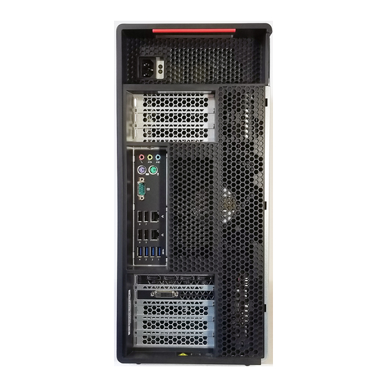
Rear view Some connectors on the rear of your computer are color-coded to help you determine where to connect the cables on your computer. Figure 2. Rear connectors Power cord connector Audio line-out connector Microphone connector PS/2 keyboard connector Serial connector USB 2.0 connectors (4) USB 3.0 connectors (4) PCI card area (PCI cards available vary by computer... - Page 36 DisplayPort connector Attach a high-performance monitor, a direct-drive monitor, or other compatible devices to the DisplayPort connector. DVI monitor connector Attach a DVI monitor or other compatible devices to the DVI monitor connector. Mini DisplayPort connector Attach a high-performance monitor, a direct-drive monitor, or other compatible devices to the Mini DisplayPort connector.
- Page 37 Security-lock slot Attach a Kensington-style cable lock to the security-lock slot to secure your computer. For more information, see “Attaching a Kensington-style cable lock” on page 61. Key-nest slots Install the key holder that comes with the computer cover lock key to the key-nest slots. Ethernet connectors (2) Attach an Ethernet cable for a local area network (LAN).
-
Page 38: Computer Components
Computer components Notes: • Depending on the model, your computer might look slightly different from the illustration. • To remove the computer cover, see “Preparing your computer and removing the computer cover” on page 101. Figure 3. Component locations Power supply assembly Flex adapter (some models) M.2 solid-state drive (some models) Memory modules (amount varies by model) - Page 39 Chapter 2 Product overview...
- Page 40 Figure 4. Major FRUs and CRUs The following table lists the major FRUs shown in Figure 4 “Major FRUs and CRUs” on page 33 and identifies which FRUs are also self-service CRUs or optional-service CRUs. Notes: • Self-service CRUs: Parts to be installed or replaced by customer themselves. •...
-
Page 41: Parts On The System Board
Number FRU description Self-service CRU Optional-service CRU System board Lenovo factory recovery USB key Miscellaneous parts kits Power cord Lenovo recovery disc set Keyboard Mouse For detailed FRU information, such as the FRU part numbers and supported computer models, go to: http://www.lenovo.com/serviceparts-lookup... - Page 42 Memory slot Memory slot Memory slot Flex adapter slot 2 4-pin power connector Optical-drive fan connector 4-pin power connector Front fan assembly connector Thermal sensor Battery Microprocessor 1 Microprocessor fan connector 1 Thermal sensor Memory slot Memory slot Memory slot Memory slot Flex adapter slot 1 4-pin power connector...
-
Page 43: Internal Drives
Internal drives Internal drives are devices that your computer uses to read and store data. You can add drives to your computer to increase storage capacity and enable your computer to read other types of media. Internal drives are installed in bays. When you install or replace an internal drive, note the type and size of the drive that each bay supports and correctly connect the required cables. - Page 44 • Optical drive • Flex module Note: The flex module might be installed with the following: – IEEE 1394 connector – eSATA connector – 29-in-1 card reader – Slim optical drive – Front Thunderbolt adapter kit • Flex bay storage enclosure •...
-
Page 45: Machine Type And Model Label
Machine type and model label The machine type and model label identifies your computer. When you contact Lenovo for help, the machine type and model information helps support technicians to identify your computer and provide faster service. Figure 7. Machine type and model label Computer features For your specific computer model, some features might vary or not apply. - Page 46 – For Windows 7: Click the Start button to open the Start menu. Right-click Computer, and then click Properties. – For Windows 10: Right-click the Start button to open the Start context menu. 2. Click Device Manager. 3. Locate and double-click your device in Device Manager to view device properties. Type the administrator password or provide confirmation if prompted.
- Page 47 Input/Output (I/O) features • 100/1000 Mbps Ethernet connector • 9-pin serial connectors • Audio connectors (audio line-in connector, audio line-out connector, headset connector, and microphone connector) • Display connectors (DisplayPort connector, DVI connector, and Mini DisplayPort connector) (vary by graphics card) •...
- Page 48 Your computer is preinstalled with Windows 7 or Windows 10 operating system. Additional operating systems might be identified by Lenovo as compatible with your computer. To determine if an operating system has been certified or tested for compatibility, check the Web site of the operating system provider.
-
Page 49: Computer Specifications
Accessing a program on your computer Note: For Windows 7, depending on your computer model, some of the Lenovo programs might be ready to be installed, so you must install them manually. Then, you can access and use these programs. -
Page 50: Installing A Program That Is Ready To Be Installed (Windows 7 Only)
An introduction to Lenovo programs This section provides information about the major Lenovo programs available on your operating system. Note: Depending on your computer model, some of the following programs might not be available. - Page 51 Category, click Hardware and Sound ➙ Devices and Printers, and then double-click the device with your computer name. Lenovo ID The Lenovo ID program enables you to create and manage your Lenovo ID. With a Lenovo ID, you can connect to everything Lenovo through a single (Windows 10) account.
- Page 52 P910 Hardware Maintenance Manual...
-
Page 53: Chapter 3. Using Your Computer
When you register your computer with Lenovo, you enter required information into a Lenovo database. The information enables Lenovo to contact you when there is a recall or other severe problem and provide quicker service when you call Lenovo for help. In addition, some locations offer extended privileges and services to registered users. -
Page 54: Handling And Storing A Disc
Handling and storing a disc When handling and storing a disc, follow these guidelines: • Hold the disc by its edges. Do not touch the surface of the side that is not labeled. • To remove dust or fingerprints, wipe the disc with a clean, soft cloth from the center to the outside. Wiping the disc in a circular direction might cause loss of data. -
Page 55: Connecting To A Network
® • Burn a disc using Windows Media Player. 1. Insert a recordable disc into the optical drive that supports recording. 2. Open Windows Media Player. See “Accessing a program on your computer” on page 43. 3. Follow the instructions on the screen. •... -
Page 56: Connecting To A Bluetooth-Enabled Device
Connecting to a Bluetooth-enabled device Bluetooth is a short-range wireless communications technology. Use Bluetooth to establish a wireless connection between your computer and another Bluetooth-enabled device within a distance of about 10 m (32.8 ft). Note: The Bluetooth feature is available only on some models. To connect to a Bluetooth-enabled device, do the following: 1. -
Page 57: Chapter 4. You And Your Computer
1. Comfort Although no single working position is ideal for everyone, here are a few guidelines to help you find a position that suits you best. The following figure sets an example for your reference. © Copyright Lenovo 2016, 2017... -
Page 58: Accessibility Information
Accessibility information Lenovo is committed to providing users who have hearing, vision, and mobility limitations with greater access to information and technology. This section provides information about the ways these users can get the most out of their computer experience. You also can get the most up-to-date accessibility information from the following Web site: http://www.lenovo.com/accessibility... - Page 59 Ease of Access Center Ease of Access Center on the Windows operating system enables users to configure their computers to suit their physical and cognitive needs. To use Ease of Access Center, do the following: 1. Click the Start button to open the Start menu. 2.
- Page 60 4. Follow the instructions on the screen. Screen-reader technologies Screen-reader technologies are primarily focused on software program interfaces, help information systems, and various online documents. For additional information about screen readers, see the following: • Using PDFs with screen readers: http://www.adobe.com/accessibility.html?promoid=DJGVE •...
-
Page 61: Cleaning Your Computer
Then, you can type a message on your computer and send it to the telephone. Documentation in accessible formats Lenovo provides electronic documentation in accessible formats, such as properly tagged PDF files or HyperText Markup Language (HTML) files. Lenovo electronic documentation is developed to ensure that visually impaired users can read the documentation through a screen reader. -
Page 62: Good Maintenance Practices
The cause of a problem might be change in hardware, change in software, or any other actions that might have taken place. A log book can help you or a Lenovo technician determines the cause of a problem. • Create Product Recovery discs. See “Recovery information” on page 89 for more information about using Product Recovery discs to restore the hard disk drive to the factory-default settings. -
Page 63: Moving Your Computer
If the local electrical outlet style is different from the type you are currently using, contact the Lenovo Customer Support Center to purchase either an electrical plug adapter or a new power cord. For a list of Lenovo Support phone numbers, go to http://www.lenovo.com/support/phone. If you cannot find the support telephone number for your country or region, contact your Lenovo reseller. - Page 64 P910 Hardware Maintenance Manual...
-
Page 65: Chapter 5. Security
The keys for the key lock are attached to the rear of the machine. For security, store the keys in a secure place when you are not using them. © Copyright Lenovo 2016, 2017... - Page 66 Note: The key lock and keys are available only on some models. Figure 8. Locking the computer cover P910 Hardware Maintenance Manual...
-
Page 67: Attaching A Kensington-Style Cable Lock
The cable lock also locks the buttons used to open the computer cover. This is the same type of lock used with many notebook computers. You can order such a cable lock directly from Lenovo by searching for Kensington at: http://www.lenovo.com/support Figure 9. -
Page 68: Using Passwords And Windows Accounts
• For Windows 7: Use the Fingerprint Manager Pro or ThinkVantage Fingerprint Software program provided by Lenovo. To open the program, see “Accessing a program on your computer” on page 43. For more information about using the program, refer to the help system of the program. -
Page 69: Using Firewalls
Your computer is preinstalled with an antivirus program to help you guard against, detect, and eliminate viruses. Lenovo provides a full version of antivirus software on your computer with a free 30-day subscription. After 30 days, you must renew the license to continue receiving the antivirus software updates. -
Page 70: Trusted Platform Module (Tpm)
Trusted Platform Module (TPM) TPM is a secure cryptoprocessor that stores cryptographic keys, which in turn protects information stored in your computer. P910 Hardware Maintenance Manual... -
Page 71: Chapter 6. Advanced Configuration
Changing the display language of the Setup Utility program The Setup Utility program supports three display languages: English, French, and simplified Chinese. To change the display language of the Setup Utility program, do the following: © Copyright Lenovo 2016, 2017... -
Page 72: Enabling Or Disabling A Device
Note: For some keyboards, you might need to press Fn+F10 to exit the Setup Utility program. Enabling or disabling the ErP LPS compliance mode Lenovo computers meet the eco-design requirements of the ErP Lot 3 regulation. For more information, go http://www.lenovo.com/ecodeclaration You can enable the ErP LPS compliance mode in the Setup Utility program to reduce the consumption of electricity when your computer is off or in sleep mode. -
Page 73: Enabling Or Disabling The Configuration Change Detection
Note: For some keyboards, you might need to press Fn+F10 to exit the Setup Utility program. When the ErP LPS compliance mode is enabled, you can wake up your computer by doing one of the following: • Press the power button. •... -
Page 74: Using Bios Passwords
4. Select Yes in the window displayed and press Enter to confirm your selection. 5. To save setting and exit the Setup Utility program, press F10, select Yes in the window displayed, and press Enter. Note: For some keyboards, you might need to press Fn+F10 to exit the Setup Utility program. Using BIOS passwords By using the Setup Utility program, you can set passwords to prevent unauthorized access to your computer and data. -
Page 75: Selecting A Startup Device
• Be significantly different from your previous passwords Setting, changing, and deleting a password To set, change, or delete a password, do the following: 1. Start the Setup Utility program. See “Starting the Setup Utility program” on page 65. 2. Select Security. 3. -
Page 76: Exiting The Setup Utility Program
• If the storage device is an external device other than a disc, connect the storage device to the computer. 2. Start the Setup Utility program. See “Starting the Setup Utility program” on page 65. 3. Select Startup. 4. Follow the instructions on the right side of the screen to change the startup device sequence. 5. -
Page 77: Updating The Bios
Start the Setup Utility and view the BIOS Revision level on the Main page. • Sources for obtaining the latest level BIOS available – Lenovo support Web site: http://www.lenovo.com/support/ – Lenovo Customer Support Center – Levels 1 and 2 Support To update the BIOS, see “Updating and recovering the BIOS”... -
Page 78: Configuring Raid
Configuring RAID This chapter provides instructions on how to install hard disk drives and configure Redundant Array of Independent Disks (RAID) for your computer. Depending on your computer model, RAID can be enabled by Intel Rapid Storage Technology enterprise (RSTe) or the AVAGO MegaRAID BIOS. Note: The RAID configuration information described in this chapter is only applicable in the Windows ®... - Page 79 This section provides information about the following topics: • “Entering the Intel RSTe configuration utility” on page 73 • “Creating RAID volumes using the Intel RSTe configuration utility” on page 73 • “Deleting RAID volumes using the Intel RSTe configuration utility” on page 74 •...
-
Page 80: Quick Raid Setup Using The Avago Megaraid Bios Configuration Utility
• The following steps in this section are intended to guide you through a quick setup of basic RAID functions with the AVAGO MegaRAID SAS adapter. For advanced setup and configuration using this adapter, refer to the complete MegaRAID SAS Software User Guide that is available at http://support.lenovo.com/en_US/guides-and-manuals/detail.page?DocID=UM007543. This section provides information about the following topics: •... - Page 81 • RAID Level 0 - Striped disk array – A RAID Level 0 hard disk drive group consisting of at least one hard disk drive – Supported strip size: 8 KB to 1 MB – Better performance without fault tolerance •...
- Page 82 1. Click Configuration Wizard on the WebBIOS main screen to enter the Choosing the Configuration Type window. 2. Press the up and down arrow keys to select one of the three configuration types: • Clear Configuration: Clear the existing configuration. •...
- Page 83 2. Click the hard disk drive you want to set as the hot spare hard disk drive. The Drive window is displayed. 3. Select Make Global HSP or Make Dedicated HSP, and then click Go. 4. The main screen of the AVAGO MegaRAID BIOS configuration utility is displayed, and the hard disk drive you selected is listed as a hot spare hard disk drive in the right pane.
- Page 84 P910 Hardware Maintenance Manual...
-
Page 85: Chapter 7. Troubleshooting, Diagnostics, And Recovery
5. Recover your operating system. Refer to “Recovery information” on page 89. 6. If none of these actions solve your problem, contact the Lenovo Customer Support Center. For a list of Lenovo Support phone numbers, go to http://www.lenovo.com/support/phone. For more information about help, service, and technical assistance, refer to Chapter 10 “Getting information, help, and... -
Page 86: Audio Problems
• The power cord is correctly connected to the rear of the computer and to a working electrical outlet. • If your computer has a secondary power switch on the rear of the computer, ensure that it is switched on. •... -
Page 87: Cd Or Dvd Problems
– For Windows 7: Click the volume icon in the Windows notification area on the taskbar. Then, click the speaker icon on top of the volume control. – For Windows 10: Right-click the volume icon in the Windows notification area on the taskbar. Then, click Open Volume Mixer and select the desired speaker. -
Page 88: Intermittent Problems
• Ensure that the disc surface is clean and not scratched. • Check all cable connections to and from the speakers. • Use the DVD menu for the video to select a different audio track. The playback is slow or choppy. Solutions: •... -
Page 89: Ethernet Lan Problems
Ethernet LAN problems The computer cannot connect to an Ethernet LAN. Solutions: • Connect the cable from the Ethernet connector to the RJ45 connector of the hub. • Enable the Ethernet LAN feature in the Setup Utility program. Refer to “Using the Setup Utility program” on page 65. -
Page 90: Bluetooth Problems
The wireless LAN feature does not work. Solutions: • Enable the wireless LAN feature in the Setup Utility program. Refer to “Using the Setup Utility program” on page 65. • For Windows 10, enable the wireless LAN feature in Windows Settings. Click the Start button to open the Start menu, and then click Settings ➙... -
Page 91: Performance Problems
No sound comes from the Bluetooth headset or headphones. Solution: Set the Bluetooth headset or headphones as the default device. 1. Exit the application that uses the sound device (for example, Windows Media Player). 2. Right-click the volume icon in the Windows notification area on the taskbar. Note: If the volume icon is not displayed in the Windows notification area, add the icon to the notification area. -
Page 92: Serial Connector Problem
• Right-click a blank area on the taskbar and open Task Manager. Then, end some tasks you are not performing. • Install additional memory modules. Refer to Chapter 9 “Installing or replacing hardware” on page 101. To purchase memory modules, go to: http://www.lenovo.com Serial connector problem The serial connector cannot be accessed. Solutions: •... -
Page 93: Software And Driver Problems
Your computer comes with the following diagnostic programs that you can use to help you identify hardware problems. Lenovo Solution Center Lenovo Solution Center enables you to troubleshoot and resolve computer problems. It combines diagnostic tests, system information collection, security status, and support information, along with hints and tips for maximum system performance. -
Page 94: Hardware Diagnostics
For more information about using Lenovo Solution Center and ThinkStation Diagnostics, refer to the help system of the program. If you are unable to isolate and repair the problem yourself after running Lenovo Solution Center or ThinkStation Diagnostics, save and print the log files created by the program. You might need the log files when you speak to a Lenovo technical support representative. -
Page 95: Uefi Diagnostic Program
The hardware diagnostic function is enabled on your computer by default. To disable the function, do the following: 1. Start the Setup Utility program. Refer to “Starting the Setup Utility program” on page 65. 2. From the Setup Utility program main menu, select Advanced ➙ Diagnostics, and then press Enter. 3. -
Page 96: Recovery Information For Windows 10
70. 2. Follow the instructions on the screen to choose the appropriate recovery solution. • Use the recovery disc set provided by Lenovo to restore the entire storage drive to the factory-default settings. – If your computer comes with the recovery disc set, follow the instructions shipped with the disc set. - Page 97 Note: To create a recovery medium, refer to “Good maintenance practices” on page 56. • Use the recovery USB key provided by Lenovo to restore the entire storage drive to the factory-default settings. – If your computer comes with the recovery USB key, follow the instructions shipped with the USB key.
- Page 98 P910 Hardware Maintenance Manual...
-
Page 99: Chapter 8. Service Checkout And Symptom-To-Fru Index
If possible, have this information available when requesting assistance from Service Support and Engineering functions. • Machine type and model • Processor or hard disk drive upgrades • Failure symptom – Do diagnostics indicate a failure? © Copyright Lenovo 2016, 2017... -
Page 100: Symptom-To-Fru Index
– What, when, where, single, or multiple systems? – Is the failure repeatable? – Has this configuration ever worked? – If it has been working, what changes were made prior to its failing? – Is this the original reported failure? •... -
Page 101: Power Supply Problems
Error FRU/Action The start-up drive is not in the boot sequence in Check the configuration and ensure the start-up drive is configuration. in the boot sequence. No operating system installed on the boot drive. Install an operating system on the boot drive. The boot sector on the startup drive is corrupted. -
Page 102: Post Error Codes
Beep symptom FRU/Action 4 long beeps: insufficient shadow RAM resources See the detailed failure information in “POST error codes” for option ROM (error code: 8998) or PCIe/PCI MMIO on page 96. (memory mapped input/output) resources (error code: 8999) 2 long and 3 short beeps: graphic card error Perform the following actions in order: 1. -
Page 103: Miscellaneous Error Conditions
Error code POST error message Description/Action 1820 This error message is displayed when More than one external fingerprint reader is attached. Power off and more than one external fingerprint remove all but the reader that you set reader is connected to the computer. up within your main operating system. - Page 104 Message/Symptom FRU/Action ® Computer will not perform a Wake On LAN (if applicable) 1. Check power supply and signal cable connections to network adapter. 2. Ensure that the operating system settings are set to enable Wake on LAN. 3. Ensure Wake On LAN feature is enabled in Setup/Configuration (see Starting the Setup Utility program) 4.
-
Page 105: Undetermined Problems
Message/Symptom FRU/Action Program loads from the hard disk with a known-good 1. Run the Setup Utility program and check Startup diagnostics diskette in the first 3.5-inch diskette drive sequence. 2. Diskette Drive 3. Diskette Drive Cable 4. System Board 5. Power Supply RPL computer cannot access programs from its own hard 1. - Page 106 P910 Hardware Maintenance Manual...
-
Page 107: Chapter 9. Installing Or Replacing Hardware
1. Remove any media from the drives and turn off all connected devices and the computer. Then, disconnect all power cords from electrical outlets and disconnect all cables that are connected to the computer. 2. Unlock any locking device that secures the computer cover. See “Locking your computer” on page 59. © Copyright Lenovo 2016, 2017... -
Page 108: Installing Or Replacing Hardware
• When installing or replacing an option, use the appropriate instructions in this section along with the instructions that come with the option. • In most areas of the world, Lenovo requires the return of the defective CRU. Information about this will come with the CRU or will come a few days after the CRU arrives. -
Page 109: Cover Presence Switch (Intrusion Switch)
required connector. Then, use the instructions that come with the option to help you make the connection and install any required software or device drivers. Cover presence switch (intrusion switch) Attention: Do not open your computer or attempt any repair before reading and understanding the Chapter 1 “Read this first: Important safety information”... - Page 110 6. Pivot the clip on the bracket outward, and then disengage the failing cover presence switch from the circle clip to remove it from the bracket. Figure 12. Removing the cover presence switch from the bracket 7. Insert the end of the new cover presence switch with the post into the circle clip .
-
Page 111: Direct Cooling Air Baffle
8. Route the cable of the new cover presence switch, and align the notch on the cover presence switch with the tab in the chassis. Then pivot the cover presence switch bracket to the right as shown until it snaps into position. Figure 14. - Page 112 2. Pull the direct cooling air baffle outward by its handle to remove it from the chassis. Figure 15. Removing the direct cooling air baffle P910 Hardware Maintenance Manual...
-
Page 113: Device In An Optical-Drive Bay
To reinstall the direct cooling air baffle, do the following: 1. Align the plastic boards on the top and bottom sides of the direct cooling air baffle with the small gaps in the chassis. Ensure that the handle of the direct cooling air baffle faces towards the front of the chassis. - Page 114 • Optical drive • Flex module Note: The flex module might be installed with the following: – IEEE 1394 connector – eSATA connector – 29-in-1 card reader – Slim optical drive – Front Thunderbolt adapter kit • Fex bay storage enclosure •...
-
Page 115: Storage Drive In The Front-Access Storage Enclosure
4. Press the clip underneath the plastic cover of the optical-drive bay so that the cover is ejected out of the bay. Then, remove the metal shield in the bay. 5. Note the orientation of the new optical drive. Then, slide the optical drive into the optical-drive bay from the front of the chassis until it snaps into position. - Page 116 1. Before removing an old 3.5-inch storage drive, safely eject the old storage drive from the operating system first. For more information, see the Windows help system. 2. Unlock the enclosure cover with the provided key as shown. Press the notch to open the enclosure cover.
- Page 117 5. To install a new 3.5-inch storage drive, flex both sides of the bracket and align pins on the bracket with the corresponding holes in the new drive. Notes: • Ensure that the circuit board faces downward and the connectors face toward the rear of the bracket. •...
- Page 118 2. Unlock the enclosure cover with the provided key as shown. Press the notch to open the enclosure cover. Figure 24. Opening the front-access storage enclosure cover 3. Press the pit on the bracket cover, and then grasp the tilted cover to pull the bracket out of the front-access storage enclosure.
- Page 119 b. Lift the tab of the metal bracket and push the metal bracket with force as shown. Then slide the bracket and remove it from the plastic frame. Figure 27. Removing the metal bracket from the plastic frame of the converter c.
- Page 120 a. Carefully flex both sides of the metal bracket and align the four tabs on the metal bracket with the corresponding holes in the new storage drive. Note: Ensure that the connectors of the storage drive face toward the tab of the metal bracket. Figure 29.
- Page 121 c. Push the metal bracket down until the tab is slightly curved. Then, push the bracket with the storage drive forward as shown until the tab snaps into position. Figure 31. Installing the metal bracket into the plastic frame of the converter d.
-
Page 122: Device In The Multi-Drive Conversion Kit
6. Slide the plastic bracket with the new 2.5-inch storage drive into the front-access storage enclosure until it snaps into position. Press the notch to secure the enclosure cover and lock the enclosure cover with the key. Figure 33. Installing the bracket with the 2.5-inch storage drive into the front-access storage enclosure What to do next: •... - Page 123 a. Press the clip through the hole in the top of the kit as shown and push forward the slim optical drive. Then, slide the slim optical drive out of the kit. Figure 34. Removing the slim optical drive from the kit b.
- Page 124 4. Insert the new slim optical drive into the kit until you hear a click. The slim optical drive is secured in place. Figure 37. Installing the slim optical drive into the kit What to do next: • To work with another piece of hardware, go to the appropriate section. •...
- Page 125 a. Press both clips simultaneously toward each other and slide the 3.5-inch internal storage drive out of the rear of the kit. Figure 39. Removing the 3.5-inch internal storage drive from the rear b. Flex both sides of the bracket to remove the 3.5-inch internal storage drive from the bracket. Do not touch the circuit board on the internal storage drive.
- Page 126 4. Flex the bracket and align pins , and on the bracket with the corresponding holes in the new 3.5-inch internal storage drive. Then install a new 3.5-inch internal storage drive into the bracket. Do not touch the circuit board on the internal storage drive.
- Page 127 6. Pivot the rear cover of the kit inward until you hear a click. The rear cover is secured in place. Figure 43. Pivoting the rear cover inward What to do next: • To work with another piece of hardware, go to the appropriate section. •...
- Page 128 a. Press both clips simultaneously toward each other and slide the 2.5-inch internal storage drive out of the rear of the kit. Figure 45. Removing the 2.5-inch internal storage drive from the rear b. Flex both sides of the bracket to remove the 2.5-inch internal storage drive from the bracket. Figure 46.
- Page 129 4. Flex the bracket and align pins , and on the bracket with the corresponding holes in the new 2.5-inch internal storage drive. Then install a new 2.5-inch internal storage drive into the bracket. Do not touch the circuit board on the internal storage drive.
- Page 130 6. Pivot the rear cover of the kit inward until you hear a click. The rear cover is secured in place. Figure 49. Pivoting the rear cover inward What to do next: • To work with another piece of hardware, go to the appropriate section. •...
- Page 131 3. Pivot the bracket as shown to release tabs , and from the slots. Figure 51. Pivoting the bracket 4. Fold the bracket as shown. Figure 52. Folding the bracket Chapter 9 Installing or replacing hardware...
- Page 132 5. Insert tabs , and into the corresponding slots. Ensure that the tabs are secured in place. Figure 53. Inserting the tabs into the corresponding slots 6. Install a 2.5-inch internal storage drive into the bracket. See “2.5-inch internal storage drive” on page 121.
- Page 133 3. Release tabs , and from the corresponding slots. Figure 55. Releasing tabs , and from the corresponding slots 4. Unfold the bracket as shown. Figure 56. Unfolding the bracket Chapter 9 Installing or replacing hardware...
-
Page 134: Storage Drive In The Flex Bay Storage Enclosure
5. Insert tabs into the corresponding slots. Ensure that the tab is secured in place. Figure 57. Inserting tabs into the corresponding slots 6. Install a 3.5-inch internal storage drive into the bracket. See “3.5-inch internal storage drive” on page 118. What to do next: •... - Page 135 3. If you are replacing a 3.5-inch storage drive, remove the four screws that secure the drive. Then take the old drive out of the flex bay storage enclosure. Note: When installing or removing the storage drive, do not touch the circuit board on the storage drive and make sure that the circuit board faces downward.
- Page 136 4. Install the 3.5-inch storage drive into the flex bay storage enclosure. Then, install the four screws to secure the drive to the flex bay storage enclosure. Figure 59. Installing the 3.5-inch storage drive to the flex bay storage enclosure 5.
- Page 137 1. Prepare your computer. See “Preparing your computer and removing the computer cover” on page 101. 2. If the flex bay storage enclosure is installed in the computer, disconnect the signal cable and the power cable from the 2.5-inch storage drive first. Then, remove the flex bay storage enclosure from the front of the computer.
- Page 138 b. Remove the five screws that secure the 2.5-inch storage drive to the storage converter. Take the drive out of the storage converter. Note: When installing or removing the storage drive, do not touch the circuit board on the storage drive and make sure that the circuit board faces downward.
- Page 139 4. Install the 2.5-inch storage drive into the storage converter. Then, install the five screws to secure the drive to the storage converter. Figure 63. Installing the 2.5-inch storage drive into the storage converter 5. Install the 2.5-inch storage drive and the storage converter into the flex bay storage enclosure. Then, install the four screws to secure the storage converter to the flex bay storage enclosure.
-
Page 140: Device In The 5.25-Inch Flex Module
6. Slide the flex bay storage enclosure into the optical drive bay. See “Device in an optical-drive bay” on page 107. 7. Connect the signal cable and the power cable to the new storage drive. Figure 65. Connecting the cables to the storage drive What to do next: •... - Page 141 3. Lift the clip on the rear of the flex module. Then, slide the flex module cover to the rear of the flex module to remove the cover. Figure 66. Removing the flex module cover 4. Depending on whether you are installing or replacing a slim optical drive, do one of the following: •...
- Page 142 a. Press the button as shown to remove the slim optical drive from the flex module. Figure 68. Removing the slim optical drive from the flex module b. Remove the two screws that secure the clip to remove the plastic clip from the rear of the slim optical drive.
-
Page 143: Card Reader
6. Slide the new slim optical drive with the plastic clip into the flex module until the slim optical drive snaps into position. Figure 71. Installing the slim optical drive in the flex module 7. Position the flex module cover on the flex module. Ensure that the rail guides on the bottom of the flex module cover engage the rails on the flex module. - Page 144 4. Lift the clip on the side of the flex module upward. Then, slide the flex module cover to the rear of the flex module to remove the cover. Figure 73. Removing the flex module cover 5. If you are replacing a card reader, do the following: a.
- Page 145 6. To install a new card reader into the card reader retaining bracket, align the four holes in the card reader with the corresponding studs on the bracket. Then, press the new card reader downward until it snaps into position. Figure 76.
- Page 146 8. Position the flex module cover on the flex module. Ensure that the rail guides on the bottom of the flex module cover engage the rails on the flex module. Then, push the cover to the front of the flex module until it snaps into position.
- Page 147 4. Lift the clip on the side of the flex module upward. Then, slide the flex module cover to the rear of the flex module to remove the cover. Figure 79. Removing the flex module cover 5. If you are replacing an eSATA connector or IEEE 1394 connector, do the following: a.
- Page 148 6. Note the orientation of the eSATA connector or IEEE 1394 connector and route the eSATA connector or IEEE 1394 connector cable into the cable clip. 7. Place the eSATA connector or IEEE 1394 connector into the metal retainer. Then, insert the eSATA connector or IEEE 1394 connector into the corresponding slot in the flex module as shown.
- Page 149 • To complete the installation or replacement, go to “Completing the parts replacement” on page 213. Front Thunderbolt adapter kit The front Thunderbolt adapter kit includes the following parts: • A front Thunderbolt I/O adapter • A front Thunderbolt PCI Express x4 card •...
- Page 150 b. Pull the clip as shown to remove the front Thunderbolt I/O adapter and the retaining bracket out of the flex module. Figure 84. Removing the front Thunderbolt adapter and the retaining bracket out of the flex module c. Flex the four clips on the sides of the retaining bracket to remove the front Thunderbolt I/O adapter from the bracket.
- Page 151 a. Remove the dummy bezel and install the bezel in the front Thunderbolt adapter kit to the flex module first. Figure 86. Installing the bezel to the flex module b. To install a new front Thunderbolt I/O adapter into the retaining bracket, align the four holes in the front Thunderbolt I/O adapter with the corresponding mounting studs on the bracket.
- Page 152 c. Hold the clip on the retaining bracket and then insert the front Thunderbolt I/O adapter and the retaining bracket into the flex module as shown until they snap into position. Figure 88. Installing the front Thunderbolt adapter and the retaining bracket into the flex module 7.
-
Page 153: Internal Storage Drive
9. Route the cables through the two holes in the rear of the flex module. Position the flex module cover on the flex module. Ensure that the rail guides on the bottom of the cover engage the rails on the flex module. - Page 154 • “PCI card” on page 172 (applies to a PCI Express solid-state drive) 3.5-inch storage drive Note: Depending on your computer model, a 3.5-inch hard disk drive or a 3.5-inch hybrid drive might come with your computer. To install or replace a 3.5-inch storage drive in a hard-disk-drive bay, do the following: 1.
- Page 155 • If you are replacing a storage drive, flex the sides of the bracket to release the four pins from the storage drive. Then, remove the storage drive from the bracket. Figure 92. Removing the storage drive from the bracket Chapter 9 Installing or replacing hardware...
- Page 156 5. Hold the storage drive so that the connectors face towards the rear of the bracket and the circuit board faces upward. Then, flex the sides of the bracket and align the four pins on the bracket with the corresponding holes in the storage drive. Note: Do not touch the circuit board of the storage drive.
- Page 157 6. Slide the bracket together with the installed storage drive into the hard-disk-drive bay until the bracket snaps into position. Figure 94. Installing the hard-disk-drive bracket What to do next: • To work with another piece of hardware, go to the appropriate section. •...
- Page 158 • If you are replacing a storage drive, flex the sides of the bracket to release the four pins from the storage drive. Then, remove the storage drive from the bracket. Figure 95. Removing the storage drive from the bracket 5.
- Page 159 6. Install the bracket with the new storage drive into the hard-disk-drive bay. See step 6 on page 151. What to do next: • To work with another piece of hardware, go to the appropriate section. • To complete the installation or replacement, go to “Completing the parts replacement” on page 213. Installing or replacing a 2.5-inch storage drive with a converter in a hard-disk-drive bay Attention: Do not open your computer or attempt any repair before reading and understanding the Chapter 1 “Read this first: Important safety information”...
- Page 160 b. Pivot tab on the metal adapter upward and push the adapter as shown until the four tabs on the adapter are slide into the notches . Then, pivot the adapter as shown to remove it with the storage drive from the converter. Figure 98.
- Page 161 5. Note the orientation of the connector on the new storage drive. Then, flex the sides of the adapter and align the four pins with the corresponding holes in the storage drive. Note: Do not touch the circuit board (if accessible) of the 2.5-inch storage drive. Figure 100.
- Page 162 What to do next: • To work with another piece of hardware, go to the appropriate section. • To complete the installation or replacement, go to “Completing the parts replacement” on page 213. M.2 solid-state drive Attention: Do not open your computer or attempt any repair before reading and understanding the Chapter 1 “Read this first: Important safety information”...
- Page 163 6. The heat sink is secured by a mounting stud. Pinch the tab of the mounting stud and turn the mounting stud 90-degree counterclockwise to release the heat sink. Then, lift the heat sink off the flex adapter. Figure 103. Removing the heat sink from the flex adapter 7.
- Page 164 9. Hold the new M.2 solid-state drive by its edges, ensure that the circuit board side is upward, and then insert the drive into the M.2 slot until it is secured tightly. Then, insert the plug of the retention latch into the hole to secure the new drive.
- Page 165 11. Pinch the tab of the mounting stud and press the mounting stud downward. Then, turn the mounting stud 90-degree clockwise to secure the heat sink to the flex adapter. Figure 107. Securing the heat sink on the flex adapter 12.
-
Page 166: Blind-Connect Assembly
What to do next: • To work with another piece of hardware, go to the appropriate section. • To complete the installation or replacement, go to “Completing the parts replacement” on page 213. Blind-connect assembly Attention: Do not open your computer or attempt any repair before reading and understanding the Chapter 1 “Read this first: Important safety information”... - Page 167 • The cable routing varies depending on whether the blind-connect assembly is installed in the upper drive cage or the lower drive cage. Record the cable routing method before pulling out the cables. When you install the new blind-connect assembly afterwards, route the cables in the same way according to your record.
- Page 168 8. Align the four tabs at the bottom of the storage drive bay with the slots on the new blind-connect board. Then, press down the board and slide it as shown until it snaps into position. Figure 111. Installing the blind-connect assembly 9.
-
Page 169: Front Fan Assembly
Front fan assembly Attention: Do not open your computer or attempt any repair before reading and understanding the Chapter 1 “Read this first: Important safety information” on page 1. CAUTION: Hazardous moving parts. Keep fingers and other body parts away. To replace a front fan assembly, do the following: 1. -
Page 170: Multi-Function Brackets
4. Slide the front fan assembly into the multi-function bracket until it snaps into position. Figure 114. Installing the front fan assembly What to do next: • To work with another piece of hardware, go to the appropriate section. • To complete the installation or replacement, go to “Completing the parts replacement” on page 213. Multi-function brackets Attention: Do not open your computer or attempt any repair before reading and understanding the Chapter 1 “Read this first: Important safety information”... - Page 171 7. Hold the handle and the foot at the same time and pull the bracket to the rear of the chassis to remove the bracket. Figure 115. Removing the multi-function bracket 8. Align the three tabs on the bracket with the corresponding holes in the chassis. Then, insert the three tabs into the corresponding holes until the bracket snaps into position.
-
Page 172: Power Supply Assembly
• To complete the installation or replacement, go to “Completing the parts replacement” on page 213. Power supply assembly Attention: Do not open your computer or attempt any repair before reading and understanding the Chapter 1 “Read this first: Important safety information” on page 1. Although there are no moving parts in your computer after the power cord has been disconnected, the following warnings are required for your safety and proper Underwriters Laboratories (UL) certification. - Page 173 3. Pivot the handle to the left at an angle of about 90 degrees. Then, pull the handle as shown to remove the power supply assembly from the chassis. Figure 117. Removing the power supply assembly 4. With the handle open, slide the power supply assembly into the power supply assembly bay until it snaps into position.
-
Page 174: Battery
Battery Attention: Do not open your computer or attempt any repair before reading and understanding the Chapter 1 “Read this first: Important safety information” on page 1. Your computer has a special type of memory that maintains the date, time, and settings for built-in features, such as parallel-connector assignments (configuration). -
Page 175: Flex Adapter
Note: When the computer is turned on for the first time after replacing the battery, an error message might be displayed. This is normal after replacing the battery. 10. Turn on the computer and all attached devices. 11. Use the Setup Utility program to set the date, time, and any passwords. See “Using the Setup Utility program”... - Page 176 • If your are replacing a failing flex adapter, pivot the tab upward to open the latch inside the multi-function bracket. Then, grasp the failing flex adapter by its edges and gently pull it out of the flex adapter slot. Notes: –...
- Page 177 5. Align the notch on the new flex adapter with the slot key in a flex adapter slot. Then, slide the plastic retainer of the new flex adapter downward into the corresponding slot in the multi-function bracket. Then, insert the adapter into the flex adapter slot until it is secured tightly. Notes: •...
-
Page 178: Pci Card
What to do next: • To work with another piece of hardware, go to the appropriate section. • To complete the installation or replacement, go to “Completing the parts replacement” on page 213. PCI card Attention: Do not open your computer or attempt any repair before reading and understanding the Chapter 1 “Read this first: Important safety information”... - Page 179 a. On the left of the PCI card slot, lift the handle until it stops, and then pivot it to the left until it stops. The PCI card latch is opened. Figure 126. Opening the PCI card latch b. Remove the appropriate metal slot cover on the rear of the chassis. •...
- Page 180 b. Grasp the PCI card retainer by its edges and gently pull it out of the latch. Remove the retainer completely from the PCI card latch. Figure 128. Removing the PCI card retainer P910 Hardware Maintenance Manual...
- Page 181 c. On the left of the PCI card slot, lift the handle until it stops, and then pivot it to the left until it stops. The PCI card latch is opened. Figure 129. Opening the PCI card latch Chapter 9 Installing or replacing hardware...
- Page 182 d. Grasp the card that is currently installed and gently pull it out of the slot. Notes: – If the card is connected to other device, disconnect the cables from the card. – If the card is held in place by a retaining latch, press the card retaining latch as shown to disengage the latch.
- Page 183 6. To install a new PCI card, align the notch on the new PCI card with the slot key in the PCI card slot. Then, insert the new PCI card downward into the card slot until it is secured tightly. See “Parts on the system board”...
- Page 184 7. Pivot the handle to the right until it stops, and then press it downward until the latch snaps into position. Figure 133. Closing the PCI card latch P910 Hardware Maintenance Manual...
- Page 185 8. Insert the corresponding end of the PCI card retainer into the gaps in the PCI card latch as shown. Pivot the retainer downward to insert part into the corresponding slot in the front fan assembly. Figure 134. Installing the PCI card retainer 9.
-
Page 186: Full-Length Pci Express Card
Full-length PCI Express card Attention: Do not open your computer or attempt any repair before reading and understanding the Chapter 1 “Read this first: Important safety information” on page 1. Your computer has the following PCI card slots: • PCI Express x1 card slot •... - Page 187 a. On the right of the PCI card slot, pivot the tab outward until it stops. The card latch opened. On the left of the PCI card slot, lift the handle until it stops, and then pivot it to the left until it stops.
- Page 188 a. On the right of the PCI card slot, pivot the tab outward until it stops. The card latch opened. On the left of the PCI card slot, lift the handle until it stops, and then pivot it to the left until it stops.
- Page 189 – The card fits tightly into the card slot. If necessary, alternate moving each side of the card a small amount until it is removed from the card slot. Figure 140. Removing the full-length PCI Express card Chapter 9 Installing or replacing hardware...
- Page 190 6. To install a new full-length PCI Express card, align the notch on the new full-length PCI Express card with the slot key in the PCI card slot. Then, insert the new card downward into the card slot until it is secured tightly.
-
Page 191: Super Capacitor Module
7. Pivot the handle to the right until it stops, and then press it downward until the latch snaps into position. Pivot the tab inward until it snaps into position. Figure 142. Closing PCI card latches 8. Connect the power cable of the full-length PCI Express card to the new card. See “Parts on the system board”... - Page 192 4. If necessary, remove the direct cooling air baffle for easier operation. See “Direct cooling air baffle” on page 105. 5. Depending on whether you are installing or replacing the super capacitor module, do one of the following: • If you are installing the super capacitor module, go to step 7. •...
- Page 193 7. Gently pivot the plastic retaining clip on the bracket as shown and install the new super capacitor module into the bracket at the same time. Note: Ensure that the cable of the super capacitor module is oriented as shown. Figure 144.
-
Page 194: Memory Module
What to do next: • To work with another piece of hardware, go to the appropriate section. • To complete the installation or replacement, go to “Completing the parts replacement” on page 213. Memory module Attention: Do not open your computer or attempt any repair before reading and understanding the Chapter 1 “Read this first: Important safety information”... - Page 195 • If you are installing a memory module, open the retaining clips of the memory slot into which you want to install the memory module. Figure 147. Opening retaining clips • If you are replacing a memory module, open the retaining clips and gently pull the memory module out of the memory slot.
-
Page 196: Heat Sink And Fan Assemblies
6. To install a new memory module, position the new memory module over the memory slot. Ensure that the notch on the memory module aligns correctly with the slot key on the system board. Push the memory module straight down into the slot until the retaining clips close. Note: Do not touch the circuit board of the memory module. - Page 197 6. Follow this sequence to remove the four screws that secure the heat sink and fan assembly to the system board: a. Partially remove screw , then fully remove screw , and then fully remove screw b. Partially remove screw , then fully remove screw , and then fully remove screw Note: Carefully remove the four screws from the system board to avoid any possible damage to the...
-
Page 198: Rear Fan Assembly
• To complete the installation or replacement, go to “Completing the parts replacement” on page 213. Rear fan assembly Attention: Do not open your computer or attempt any repair before reading and understanding the Chapter 1 “Read this first: Important safety information” on page 1. CAUTION: Hazardous moving parts. -
Page 199: Wi-Fi Units
5. Slide the new rear fan assembly into the rear fan assembly bay until it snaps into position. Figure 152. Installing the rear fan assembly 6. Reinstall the direct cooling air baffle. See “Direct cooling air baffle” on page 105. What to do next: •... - Page 200 2. Unscrew the Wi-Fi antenna connectors to remove the Wi-Fi antenna from the rear of the computer. Figure 153. Removing the Wi-Fi antenna 3. To remove the Wi-Fi adapter card, do the following: a. If your computer comes with a Wi-Fi card module that supports the Bluetooth function, disconnect the Bluetooth cable from the Wi-Fi adapter card.
- Page 201 b. On the rear of the computer, lift the handle and pivot it as shown until it stops. The PCI card latch is opened. Figure 155. Opening the PCI card latch c. Grasp the Wi-Fi adapter card and gently pull it out of the slot. Figure 156.
- Page 202 a. Remove the Wi-Fi adapter card from the computer, and then disconnect the two Wi-Fi antenna cables from the Wi-Fi card module. Figure 157. Disconnecting the Wi-Fi antenna cables b. Remove the two screws that secure the Wi-Fi card module to the Wi-Fi adapter card. Figure 158.
- Page 203 c. Pull the Wi-Fi card module out of the mini PCI Express slot. Figure 159. Removing the Wi-Fi card module What to do next: • To work with another piece of hardware, go to the appropriate section. • To complete the installation or replacement, go to “Completing the parts replacement” on page 213. Installing the Wi-Fi units To install the Wi-Fi units, do the following: 1.
- Page 204 b. Install the two screws to secure the Wi-Fi card module to the Wi-Fi adapter card. Figure 161. Installing the screws to secure the Wi-Fi card module c. Connect the two Wi-Fi antenna cables to the Wi-Fi card module. Figure 162. Connecting the Wi-Fi antenna cables 3.
- Page 205 a. Install the Wi-Fi adapter card into the PCI Express card slot on the system board. See “Parts on the system board” on page 35. Figure 163. Installing the Wi-Fi adapter card b. Pivot the PCI card latch and push it back in until it snaps into position. c.
-
Page 206: Microprocessor
4. Attach the Wi-Fi antenna cable connectors to the corresponding Wi-Fi antenna connectors the rear of the computer as shown. Figure 164. Installing the Wi-Fi antenna 5. Tighten the Wi-Fi antenna cable connectors to secure them to the rear of the computer. What to do next: •... - Page 207 Notes: • Ensure that you install the correct type of microprocessor option your computer supports. When two microprocessors are installed, both must be identical. • For E5-1600 v4 series microprocessors, the computer can support only one installed. If you want to install two microprocessors into your computer, use the E5-2600 v4 series microprocessors.
- Page 208 7. Gently press down the small handle to open the microprocessor retainer. Pivot the retainer upward until it is in the fully open position. Figure 166. Opening the microprocessor retainer 8. Lift the microprocessor straight up and out of the microprocessor socket. Place the old microprocessor on a static-protective surface.
- Page 209 10. Remove the new microprocessor from the protective cover that protects the gold contacts on the bottom of the new microprocessor. Do not touch the pins on the microprocessor socket or the gold contacts on the bottom of the new microprocessor. Figure 168.
- Page 210 12. Pivot the microprocessor retainer downward to close the retainer. Figure 170. Closing the microprocessor retainer 13. Gently press down the small handle and then push the handle inward to secure it. Then gently press down the small handle and push the handle inward to lock the microprocessor retainer into position. Ensure that the new microprocessor is secured in the socket.
- Page 211 This topic provides instructions on how to install the second microprocessor. Depending on the model, your computer might come with one or two microprocessors. For computer models with one microprocessor, the microprocessor is installed in the microprocessor socket 1 and the microprocessor socket 2 is protected by a plastic socket cover.
- Page 212 5. Open the small handle by gently pressing down the small handle. Then pull the small handle slightly outward to release it from the secured position. Then, open the other small handle by following the same instructions. Ensure that the small handles are in the fully open position. Note: There are two marks on the microprocessor retainer.
- Page 213 8. Remove the new microprocessor from the protective cover that protects the gold contacts on the bottom of the new microprocessor. Do not touch the pins on the microprocessor socket or the gold contacts on the bottom of the new microprocessor. Figure 174.
- Page 214 10. Remove the plastic microprocessor socket cover. Store the microprocessor socket cover in case that you later remove the microprocessor and need the socket cover to protect the pins on the socket. Note: Do not remove the socket cover until you install a microprocessor into the socket. If you remove the microprocessor, install the socket cover or a new microprocessor in the first place.
-
Page 215: System Board
12. Gently press down the small handle and then push the handle inward to secure it. Then gently press down the small handle and push the handle inward to lock the microprocessor retainer into position. Ensure that the new microprocessor is secured in the socket. Note: There are two marks on the microprocessor retainer. - Page 216 4. Remove the multi-function brackets. See “Multi-function brackets” on page 164. 5. Remove the front fan assemblies. See “Front fan assembly” on page 163. 6. Remove the rear fan assemblies. See “Rear fan assembly” on page 192. 7. Remove the power supply assembly. See “Power supply assembly” on page 166. 8.
- Page 217 16. To install the new system board, position the new system board in the chassis. Align the twelve mounting studs on the bottom of the system board with the corresponding holes in the chassis. Then, push the new system board toward the rear of the computer until it snaps into position. Ensure that the system board is secured by the metal retainer.
- Page 218 1. Pivot the microprocessor retainer downward to close the retainer. Figure 181. Closing the microprocessor retainer 2. Gently press down the small handle , and then push the handle inward to secure it. Then gently press down the small handle and push the handle inward to lock the microprocessor retainer into position.
-
Page 219: Completing The Parts Replacement
What to do next: • To work with another piece of hardware, go to the appropriate section. • To complete the installation or replacement, go to “Completing the parts replacement” on page 213. Completing the parts replacement After completing the installation or replacement for all parts, reinstall the computer cover and reconnect cables. - Page 220 6. Reconnect the external cables and power cords to the corresponding connectors on the computer. See “Hardware locations” on page 27. 7. Update the configuration of your computer if necessary. See “Using the Setup Utility program” on page 65. 8. If a newly installed hardware component does not work normally, update the device driver. See “Keeping your computer current”...
-
Page 221: Chapter 10. Getting Information, Help, And Service
User Guide. Lenovo Web site The Lenovo Web site (http://www.lenovo.com) provides up-to-date information and services to help you buy, upgrade, and maintain your computer. You also can do the following: • Shop for desktop and notebook computers, monitors, projectors, upgrades, and accessories for your computer, and special offers. -
Page 222: Lenovo Support Web Site
• Engineering Change management - There might be changes that are required after a product has been sold. Lenovo or your reseller will make selected Engineering Changes (ECs) that apply to your hardware available. -
Page 223: Using Other Services
For technical assistance with the installation of or questions related to Service Packs for your preinstalled Microsoft Windows product, go to the Microsoft Product Support Web site at http://support.microsoft.com. You also can contact the Lenovo Customer Support Center for help. Some fees might apply. Purchasing additional services During and after the warranty period, you can purchase additional services. - Page 224 P910 Hardware Maintenance Manual...
-
Page 225: Appendix A. System Memory Speed
E5-2623 v4, E5-2620 v4, E5-2630L 2133 MHz v4, E5-2628L v4, E5-2618L v4 1.2 V Intel Xeon E5-2609 v4, E5-2603 v4, 1866 MHz E5 2608L v4, E5-2620 v3 1.2 V Intel Xeon E5-2609 v3 1600 MHz © Copyright Lenovo 2016, 2017... - Page 226 P910 Hardware Maintenance Manual...
-
Page 227: Appendix B. Supplemental Information About The Ubuntu Operating System
The LLW also is preinstalled on the computer. To access the LLW, go to the following directory: /usr/share/doc/lenovo-doc If you cannot view the LLW either from the Web site or from your computer, contact your local Lenovo office or reseller to obtain a printed version of the LLW. - Page 228 P910 Hardware Maintenance Manual...
-
Page 229: Appendix C. Regulatory Information
• Consult an authorized dealer or service representative for help. Lenovo is not responsible for any radio or television interference caused by using other than specified or recommended cables and connectors or by unauthorized changes or modifications to this equipment. - Page 230 Geräte der Klasse B. Dieses Gerät ist berechtigt, in Übereinstimmung mit dem Deutschen EMVG das EG-Konformitätszeichen - CE - zu führen. Verantwortlich für die Konformitätserklärung nach Paragraf 5 des EMVG ist die Lenovo (Deutschland) GmbH, Meitnerstr. 9, D-70563 Stuttgart. P910 Hardware Maintenance Manual...
-
Page 231: Eurasian Compliance Mark
The ac power cord shipped with your product can be used only for this specific product. Do not use the ac power cord for other devices. Lenovo product service information for Taiwan Keyboard and mouse compliance statement for Taiwan Eurasian compliance mark Brazil audio notice Ouvir sons com mais de 85 decibéis por longos períodos pode provocar danos ao sistema auditivo. -
Page 232: Additional Regulatory Information
All regulatory notices are available on the Lenovo Support Web site in electronic format. To access electronic copies of the documentation, go to http://www.lenovo.com/support. -
Page 233: Appendix D. Weee And Recycling Information
Collecting and recycling a disused Lenovo computer or monitor If you are a company employee and need to dispose of a Lenovo computer or monitor that is the property of the company, you must do so in accordance with the Law for Promotion of Effective Utilization of Resources. -
Page 234: Recycling Information For Brazil
If you need to replace it with a new one, contact your place of purchase or contact Lenovo for service. If you need to dispose of a disused lithium battery, insulate it with vinyl tape, contact your place of purchase or an industrial-waste-disposal operator, and follow their instructions. -
Page 235: Battery Recycling Information For The European Union
If the battery needs to be replaced, contact your place of purchase or contact Lenovo for service. If you need to dispose of a lithium battery, insulate it with vinyl tape, contact your place of purchase or a waste-disposal operator, and follow their instructions. - Page 236 P910 Hardware Maintenance Manual...
-
Page 237: Appendix E. Restriction Of Hazardous Substances Directive (Rohs)
For more information about Lenovo worldwide compliance on RoHS, go to: http://www.lenovo.com/social_responsibility/us/en/RoHS_Communication.pdf China RoHS Turkish RoHS The Lenovo product meets the requirements of the Republic of Turkey Directive on the Restriction of the Use of Certain Hazardous Substances in Waste Electrical and Electronic Equipment (WEEE). © Copyright Lenovo 2016, 2017... -
Page 238: Ukraine Rohs
Ukraine RoHS India RoHS RoHS compliant as per E-Waste (Management & Handling) Rules. Taiwan RoHS P910 Hardware Maintenance Manual... -
Page 239: Appendix F. Energy Star Model Information
For more information about ENERGY STAR, go to: http://www.energystar.gov Lenovo encourages you to make efficient use of energy an integral part of your day-to-day operations. To help in this endeavor, set the following power-management features to take effect when your computer has been inactive for a specified duration: Table 4. - Page 240 4. Follow the instructions on the screen. P910 Hardware Maintenance Manual...
-
Page 241: Appendix G. Notices
Lenovo representative for information on the products and services currently available in your area. Any reference to a Lenovo product, program, or service is not intended to state or imply that only that Lenovo product, program, or service may be used. Any functionally equivalent product, program, or service that does not infringe any Lenovo intellectual property right may be used instead. -
Page 242: Trademarks
Trademarks The following terms are trademarks of Lenovo in the United States, other countries, or both: Lenovo The Lenovo logo ThinkStation The ThinkStation logo ThinkVantage Microsoft, Windows, and Windows Media are trademarks of the Microsoft group of companies. Intel, Thunderbolt, and Xeon are trademarks of Intel Corporation or its subsidiaries in the U.S. and/or other countries.
Need help?
Do you have a question about the ThinkStation p910 and is the answer not in the manual?
Questions and answers