Lenovo ThinkStation P320 Tiny User Manual
Customer replaceable unit
Hide thumbs
Also See for ThinkStation P320 Tiny:
- Hardware maintenance manual (174 pages) ,
- User manual (84 pages) ,
- User manual (140 pages)

Subscribe to Our Youtube Channel
Related Manuals for Lenovo ThinkStation P320 Tiny


Summary of Contents for Lenovo ThinkStation P320 Tiny
- Page 1 P320 Tiny Customer Replaceable Unit Guide Machine Types (MTs): 30C1 (Energy Star), 30C2 (Energy Star), and 30C3 (Energy Star)
- Page 2 Important Product Information Guide. Fourth Edition (May 2018) © Copyright Lenovo 2017, 2018. LIMITED AND RESTRICTED RIGHTS NOTICE: If data or software is delivered pursuant to a General Services Administration “GSA” contract, use, reproduction, or disclosure is subject to restrictions set forth in Contract No. GS-...
-
Page 3: Table Of Contents
Handling static-sensitive devices ..Trademarks ....Knowing replaceable parts ..© Copyright Lenovo 2017, 2018... - Page 4 P320 Tiny Customer Replaceable Unit Guide...
-
Page 5: Chapter 1. Product Overview
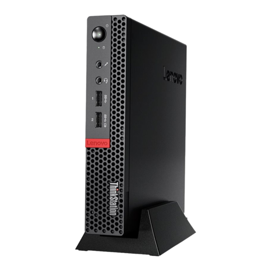
This indicator is on when the computer is powered on. • Microphone connector Used to connect a microphone to your computer. You can use the microphone to record sounds or interact with the computer using speech-recognition software. • Power button © Copyright Lenovo 2017, 2018... -
Page 6: Rear View
Used to turn on your computer. When you cannot shut down the computer from the operating system, press and hold the power button for four or more seconds to turn off the computer. • Power indicator This indicator is on when the computer is on. •... -
Page 7: System Board
Used to connect an Ethernet cable for network access. • Mini DisplayPort connector Used to send or receive audio and video signals. You can attach a compatible audio or video device to this connector, such as a high-performance monitor. Depending on the computer model, the connector might vary. -
Page 8: Machine Type And Model Label
M.2 storage drive slot 1 Machine type and model label The machine type and model label identifies your computer. When you contact Lenovo for help, the machine type and model information helps support technicians to identify your computer and provide faster service. -
Page 9: Chapter 2. I/O Box
• The connectors on the I/O box cannot be enabled or disabled individually. To enable or disable any of the connectors on the I/O box, enable or disable the USB connectors on the rear of the computer. © Copyright Lenovo 2017, 2018... - Page 10 • The I/O box enables you to wake up the computer from standby mode through operations on devices connected to the I/O box connectors. P320 Tiny Customer Replaceable Unit Guide...
-
Page 11: Chapter 3. Connecting To Other Devices
The cable lock also locks the buttons used to open the computer cover. This is the same type of lock used with many notebook computers. You can order such a cable lock directly from Lenovo by searching for Kensington at: https://support.lenovo.com Figure 5. - Page 12 5. Press the mode-switching button on the TIO monitor to change from the TIO mode to the DP mode or HDMI mode. When the computer works with the discrete graphics card, pressing the power button on the TIO monitor only turns on or turns off the TIO monitor. Devices connected to the TIO monitor do not function the same as they are connected to the computer.
-
Page 13: Chapter 4. Features
• External I/O box (optional) • External optical drive box (optional) • Memory slots • M.2 storage drive slots • PCI Express graphics card slot Network features • Ethernet LAN • Wireless LAN (optional) • Bluetooth (optional) © Copyright Lenovo 2017, 2018... - Page 14 Physical dimensions • Width: 35 mm (1.4 inches) • Height: 183 mm (7.2 inches) • Depth: 179 mm (7.1 inches) Weight (without the package) • Maximum configuration as shipped: 1.3 kg (2.9 lb) P320 Tiny Customer Replaceable Unit Guide...
-
Page 15: Chapter 5. Replacing Hardware
• In most areas of the world, Lenovo requires the return of defective CRUs (Customer Replaceable Units). Information about this will come with the CRU or will come a few days after the CRU arrives. - Page 16 These CRUs are isolated parts within the computer. They are usually concealed by an access panel that is secured by more than two screws. You must remove the screws and panel to access the specific CRU. Optional-service CRUs can be removed and installed by users or, during the warranty period, by a Lenovo service technician.
- Page 17 Figure 6. CRUs and FRUs Number FRU description Self-service CRU Optional-service CRU Vertical stand Power adapter bracket Power adapter Power cord Computer cover Microprocessor Chapter 5 Replacing hardware...
-
Page 18: Replacing Crus
CRUs: self-service and optional-service. To check the locations of CRUs, see “Knowing replaceable parts” on page 11. Note: To replace other parts except the CRUs mentioned in the following sections, contact a Lenovo service technician. The support phone numbers are available at https://pcsupport.lenovo.com/supportphonelist... -
Page 19: Replacing The Keyboard Or Wireless Keyboard
Replacing the keyboard or wireless keyboard Note: The wireless keyboard is available only on some models. Replacing the keyboard 1. Turn off the computer and disconnect all power cords from electrical outlets. 2. Disconnect the old keyboard cable from the computer. 3. -
Page 20: Replacing The Mouse Or Wireless Mouse
4. Remove the USB dongle from the keyboard compartment or from the wireless mouse compartment and connect it to an available USB connector on the computer. 5. Close the compartment cover. The keyboard is ready for use. Replacing the mouse or wireless mouse Note: The wireless mouse is available only on some models. - Page 21 Figure 10. Opening the battery compartment b. Take out the USB dongle. Figure 11. Taking out the USB dongle c. Connect the USB dongle to a USB connector. Chapter 5 Replacing hardware...
- Page 22 Figure 12. Connecting the USB dongle to a USB connector d. Install the mouse batteries. Figure 13. Installing the mouse batteries e. Close the battery compartment cover. P320 Tiny Customer Replaceable Unit Guide...
-
Page 23: Replacing The Power Adapter
Figure 14. Closing the battery compartment cover f. Push the power switch to the on position. Figure 15. Pushing the power switch to the on position Notes: • The green LED indicates that the mouse is ready for use. • The flashing amber LED indicates a low battery level. •... - Page 24 Note: The P320 Tiny computer supports the following Tiny-in-one (TIO) monitor models: Tiny-in-One 23- Monitor (MT: 10DQ), Tiny-in-One 22- Monitor (MT: 10LK), Tiny-in-One 24- Monitor (MT: 10LL), TIO22Gen3- Monitor (MT: 10R1), TIO22Gen3Touch- Monitor (MT: 10R0), TIO24Gen3- Monitor (MT: 10QY), and TIO24Gen3Touch- Monitor (MT: 10QX).
- Page 25 Figure 17. Removing the power cord c. Install the power cord. Figure 18. Installing the power cord d. Install the power adapter. Chapter 5 Replacing hardware...
-
Page 26: Replacing The Vertical Stand
Figure 19. Installing the power adapter Replacing the vertical stand Attention: Do not open your computer or attempt any repairs before reading the Important Product Information Guide. 1. Remove any media from the drives and turn off all connected devices and the computer. 2. -
Page 27: Replacing The Vesa Mount Bracket
Figure 21. Installing the vertical stand Replacing the VESA mount bracket Attention: Do not open your computer or attempt any repairs before reading the Important Product Information Guide. 1. Remove any media from the drives and turn off all connected devices and the computer. 2. -
Page 28: Replacing The External Optical Drive
b. Install the VESA mount bracket. Figure 23. Installing the VESA mount bracket Replacing the external optical drive Attention: Do not open your computer or attempt any repairs before reading the Important Product Information Guide. 1. Remove any media from the drives and turn off all connected devices and the computer. 2. - Page 29 Figure 24. Removing the external optical drive box b. Remove the external optical drive. Figure 25. Removing the external optical drive c. Install the external optical drive. Chapter 5 Replacing hardware...
-
Page 30: Replacing The External I/O Box
Figure 26. Installing the external optical drive d. Install the external optical drive box. Figure 27. Installing the external optical drive box Replacing the external I/O box Attention: Do not open your computer or attempt any repairs before reading the Important Product Information Guide. - Page 31 1. Remove any media from the drives and turn off all connected devices and the computer. 2. Disconnect all power cords from electrical outlets and disconnect all cables that are connected to the computer and the external I/O box. 3. Replace the external I/O box. a.
-
Page 32: Replacing The Power Adapter Bracket
Replacing the power adapter bracket Attention: Do not open your computer or attempt any repairs before reading the Important Product Information Guide. 1. Remove any media from the drives and turn off all connected devices and the computer. 2. Disconnect all power cords from electrical outlets and disconnect all cables that are connected to the computer. -
Page 33: Removing The Computer Cover
Removing the computer cover Attention: Do not open your computer or attempt any repairs before reading the Important Product Information Guide. 1. Remove any media from the drives and turn off all connected devices and the computer. 2. Disconnect all power cords from electrical outlets and disconnect all cables that are connected to the computer. - Page 34 Figure 33. Removing the storage drive b. Remove the storage drive bracket. Figure 34. Removing the storage drive bracket c. Install the storage drive bracket. P320 Tiny Customer Replaceable Unit Guide...
-
Page 35: Replacing The Internal Speaker
Figure 35. Installing the storage drive bracket d. Install the storage drive. Figure 36. Installing the storage drive 6. Connect the storage drive cables to the system board. See “System board” on page 3. 7. Reinstall the computer cover and reconnect the cables. For details, see “Completing the parts replacement”... - Page 36 3. Remove the computer cover. For details, see “Removing the computer cover” on page 29. 4. Disconnect the internal speaker cable from the internal speaker connector on the system board. See “System board” on page 3. 5. Replace the internal speaker. a.
-
Page 37: Replacing The Bottom Cover
Replacing the bottom cover Attention: Do not open your computer or attempt any repairs before reading the Important Product Information Guide. 1. Remove any media from the drives and turn off all connected devices and the computer. 2. Disconnect all power cords from electrical outlets and disconnect all cables that are connected to the computer. -
Page 38: Replacing The Memory Module
5. Reinstall the computer cover and reconnect the cables. For details, see “Completing the parts replacement” on page 38. Replacing the memory module Attention: Do not open your computer or attempt any repairs before reading the Important Product Information Guide. If your computer supports one memory module, install the module into the DIMM 1 slot. - Page 39 Figure 42. Removing the memory module c. Install the memory module. Figure 43. Installing the memory module d. Close the memory module retainer. Chapter 5 Replacing hardware...
-
Page 40: Replacing The M.2 Storage Drive
Figure 44. Closing the memory module retainer 6. Reinstall the computer cover and reconnect the cables. For details, see “Completing the parts replacement” on page 38. Replacing the M.2 storage drive Attention: Do not open your computer or attempt any repairs before reading the Important Product Information Guide. - Page 41 Figure 45. Unlocking the M.2 storage drive clip b. Remove the M.2 storage drive. Figure 46. Removing the M.2 storage drive c. Install the M.2 storage drive. Chapter 5 Replacing hardware...
-
Page 42: Completing The Parts Replacement
Figure 47. Installing the M.2 storage drive d. Lock the M.2 storage drive clip. Figure 48. Locking the M.2 storage drive clip 6. Reinstall the computer cover and reconnect the cables. For details, see “Completing the parts replacement” on page 38. Completing the parts replacement After completing the installation or replacement for all parts, reinstall the computer cover and reconnect the cables. - Page 43 2. Ensure that the cables are routed correctly before reinstalling the computer cover. Keep cables clear of the hinges and sides of the computer chassis to avoid interference when reinstalling the computer cover. 3. Install the computer cover. Figure 49. Installing the computer cover 4.
- Page 44 P320 Tiny Customer Replaceable Unit Guide...
-
Page 45: Appendix A. Notices
Lenovo representative for information on the products and services currently available in your area. Any reference to a Lenovo product, program, or service is not intended to state or imply that only that Lenovo product, program, or service may be used. Any functionally equivalent product, program, or service that does not infringe any Lenovo intellectual property right may be used instead. -
Page 46: Trademarks
Trademarks The following terms are trademarks of Lenovo in the United States, other countries, or both: Lenovo The Lenovo logo ThinkStation The ThinkStation logo Intel and Optane are trademarks of Intel Corporation or its subsidiaries in the U.S. and/or other countries.
Need help?
Do you have a question about the ThinkStation P320 Tiny and is the answer not in the manual?
Questions and answers