
Related Manuals for Panasonic AFPE224300


Summary of Contents for Panasonic AFPE224300
- Page 1 Phone: 800.894.0412 - Fax: 888.723.4773 - Web: www.clrwtr.com - Email: info@clrwtr.com...
- Page 2 Phone: 800.894.0412 - Fax: 888.723.4773 - Web: www.clrwtr.com - Email: info@clrwtr.com...
-
Page 3: Table Of Contents
Table of Contents Precautions before using FP-e unit Programming tools 1.Features and Configurations ..............1-1 1.1 Features and Functions ....................1-2 1.1.1 Features........................1-2 1.1.2 Functions ........................1-2 1.2 Unit Name and Product Number ..................1-3 1.2.1 FP-e control unit ......................1-3 1.2.2 Related parts ......................1-3 1.3 Programming Tool......................1-4 1.3.1 When using a tool software ..................1-4 2.Functions and I/O specifications............ - Page 4 3.2.2 Terminal block wiring ....................3-6 3.3 Power Supply Wiring.......................3-8 3.3.1 Power supply wiring....................3-8 3.3.2 Grounding ........................3-9 3.4 Wiring of Input and Output ...................3-10 3.4.1 Input wiring........................3-10 3.4.2 Output wiring......................3-12 3.4.3 Common precautions for input and output wiring .............3-12 3.5 Wiring COM. Port ......................3-13 3.6 Safety Measures ......................3-16 3.6.1 Safety measures.......................3-16 3.6.2 Momentary power failures ..................3-17...
- Page 5 6.2.3 Changing the unit No. of COM. port ................6-5 7.I (I/O Monitor) Mode ................. 7-5 7.1 I/O monitor........................7-5 8.PID Control ....................8-5 8.1 PID Control ........................8-5 8.1.1 Operation of PID control .....................8-5 8.2 PID control instruction....................8-5 8.2.1 F355 (PID) ........................8-5 8.3 PID control sample program ..................8-5 8.4 Example of temperature control ..................8-5 9.Specifications ..................
- Page 6 Appendix ..................11-1 11.1 System Registers / Special Internal Relays / Special Data Registers... 11-3 11.1.1 Table of System Registers for FP-e ............11-5 11.1.2 Table of Special Internal Relays for FP-e ..........11-9 11.1.3 Table of Special Data Registers for FP-e ..........11-13 11.2 Table of Basic Instructions ..............
-
Page 7: Precautions Before Using Fp-E Unit
Precautions before using FP-e unit Installation environment Do not use the FP-e Control Unit in the places where it will be exposed to the followings: - Direct sunlight and ambient temperature outside the range of 0ºC to 55ºC (32°F to 131°F). - Ambient humidity outside the range of 30% to 85% RH(at 25ºC) and sudden temperature changes causing condensation. -
Page 8: Programming Tools
Programming tools (As of Apr., 2004) Instruction used/Function Type Restrictions restrictions FPWIN GR Available. Available from Ver. 2.2 or higher. Ver. 2 Windows software FPWIN GR Not available. Not available. Ver. 1 Windows software FPWIN Pro conforms to IEC Available Available from Ver. -
Page 9: Features And Configurations
Chapter 1 Features and Configurations Phone: 800.894.0412 - Fax: 888.723.4773 - Web: www.clrwtr.com - Email: info@clrwtr.com... -
Page 10: Features And Functions
1.1 Features and Functions 1.1.1 Features 1. IP 66-compliant panel mounting type Mounting panel front is waterproof and compliant with IP66, IEC standard. Compact controller: 48 mm (H), 48 mm (W), 70 mm (D) 2. Indicator function Simple characters and numerical values (with a minus sign) can be displayed up to 5 digits. * 4 modes (N, S, R, and I modes) can be selected. -
Page 11: Unit Name And Product Number
Calendar Name couple Product No. points timer port input FP-e control unit Input: 8/Output: 6 RS232C AFPE224300 (Standard type) (Tr. NPN: 5, Ry: 1) available available FP-e control unit Input: 8/Output: 6 Available RS232C AFPE224305 (Calendar timer type) (Tr. NPN: 5, Ry: 1) -
Page 12: Programming Tool
1.3 Programming Tool 1.3.1 When using a tool software - Tools needed for programming 1. Programming tool software · The tool software can also be used with the FP series. · The "FPWIN GR Ver. 2” or “FPWIN Pro Ver. 4” (for Windows) is used with FP-e controllers. ·... - Page 13 Software environment and suitable cables - Standard ladder diagram tool software “FPWIN GR Ver. 2” Hard disc Type of software Product No. (Operating system) capacity Full type AFPS10520 WINDOWS FPWIN GR Ver. 2 95 (OSR2 or higher)/ 40 MB Upgraded version AFPS10520R English-language 98/Me/...
- Page 14 Phone: 800.894.0412 - Fax: 888.723.4773 - Web: www.clrwtr.com - Email: info@clrwtr.com...
-
Page 15: Functions And I/O Specifications
Chapter 2 Functions and I/O specifications Phone: 800.894.0412 - Fax: 888.723.4773 - Web: www.clrwtr.com - Email: info@clrwtr.com... -
Page 16: Section Names And Functions
2.1 Section Names and Functions ①Display mode switch Changes the display mode to N, S, R, or I. When the switch is pressed for 2 seconds or longer, the front switch key is locked. Pressing the switch once more for 2 seconds or longer unlocks the key. ②Screen changeover switch Changes the display to 1 Screen or 2... - Page 17 ⑨Data display (Upper section) N and S modes - Display the data registered using the F180 (SCR) command. - Display the data in red, green, or orange. R mode - Displays the address in the memory area in green. I mode - Displays the external input monitor in green.
-
Page 18: Display Modes And Functions
2.2 Display Modes and Functions 2.2.1 Display modes and functions N mode S mode R mode I mode Mode (Normal mode) (Switch mode) (Register mode) (I/O monitor mode) Screen · External I/O monitor · Registered by F180 Registered by F180 Data monitor of the Thermocouple input internal memory... -
Page 19: Mode Displays
2.2.2 Mode Displays N (Normal) mode Screen is registered using the F180 (SCR) command. *Numerical values are displayed only in 16-bit. The data can be displayed in a bit, decimal, or hexadecimal system. S (Switch) mode Screen is registered using the F180 (SCR) command. R (Register) mode Screen cannot be defined using the F180 (SCR) command. -
Page 20: Input And Output Specifications
2.3 Input and Output Specifications 2.3.1 Input specifications - DC input specifications (X0 toX7) Item Description 8 points Number of input 6 points (thermocouple input type) Insulation method Optical coupler Rated input voltage 24 V DC Operating voltage range 21.6 to 26.4 V DC Rated input current Approx. - Page 21 - Thermocouple input specifications Item Specifications Number of input 2 points (CH0: WX1, CH1: WX2) Temperature sensor type Thermocouple type K Input range - 30.0 to 300.0 ºC - 22 to 572 ºF) Accuracy ±0.5%FS±1.5 ºC (FS = -30 to 300 ºC) Resolution 0.1 ºC Conversion time...
-
Page 22: Output Specifications
2.3.2 Output specifications -Transistor output specifications (For Y0 to Y4) Item Description (NPN) Number of output 5 points Insulation method Optical coupler Output type Open collector Rated load voltage 5 to 24 V DC Operating load voltage range 4.75 to 26.4 V DC Max. -
Page 23: Display/Front Operation Switch Specifications
2.4 Display/Front Operation Switch Specifications - Display section specifications Item Description Note) 5 digits with a decimal point. (Minus sign can also be used.) Data display 7-segment, color selectable display (Green, red, or orange) PV SV (Green, red, or orange) Mark display ●... -
Page 24: Calendar Timer
2.5 Calendar timer 2.5.1 Area for calendar timer With the clock/calendar function, data indicating the hour, minute, second, day, year and other information stored in the special data registers DT9053 to DT9057 can be read using the transmission instruction and used in sequence programs. Special data Upper byte Lower byte... -
Page 25: Accuracy Of Calendar Timer
- Setting and changing using program 1. The values written to the special data registers DT9054 to DT9057, which are allocated as the calendar timer setting area, are transferred. 2. A value of H8000 is written to DT9058. Example: showing the date and time being written Set the time to 12:30:00 on the 5 day of October, 2002 when the X0 turns ON. -
Page 26: Limitations In Data Hold/Non-Hold Function
2.6 Limitations in data hold/non-hold function Setting a system register can expand the data hold area. In this case, however, a back-up battery must be previously installed. Note 1 Product No. Settings Data AFPE224300 System register setting Non-hold AFPE224302 Note 2 AFPE224322 AFPE224305... -
Page 27: Installation And Wiring
Chapter 3 Installation and Wiring Phone: 800.894.0412 - Fax: 888.723.4773 - Web: www.clrwtr.com - Email: info@clrwtr.com... -
Page 28: Installation
3.1 Installation 3.1.1 Operating environment Avoid mounting the unit in the following locations: -Ambient temperatures outside the range of 0 ºC to 55 ºC. -Ambient humidity outside the range of 30 % to 85 %RH (at 25 ºC, non-condensing). -Sudden temperature changes causing condensation -Corrosive and inflammable gases -Excessive airborne dust, metal particle, or salts -Benzine, thinner, alcohol or other organic solvents, or strong alkaline solutions such as ammonia or... - Page 29 Mounting panel cut size (Unit: mm) - Standard mounting panel cut size Mounting panel cut size is shown in the diagram on the left. (Panel thickness: 1 to 5 mm) -When using two or more units: Make holes in the specified size as shown in the diagram on the left.
- Page 30 Installation space - Leave at least 50 mm of space between the wiring ducts of the unit and other devices to allow heat radiation and unit replacement. - Maintain 100 mm or more space between the unit and other devices in order to allow room for programming tool connections and wiring, or to avoid radiated noise and heat from other devices.
-
Page 31: Mounting And Removing The Unit
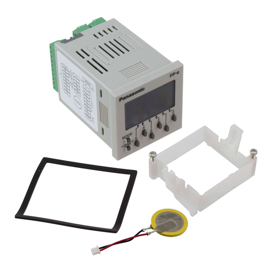
3.1.2 Mounting and Removing the Unit Mounting the unit Insert the unit into the mounting panel opening from its front and mount the mounting frame from the unit’s rear all the way not to have any space with the mounting panel. In addition, secure the mounting frame using screws. -
Page 32: Terminal Layout Diagram And Terminal Block Wiring
3.2 Terminal Layout Diagram and Terminal Block Wiring 3.2.1 Terminal layout diagram -Terminal layout diagram -Wiring diagram 3.2.2 Terminal block wiring Terminal block used and suitable wire A screw-down terminal block (from Phoenix Contact Co.) or equivalent is used. The suitable wires are shown below. - Page 33 Suitable screwdriver When tightening the terminals of the terminal block, use a screwdriver (Phoenix Contact Co. Product No.1205037) with a blade size of 0.4 X 2.5 (Model No. SZS 0.4 X 2.5) The tightening torque should be 0.22Nm to 0.25 Nm (2.3 kgfcm to 2.5 kgfcm) Model No.
-
Page 34: Power Supply Wiring
3.3 Power Supply Wiring 3.3.1 Power supply wiring Power supply wire To minimize adverse effects from noise, twist the wires of the power supply cable. Power supply type -To protect the system against erroneous voltage from the power supply line, use an insulated power supply with an internal protective circuit. -
Page 35: Grounding
3.3.2 Grounding Grounding to prevent noise Under normal conditions, the inherent noise resistance is sufficient. However, in situations of excessive noise, ground the instrument to increase noise suppression. Use an exclusive ground - For grounding purpose, use wiring with a minimum of 2 mm . -
Page 36: Wiring Of Input And Output
3.4 Wiring of Input and Output 3.4.1 Input wiring - Connection of photoelectric sensor and proximity sensor - Precaution when using LED-equipped reed switch When a LED is connected in series to an input contact such as LED-equipped reed switch, make sure that the ON voltage applied to the FP-e input terminal is greater than 19.2V DC. - Page 37 - Precaution when using two-wire type sensor When the input of FP-e does not turn off because of leakage current from the two-wire type sensors (e.g. photoelectric sensor and proximity sensor), the use of a bleeder resistor is recommended, as shown in the diagram on the left.
-
Page 38: Output Wiring
3.4.2 Output wiring Protective circuit for inductive loads -With an inductive load, a protective circuit should be installed in parallel with the load. -When switching DC inductive loads with relay output type, be sure to connect a diode across the ends of the load. -
Page 39: Wiring Com. Port
3.5 Wiring COM Port Terminal layout - Power supply and COM. port - COM. Port specifications *Note 2 COM. port type RX232C RS485 Isolation status with the Non-isolated Isolated internal circuit Transmission distance 15 m 1200 m 300, 600, 1200, 2400, 4800, 9600, *Note 3, 4 Baud rate 9600, 19200 bit/s... - Page 40 - Settings when shipped from factory System register Description No.412 Computer Link Character bit: 8 bits Parity check: odd No.413 Stop bit: 1 bit Header: STX not exist Terminator: CR No.414 Baud rate: 9600 bit/s No.415 Unit No.: 1 No.416 Modem: Not enable Reference: B.3 System register list - Suitable wires (twisted wire)
- Page 41 - Recommended cables for RS485 communication Use the transmission cables shown below for the FP-e RS485 communication system. Conductor Insulator Cable Cable Resistance Applicable cables Diameter Size Material Thickness (at 20 °C) HITACHI 0.5 mm Max. Twist pair Max. Approx. ×...
-
Page 42: Safety Measures
3.6 Safety Measures 3.6.1 Safety measures System design In applications in which FP-e is used, malfunctions may occur for the following reasons: -Power on timing difference between the FP-e system and input/output or mechanical power devices. -Response time lag when a momentary power failure occurs. -Abnormality in the FP-e unit, external power supply, or other devices. -
Page 43: Momentary Power Failures
3.6.2 Momentary power failures Operation of momentary power failures If the duration of the power failure is less than 10 ms, the FP-e unit continues to operate. If the power is turned off for 10 ms or longer, operation changes depending on the combination of units, the power supply voltage, and other factors. -
Page 44: Memory Backup Battery
3.7 Memory backup battery 3.7.1 Installation of memory backup battery (For FP-e unit with a calendar timer function) Although FP-e units with a calendar timer have a built-in lithium battery, a lithium battery connector is not connected to an FP-e unit connector. Follow the procedure as shown below to connect them. 1. -
Page 45: Display And Settings In N (Normal) Mode
Chapter 4 Display and Settings in N (Normal) Mode Phone: 800.894.0412 - Fax: 888.723.4773 - Web: www.clrwtr.com - Email: info@clrwtr.com... -
Page 46: Display And Operation In N (Normal) Mode
4.1 Display and operation in N (Normal) mode Operation examples - Values of EV0 and SV0 are displayed in the upper and lower sections of the controller screen respectively, using the F180 (SCR) instruction. - Pressing the operation switches (“0” to “5”) when the value (indicated in decimal or hexadecimal system) is displayed in the lower section changes the value in each digit. -
Page 47: Instructions To Control The Display
4.2 Instructions to control the display : Screen display instruction, Number of steps: 9 4.2.1 F180 (SCR) Screen display instructions in the N and S modes of FP-e unit The FPWIN GR wizard facilitates the programming. S1: Used to specify the registration screen. S2: Used to specify the head of the screen display control data (3 words). - Page 48 - Specifying the “S1” registration screen Display type of the FP-e unit can be specified. Values for “S1” Display type N mode 1 st screen N mode 2 nd screen S mode 1 st screen S mode 2 nd screen - Flag conditions R9007 Turns ON when the area specified using the...
- Page 49 word High byte (Display control: Upper section) Digit delete digit digit digit 0: Displayed, digit 1: Not displayed digit Color 00: Undefined (Displayed in green when defined) Color 01: Green 10: Red 11: Orange Zero 0: Available suppression 1: Not available (All digits displayed) * When a value with a decimal point is to be displayed in the “Signed Dec 5 digits”...
- Page 50 - Examples of control register word “0 0 0 0 0 0 0 0 1 0 0 0 0 0 1 1” = H83 ↑ ↑ ↑ ↑ Upper/Lower section SV PV ● display word “0 1 0 0 0 0 0 0 0 0 0 0 0 0 0 0”...
- Page 51 - Display description and data 7-segment display data Conversion data (for 1 digit) Value 7-segment display (for 1 digit) Phone: 800.894.0412 - Fax: 888.723.4773 - Web: www.clrwtr.com - Email: info@clrwtr.com...
-
Page 52: F180 (Scr) Instruction: Fpwin Gr Wizard
4.2.2 F180 (SCR) instruction: FPWIN GR Wizard Using the FPWIN GR wizard facilitates the programming. ↓ * FPWIN GR Ver. 2.2 or higher can be used with the FP-e unit. Customers who use the FPWIN GR Ver.2 software can upgrade it through our HP free of charge. -
Page 53: F181 (Dsp) : Screen Change Instruction Number Of Steps: 3
4.2.3 F181 (DSP) : Screen change instruction Number of steps: 3 FP-e unit display can be specified. - Available memory areas A: Can be specified N/A: Cannot be specified (Unit: Word) Index modifier Display mode and No. (0 to 7 can be specified.) - Operation The FP-e display mode is changed to the one specified using “S.”... -
Page 54: N Mode Sample Program
4.3 N mode sample program - Sample program - Screen display On N mode 1 screen, EV0 (red) and SV0 (orange) are displayed in the upper and lower sections respectively. On N mode 2 screen, EV1 (red) and SV1 (green) are displayed in the upper and lower sections respectively. -
Page 55: Display Screen And Lock With The Program
4.4 Display screen and lock with the program - Sample program - Program operation Turning ON the “R0” to “R6” switches the screen to be displayed. Note: Even if the “MODE” switch or the “1/2/SET” switch is pressed under the condition that the “R0”... - Page 56 4-12 Phone: 800.894.0412 - Fax: 888.723.4773 - Web: www.clrwtr.com - Email: info@clrwtr.com...
-
Page 57: Data Display And Settings In S (Switch) Mode
Chapter 5 Data Display and Settings in S (Switch) Mode Phone: 800.894.0412 - Fax: 888.723.4773 - Web: www.clrwtr.com - Email: info@clrwtr.com... -
Page 58: Display And Operation In S (Switch) Mode
5.1 Display and operation in S (Switch) mode The ASCII characters “FP-E-“ and the description of the “DT20” are displayed in the upper and lower sections of the controller screen respectively, using the F180 (SCR) instruction. The front switches can be used as the input contacts “X30” to “X37.” The switch can also be used to change the display description, and so on depending on the program. -
Page 59: S Mode Sample Program
5.2 S mode sample program - Sample program Screen display On S mode 1 screen, the ASCII character “FP-E-“ is displayed in the upper section in orange. Reference: See “ASCII character and 7-segment display” in Appendix A of this manual. On 2 screen, the data of “DT20”... - Page 60 Phone: 800.894.0412 - Fax: 888.723.4773 - Web: www.clrwtr.com - Email: info@clrwtr.com...
-
Page 61: Data Display And Settings In R (Register) Mode
Chapter 6 Data Display and Settings in R (Register) Mode Phone: 800.894.0412 - Fax: 888.723.4773 - Web: www.clrwtr.com - Email: info@clrwtr.com... -
Page 62: Display And Operation In R (Register) Mode
6.1 Display and operation in R (Register) mode 1. When the device type (DT, WR, SV, or EV) in the memory area is specified using the front operation switch, the specified device type data is displayed. - When “PV” blinks, the device type in the memory area can be specified. - The device No. -
Page 63: Operation In R (Register) Mode
6.2 Operation in R (Register) mode 6.2.1 Specifying the device type When “PV” blinks, the device type and No. can be changed. 1. Specifying the device type (Example of “EV”) Press the switch “4” until “EV” is displayed as shown above. Note: At this moment, the “EV0”... -
Page 64: Changing The Data
6.2.2 Changing the data 1. Switching to the data change mode - When the switch “5” is pressed for about 1 second, the “PV” display turns off and then the “SV” blinks. While the “SV” is blinking, data can be changed. Note: When the switch “5”... -
Page 65: Changing The Unit No. Of Com. Port
6.2.3 Changing the unit No. of COM. port The unit No. specified in the system register can be changed by the front switch (for Ver. 1.2 or higher). 1. Displaying the unit No. - Press the switch “4” to display the unit No. 2. - Page 66 Phone: 800.894.0412 - Fax: 888.723.4773 - Web: www.clrwtr.com - Email: info@clrwtr.com...
-
Page 67: I (I/O Monitor) Mode
Chapter 7 I (I/O Monitor) Mode Phone: 800.894.0412 - Fax: 888.723.4773 - Web: www.clrwtr.com - Email: info@clrwtr.com... -
Page 68: I/O Monitor
7.1 I/O monitor 1. I/O status of “WX0” and “WY0” can be monitored using 1 screen. - Example: Note: 1. “Y6” or higher does not exist for the FP-e external output, but it can be used as the contact on the program. 2. -
Page 69: Pid Control
Chapter 8 PID Control Phone: 800.894.0412 - Fax: 888.723.4773 - Web: www.clrwtr.com - Email: info@clrwtr.com... -
Page 70: Operation Of Pid Control
8.1 PID Control 8.1.1 Operation of PID control PID is a control method widely used in the instrumentation field involving feedback control of process quantities such as temperature, pressure, flow, and fluid level. - Proportional operation Proportional operation generates an output which is proportional to the input. The amount of control is held constant. -
Page 71: Pid Control Instruction
8.2 PID control instruction 8.2.1 F355 (PID) - PID control - Operands (Unit: Word) Constant Index modifier Starting number of PID parameter area (31 words) (A: Available, N/A: Not Available) - Descriptions · PID processing is performed to hold the measured value specified by [S+2] at the set value [S+1], and the result is output to [S+3]. - Page 72 - Descriptions of parameters 1. Control mode: [S] Select the type of PID processing and auto-tuning ON/OFF using the H constants. Value of [S] Control mode Auto-tuning: Not executed Auto-tuning: Executed Derivative type Reverse operation H8000 (PI-D) Forward operation H8001 Proportional-derivative Reverse operation H8002...
- Page 73 7. Proportional gain (Kp): [S + 6] Specify the coefficient used for PID processing. The set value × 0.1 will be the actual proportional gain. The setting range is K1 to K9999 (0.1 to 999.9, Specify the range in increments of 0.1.) When the auto-tuning is selected for the specified control mode, the set value is automatically adjusted and rewritten.
- Page 74 Note: - Precautions when executing auto-tuning When “Execute auto-tuning” is specified using the parameter table (control mode [S]), attention should be paid to the following points. ⋅ Before the auto-tuning is executed for the first time, confirm the range of the set values for [S] to [S + 30].
-
Page 75: Pid Control Sample Program
8.3 PID control sample program - PID control When a K-type thermocouple is connected with the thermocouple input of FP-e, PID temperature control can be easily conducted. (In addition, parameter setting can be automatically selected using “AUTO TUNING.”) - Thermocouple input specifications Item Description Number of input point... - Page 76 - (1) Screen display setting sample program Sample program Screen display setting: K0 (N mode 1 screen) Display control data: D0 to D2 Upper section display data: DT202 Lower section display data: DT201 Screen display Screen display : K0: N mode 1 screen setting Display control data...
- Page 77 - (3) PID processing sample program Sample program Program : Auto-tuning start (Auto-tuning is executed only once.) R100 : Auto-tuning is being executed. R130 : 16-bit data bit set When the most significant digit bit (K15) of the DT200 is “1”, auto-tuning starts.
- Page 78 - (4) Heater PWM control sample program Sample program Program DT203 : PID processing output : Heating time setting Heater control depending on PID processing result. To turn the heater ON (100 %) when the PID processing output DT203 is 100 % (K10000), divide the PID processing output DT203 (K10000) by 10 and write 100 % (1000 ms) into SV1 of heating timer.
-
Page 79: Example Of Temperature Control
8.4 Example of temperature control - Example of auto-tuning Control cycle: Ts = K100 (1 s) Selected parameter: Proportional gain (Kp) = K171 (17.1), Integral time (Ti) = K600 (60 s), Derivative time (Td) = K150 (15 s) Temperature (∗0.1 ℃) Output (%) Time (∗2 sec.) ⋅... - Page 80 Phone: 800.894.0412 - Fax: 888.723.4773 - Web: www.clrwtr.com - Email: info@clrwtr.com...
- Page 81 Chapter 9 Specifications Phone: 800.894.0412 - Fax: 888.723.4773 - Web: www.clrwtr.com - Email: info@clrwtr.com...
-
Page 82: Specifications
9.1 Specifications 9.1.1 General specifications Item Description Rated voltage 24V DC Operating voltage 21.6 to 26.4V DC range Allowed momentary 10 ms power off time Ambient temperature 0 to +55ºC Storage temperature -20 to +70ºC Ambient humidity 30 to 85%RH (at 25 ºC, non-condensing) Storage humidity 30 to 85%RH (at 25 ºC, non-condensing) Between insulated circuits: 500V AC,... - Page 83 9.1.2 Performance specifications AFPE224300 AFPE224302 AFPE224305 AFPE214325 AFPE224322 (Standard (Standard (Calendar (Thermo- (Thermo- Item Model type) type) timer couple input couple input RS232C RS485 type) type) type) RS232C RS232C RS485 Programming method/ Relay symbol/Cyclic operation Control method 14 points 12 points...
- Page 84 AFPE224300 AFPE224302 AFPE224305 AFPE214325 AFPE224322 (Standard (Standard (Calendar (Thermo- (Thermo- Item Model type) type) timer couple input couple input RS232C RS485 type) type) type) RS232C RS232C RS485 Note 6) Counter mode: Addition/subtraction (1-phase) - Input points: 4 ch. (Max.) - Max. speed: 10 kHz (total of 4 ch.) :Max.
- Page 85 (High-Speed Counter/Pulse Output/PWM Output) 9.1.3 Specifications Table of high-speed counter function specifications Input/Output counter Built-in Memory area used Performance specifica- Related number being used high- tions instruc- speed tions counter chan- On/Off Count Input Con- Elapsed Target Min. of Max. counting output mode contact...
-
Page 86: Performance Specifications
Table of pulse output function specifications Input/Output contact number Built-in Memory area used Performance Related being used high- specifica- instruc- speed tions for tions counter maximum channel output fre- Pulse Direc- Home Near Control Elapsed Target quency out- tional input home flag value... -
Page 87: Functions And Restrictions (High-Speed Counter/Pulse Output/Pwm Output)
9.1.4 Functions and Restrictions (High-Speed Counter/Pulse Output/PWM Output) Channel The same channel cannot be used by more than one function. Example of prohibited application: You cannot share CH.0 with the high-speed counter and pulse output functions. I/O number (input/output contact point) The number allocated to each function cannot be used for normal inputs or outputs. - Page 88 Restrictions for maximum counting speed/pulse output frequency The counting speed when using the high-speed counter function will differ depending on the counting mode as shown in the table. Example 1: While in the incremental input mode and using the two channels CH.0 and CH.1, if CH.0 is being used at 8 kHz, then CH.1 can be used up to 2 kHz.
-
Page 89: I/O Allocation
9.2 I/O Allocation - I/O Allocation of FP-e control unit Contact Description Note External input External input External input External input X0 to X5: Used for thermocouple input type. X6, X7: Not used. (Thermocouple input type) External input External input External input External input Not used. - Page 90 Contact Description Note External output External output External output External output External output External output Not used. Not used. Not used. Not used. Not used. Not used. Not used. Not used. Not used. Not used. “Mode”, “1/2/SET”, “0” to “5” switches: Locked. Switch is locked: 1 Switch lock (“0”...
-
Page 91: Relays,Memory Areas And Constants
9.3 Relays,memory Areas and Constants Number of Memory area available for use Item Function points Matsushita External input relay %IX0.0 - Turns on or off based on external X0 - X12F (See Note 3.) %IX12.15 input. External output relay %QX0.0 - Y0 - Y12F Outputs on or off state externally. - Page 92 Number of Memory area available for use Item Function points Matsushita Code for specifying 32 external External input relay 6 double DWX0 - DWX11 %ID0 -%ID11 input points as a double word (See Note 3.) words (32 bits) of data. Code for specifying 32 external External output relay 6 double...
- Page 93 3. The number of points noted above is the number reserved in the system. For the actual number of points available for use, refer to “I/O Allocation” in Appendix A. 4. Double words cannot be specified with FPWIN GR. Note 1) Hold type and non-hold type areas Model AFPE224300 AFPE224305 AFPE214325 (Standard type) (Calendar timer (Thermocouple input...
-
Page 94: Ascii Characters Displayed In The Fp-E Unit
9.4 ASCII characters displayed in the FP-e unit Available ASCII characters 9.4.1 Available output characters using ASCII Code 0xh 1xh 2xh 3xh 4xh 5xh 6xh 7xh DEL SPACE ” & ’ ∗ < ¥ > Note 1) If specifying a characters which cannot be output, a blank is output. Note 2) There is no discrimination between uppercase (41 h to 5Ah) and lowercase (61h to 7Ah) charac- ters. -
Page 95: Ascii Code And Display
ASCII code and display 9.4.2 Ascii code Ascii code Ascii code Ascii character Output image Ascii character Output image Ascii character Output image (SPACE) " & < > 9-15 Phone: 800.894.0412 - Fax: 888.723.4773 - Web: www.clrwtr.com - Email: info@clrwtr.com... - Page 96 Output image Ascii code Output image Ascii code Ascii character Ascii character Ascii code Output image Ascii character (DEL) Note) When specifying the control code (00h to 1Fh, or 7Fh), a blank appears. (No display is turned on.) 9-16 Phone: 800.894.0412 - Fax: 888.723.4773 - Web: www.clrwtr.com - Email: info@clrwtr.com...
-
Page 97: Dimensions
Chapter 10 Dimensions Phone: 800.894.0412 - Fax: 888.723.4773 - Web: www.clrwtr.com - Email: info@clrwtr.com... - Page 98 10.1 Dimensions 10-2 Phone: 800.894.0412 - Fax: 888.723.4773 - Web: www.clrwtr.com - Email: info@clrwtr.com...
-
Page 99: Appendix
Chapter 11 Appendix Phone: 800.894.0412 - Fax: 888.723.4773 - Web: www.clrwtr.com - Email: info@clrwtr.com... - Page 100 Appendix ..................11-1 11.1 System Registers / Special Internal Relays / Special Data Registers... 11-3 11.1.1 Table of System Registers for FP-e ............11-5 11.1.2 Table of Special Internal Relays for FP-e ..........11-9 11.1.3 Table of Special Data Registers for FP-e ..........11-13 11.2 Table of Basic Instructions ..............
-
Page 101: System Registers / Special Internal Relays / Special Data Registers
11.1 System Registers / Special Internal Relays / Special Data Registers Precation for System Registers What is the system register area • System registers are used to set values (parameters) which determine operation ranges and functions used. Set values based on the use and specifications of your program. •... - Page 102 (10) Input time constant settings (FP1/FP-M System registers 404 to 407) Changing the input signal width to be loaded enables to prevent the malfunctions caused by chattering or noises. (11) Number of temperature input averaging process settings (System register 409) The number of averaging times can be set in order to even out the variation in the input thermocouple values.
-
Page 103: Table Of System Registers For Fp-E
11.1.1 Table of System Registers for FP-e Default Name Descriptions value Starting number setting for 0 to 144 counter Hold type area starting number setting for timer and 0 to 144 counter Hold/ Hold type area starting Non- number setting for internal 0 to 63 (See note.) hold... - Page 104 FP-e Default Name Descriptions value Do not set input X0 as high-speed counter. Two-phase input (X0, X1) Two-phase input (X0, X1), Reset input (X2) Incremental input (X0) CH0: Incremental input (X0), Reset input (X2) Do not set Decremental input (X0) input X0 Decremental input (X0), Reset input (X2) incremental/decremental input (X0, X1)
- Page 105 FP-e Default Name Descriptions value Pulse catch input Not set Specify the input contacts used as pulse catch settings input. Inter- rupt- Specify the input contacts used as intrrupt input Interrupt input input. Not set settings Specify the effective interrupt edge. (When set: ON→OFF is valid) Note1) If the operation mode is set to two-phase, incremental/decremental, or incremental/decremental control, the setting for CH1 is invalid in part 2 of system register 400 and the setting for CH3 is...
- Page 106 FP-e Default Name Descriptions value Number of temperature input Tem- 0 to 50 average processing pera- times For default valeu “0”, the number of ture (Available PLC: average processing times is 20. inout model with thermocouple input) Unit No. setting 1 to 99 Disabled Modem connection: enabled/Disabled...
-
Page 107: Table Of Special Internal Relays For Fp-E
11.1.2 Table of Special Internal Relays for FP-e The special internal relays turn on and off under special conditions. The on and off states are not output externally. Writing is not possible with a programming tool or an instruction. Relay No.: Matsushita Name Description... - Page 108 FP-e Relay No.: Matsushita Name Description R9010 Always on relay Always on. %MX0.901.0 R9011 Always off relay Always off. %MX0.901.1 R9012 Scan pulse relay Turns on and off alternately at each scan. %MX0.901.2 Goes on for only the first scan after operation (RUN) has R9013 Initial (on type) pulse been started, and goes off for the second and subsequent...
- Page 109 FP-e Relay No.: Matsushita Name Description R9020 Turns off while the mode selector is set to PROG. RUN mode flag Turns on while the mode selector is set to RUN. %MX0.902.0 R9021 Not used %MX0.902.1 R9022 Not used %MX0.902.2 R9023 Not used %MX0.902.3 R9024...
- Page 110 FP-e Relay No.: Matsushita Name Description R9030 Not used %MX0.903.0 R9031 Not used %MX0.903.1 R9032 Not used %MX0.903.2 R9033 Print instruction Off: Printing is not executed. execution flag On: Execution is in progress. %MX0.903.3 R9034 RUN overwrite Goes on for ony the first scan following completion of a complete flag rewrite during RUN operation.
-
Page 111: Table Of Special Data Registers For Fp-E
11.1.3 Table of Special Data Registers for FP-e The special data registers are one word (16-bit) memory areas which store specific information. (A: Available, N/A: Not available) Register Read Writ- Name Descriptions Matsushita -ing DT9000 Self-diagnostic error The self-diagnostic error code is stored here code when a self-diagnostic error occurs. - Page 112 FP-e (A: Available, N/A: Not available) Register Read Writ Name Descriptions Matsushita -ing -ing DT9020 Not used %MW5.9020 DT9021 Not used %MW5.9021 The current scan time is stored here. Scan time DT9022 Scan time (current is calculated using the formula: Note) value) %MW5.9022...
- Page 113 FP-e (A: Available, N/A: Not available) Register Read Writ Name Descriptions Matsushita -ing -ing DT9036 Not used %MW5.9036 Operation auxiliary The number of data that match the searched DT9037 register for search data is stored here when F96 (SRC) insturction instruction %MW5.9037 is executed.
- Page 114 FP-e (A: Available, N/A: Not available) Register Read Writ Name Descriptions Matsushita -ing -ing The target value (24-bit data) of the high-speed DT9050 counter specified by the high-speed counter High-speed %MW5.9050 instruction is stored here. Target values have counter been preset for the various instructions to be target value used when the high-speed counter related DT9051...
- Page 115 FP-e (A: Available, N/A: Not available) Register Read Writ Name Descriptions Matsushita -ing -ing Clock/calendar The year, month, day, hour, minute, second and DT9054 setting day-of-the-week data for the calender timer is %MW5.9054 (minute/second) stored. The built-in calendar timer will operate correctly through the year 2099 and supports DT9055 Clock/calendar...
- Page 116 FP-e (A: Available, N/A: Not available) Register Read Writ Name Descriptions Matsushita -ing -ing Error code is sotred here when a communication error occurs. Serial DT9059 communication %MW5.9059 error code DT9060 Step ladder process (0 to 15) %MW5.9060 Indicates the startup condition of the step ladder DT9061 Step ladder process process.
- Page 117 FP-e (A: Available, N/A: Not available) Register Read Writ Name Descriptions Matsushita -ing -ing DT9104 High-speed The elapsed value (24-bit data) for the high- counter speed conter is stored here. The value can be %MW5.9104 elapsed read and written by executing the F1 (DMV) DT9105 value instruciton.
-
Page 118: Table Of Basic Instructions
11.2 Table of Basic Instructions Steps Name Boolean Symbol Description (*1) Sequence basic instructions Start Begins a logic operation with a Form A (normally open) 1 (2) contact. Start Not Begins a logic operation with a Form B (normally closed) 1 (2) contact. - Page 119 Availability FP-M Name Sequence basic instructions Start Start Not AND Not OR Not Leading edge start Trailing edge start Note: • A: Available, N/A: Not available 1) In the FP2/FP2SH/FP10SH, when using X1280, Y1280, R1120 (special internal relay included), L1280, T256, C256 or anything beyond for the ST, ST/, OT, AN, AN/, OR and OR/ instructions, the number of steps is shown in parentheses.
- Page 120 Steps Name Boolean Symbol Description (*1) Leading AN↑ Connects a Form A (normally open) contact serially only edge AND for one scan when the leading edge of the trigger is detected. Trailing edge AN↓ Connects a Form A (normally open) contact serially only for one scan when the trailing edge of the trigger is detected.
- Page 121 Availability FP-M Name Leading edge AND Trailing edge Leading edge OR Trailing edge Leading edge out Trailing edge Alternative AND stack OR stack Push stack Read stack Pop stack Leading edge differential Trailing edge differential Note: • A: Available, N/A: Not available 11-23 Phone: 800.894.0412 - Fax: 888.723.4773 - Web: www.clrwtr.com - Email: info@clrwtr.com...
- Page 122 Steps Name Boolean Symbol Description (*1) Leading Turns on the contact for only one scan when the leading edge differ- edge of the trigger is detected. The leading edge detection ential (initial is possible on the first scan. execution type) Output is set to and held at on.
- Page 123 Availability FP-M Name Leading edge differ- ential (initial execution type) Reset Keep No operation Note: • A: Available, N/A: Not available 1) In the FP2/FP2SH/FP10SH, when using Y1280, R1120 (special internal relay included), L1280 or anything beyond for the KP instruction, the number of steps is shown in parentheses. Also, in the FP2/FP2SH/FP10SH, when a relay number has an index modifier, the number of steps is shown in parentheses.
- Page 124 Steps Name Boolean Symbol Description (*1) Basic function instructions On-delay After set value “n” x 0.001 seconds, timer contact “a” is set 3 (4) timer to on. After set value “n” x 0.01 seconds, timer contact “a” is set 3 (4) to on.
- Page 125 Availability FP-M Name Basic function instructions On-delay timer TML (*1) On-delay timer TMR On-delay timer TMX On-delay timer TMY Auxiliary timer (16-bit) Auxiliary timer (32-bit) Counter UP/DOWN counter Note: • A: Available, N/A: Not available 1) This instruction is available for FP0 C10, C14, C16, C32 CPU Ver. 2.0 or later/FP0 T32C. 11-27 Phone: 800.894.0412 - Fax: 888.723.4773 - Web: www.clrwtr.com - Email: info@clrwtr.com...
- Page 126 Name Boolean Symbol Description Steps Shift register Shifts one bit of 16-bit [word internal relay (WR)] data to 1 (2) the left. (*1) Left/right F119 Shifts one bit of 16-bit data range specified by “D1” and shift register (LRSR) “D2” to the left or to the right. Control instructions Master Starts the master control program.
- Page 127 Availability FP-M Name Shift register Left/right shift register Control instructions Master control relay Master control relay Jump Label Auxiliary jump Label Note: • A: Available, N/A: Not available 1) In the FP2/FP2SH/FP10SH, when internal relay WR240 or higher is used, the number of steps is the number in parentheses.
- Page 128 Name Boolean Symbol Description Steps Loop LOOP The program jumps to the label instruction and continues 4 (5) from there (the number of jumps is set in “S”). (*1) Label Break Stops program execution when the predetermined trigger turns on in the TEST/RUN mode only. The operation of program is ended.
- Page 129 Availability FP-M Name Loop Label Break Conditional Eject Step ladder instructions Start step Next step NSTL Next step NSTP Clear step Clear multi- ple steps Step end Note: • A: Available, N/A: Not available 1) In the FP2/FP2SH/FP10SH, when the number “n” in a loop instruction has an index modifier, the number of steps is the number in parentheses.
- Page 130 Name Boolean Symbol Description Steps Subroutine instructions Subroutine CALL Executes the specified subroutine. When returning to the 2 (3) call main program, outputs in the subroutine program are (*1) maintained. Output off FCAL Executes the specified subroutine. When returning to the 4 (5) type subrou- main program, all outputs in the subroutine program are...
- Page 131 Availability FP-M Name Subroutine instructions Subroutine call Output off type subrou- tine call Subroutine entry Subroutine return Interrupt instructions Interrupt Interrupt return Interrupt control (*2) Note: • A: Available, N/A: Not available 1) In the FP2/FP2SH/FP10SH, when the number “n” of a subroutine program has an index modifier, the number of steps is the number in paretheses.
- Page 132 Name Boolean Symbol Description Steps Special setting instructions Communica- SYS1 Change the communication conditions for the COM port or tion condi- tool port based on the contents specified by the character tions setting constant. Password Change the password specified by the PLC based on the setting contents specified by the character constant.
- Page 133 Availability FP-M Name Special setting instructions Communica- Note2) tion condi- tions setting Password setting Interrupt setting PLC link time setting MEWTOCOL -COM response control High-speed counter operation mode changing System registers “No. 40 to No. 47” changing 11-35 Phone: 800.894.0412 - Fax: 888.723.4773 - Web: www.clrwtr.com - Email: info@clrwtr.com...
- Page 134 Name Boolean Symbol Description Steps Data compare instructions 16-bit data Begins a logic operation by comparing two 16-bit data in compare the comparative condition “S1=S2”. (Start) ST<> Begins a logic operation by comparing two 16-bit data in the comparative condition “S1<S2” or “S1>S2”. ST>...
- Page 135 Availability FP-M Name Data compare instructions 16-bit data compare (Start) 16-bit data compare (Start) ST<> 16-bit data compare (Start) ST> 16-bit data compare (Start) ST>= 16-bit data compare (Start) ST< 16-bit data compare (Start) ST<= Note: • A: Available, N/A: Not available 11-37 Phone: 800.894.0412 - Fax: 888.723.4773 - Web: www.clrwtr.com - Email: info@clrwtr.com...
- Page 136 Name Boolean Symbol Description Steps 16-bit data Connects a Form A (normally open) contact serially by compare comparing two 16-bit data in the comparative condition (AND) “S1=S2”. AN<> Connects a Form A (normally open) contact serially by comparing two 16-bit data in the comparative condition “S1<S2”...
- Page 137 Availability FP-M Name 16-bit data compare (AND) 16-bit data compare (AND) AN<> 16-bit data compare (AND) AN> 16-bit data compare (AND) AN>= 16-bit data compare (AND) AN< 16-bit data compare (AND) AN<= Note: • A: Available, N/A: Not available 11-39 Phone: 800.894.0412 - Fax: 888.723.4773 - Web: www.clrwtr.com - Email: info@clrwtr.com...
- Page 138 Name Boolean Symbol Description Steps 16-bit data Connects a Form A (normally open) contact in parallel by compare comparing two 16-bit data in the comparative condition (OR) “S1=S2”. OR<> Connects a Form A (normally open) contact in parallel by comparing two 16-bit data in the comparative condition “S1<S2”...
- Page 139 Availability FP-M Name 16-bit data compare (OR) 16-bit data compare (OR) OR<> 16-bit data compare (OR) OR> 16-bit data compare (OR) OR>= 16-bit data compare (OR) OR< 16-bit data compare (OR) OR<= Note: • A: Available, N/A: Not available 11-41 Phone: 800.894.0412 - Fax: 888.723.4773 - Web: www.clrwtr.com - Email: info@clrwtr.com...
- Page 140 Name Boolean Symbol Description Steps 32-bit data STD= Begins a logic operation by comparing two 32-bit data in compare the comparative condition “(S1+1, S1)=(S2+1, S2)”. (Start) STD<> Begins a logic operation by comparing two 32-bit data in the comparative condition “(S1+1, S1)<(S2+1, S2)” or “(S1+1, S1)>(S2+1, S2)”.
- Page 141 Availability FP-M Name 32-bit data compare (Start) STD= 32-bit data compare (Start) STD<> 32-bit data compare (Start) STD> 32-bit data compare (Start) STD>= 32-bit data compare (Start) STD< 32-bit data compare (Start) STD<= Note: • A: Available, N/A: Not available 11-43 Phone: 800.894.0412 - Fax: 888.723.4773 - Web: www.clrwtr.com - Email: info@clrwtr.com...
- Page 142 Name Boolean Symbol Description Steps 32-bit data AND= Connects a Form A (normally open) contact serially by compare comparing two 32-bit data in the comparative condition (AND) “(S1+1, S1)=(S2+1, S2)”. AND<> Connects a Form A (normally open) contact serially by comparing two 32-bit data in the comparative condition “(S1+1, S1)<(S2+1, S2)”...
- Page 143 Availability FP-M Name 32-bit data compare (AND) AND= 32-bit data compare (AND) AND<> 32-bit data compare (AND) AND> 32-bit data compare (AND) AND>= 32-bit data compare (AND) AND< 32-bit data compare (AND) AND<= Note: • A: Available, N/A: Not available 11-45 Phone: 800.894.0412 - Fax: 888.723.4773 - Web: www.clrwtr.com - Email: info@clrwtr.com...
- Page 144 Name Boolean Symbol Description Steps 32-bit data ORD= Connects a Form A (normally open) contact in parallel by compare comparing two 32-bit data in the comparative condition (OR) “(S1+1, S1)=(S2+1, S2)”. ORD<> Connects a Form A (normally open) contact in parallel by comparing two 32-bit data in the comparative condition “(S1+1, S1)<(S2+1, S2)”...
- Page 145 Availability FP-M Name 32-bit data compare (OR) ORD= 32-bit data compare (OR) ORD<> 32-bit data compare (OR) ORD> 32-bit data compare (OR) ORD>= 32-bit data compare (OR) ORD< 32-bit data compare (OR) ORD<= Note: • A: Available, N/A: Not available 11-47 Phone: 800.894.0412 - Fax: 888.723.4773 - Web: www.clrwtr.com - Email: info@clrwtr.com...
- Page 146 Name Boolean Symbol Description Steps Floating STF= Begins a logic operation by comparing two 32-bit data in point type the comparative condition “(S1+1, S1)=(S2+1, S2)”. real number data compare (Start) STF<> Begins a logic operation by comparing two 32-bit data in the comparative condition “(S1+1, S1)<(S2+1, S2)”...
- Page 147 Availability FP-M Name Floating point Note) Note) Note) Note) Note) type real number data compare (Start) STF= Floating point Note) Note) Note) Note) Note) type real number data compare (Start) STF<> Floating point Note) Note) Note) Note) Note) type real number data compare (Start)
- Page 148 Name Boolean Symbol Description Steps Floating ANF= Connects a Form A (normally open) contact serially by point type comparing two 32-bit data in the comparative condition real number “(S1+1, S1)=(S2+1, S2)”. data compare (AND) ANF<> Connects a Form A (normally open) contact serially by comparing two 32-bit data in the comparative condition “(S1+1, S1)<(S2+1, S2)”...
- Page 149 Availability FP-M Name Floating Note) Note) Note) Note) Note) point type real number data compare (AND) ANF= Floating Note) Note) Note) Note) Note) point type real number data compare (AND) ANF<> Floating Note) Note) Note) Note) Note) point type real number data compare (AND) ANF>...
- Page 150 Name Boolean Symbol Description Steps Floating ORF= Connects a Form A (normally open) contact in parallel by point type comparing two 32-bit data in the comparative condition real number “(S1+1, S1)=(S2+1, S2)”. data compare (OR) ORF<> Connects a Form A (normally open) contact in parallel by comparing two 32-bit data in the comparative condition “(S1+1, S1)<(S2+1, S2)”...
- Page 151 Availability FP-M Name Floating point type real number data compare (OR) ORF= Floating point type real number data compare (OR) ORF<> Floating point type real number data compare (OR) ORF> Floating point type real number data compare (OR) ORF>= Floating point type real number data compare...
-
Page 152: Table Of High-Level Instructions
11.3 Table of High-level Instructions The high-level instructions are expressed by the prefixes “F” or “P” with numbers. For most of the high- level instructions, “F” and “P” types are available. The differences between the two types are explained as follows: •... - Page 153 Availability FP1 (*1) FP-M (*1) Name Data transfer instructions (*2) (*2) Note: • A: Available, N/A: Not available 1) For the FP0/FPΣ/FP-X/FP-e/FP1/FP-M, the P type high-level instructions are not available. 2) The instruction is available for FP2/FP2SH CPU Ver. 1.5 or later. 11-55 Phone: 800.894.0412 - Fax: 888.723.4773 - Web: www.clrwtr.com - Email: info@clrwtr.com...
- Page 154 Num- Name Boolean Operand Description Steps Block copy COPY S, D1, D2 The data of “S” is transferred to the all area PCOPY between “D1” and “D2”. Data read ICRD S1, S2, D The data stored in the expansion memory of the IC from IC PICRD card or ROM specified by “S1”...
- Page 155 Availability FP1 (*1) FP-M (*1) Name (*2) (*2) Control instruction Binary arithmetic instructions Note: • A: Available, N/A: Not available 1) For the FP0/FPΣ/FP-X/FP-e/FP1/FP-M, the P type high-level instructions except for P13 (PICWT) instruction are not available. 2) This instruction is available for FP0 T32C and FP0 C10/C14/C16/C32 CPU Ver. 2.0 or later. 11-57 Phone: 800.894.0412 - Fax: 888.723.4773 - Web: www.clrwtr.com - Email: info@clrwtr.com...
- Page 156 Num- Name Boolean Operand Description Steps 32-bit data S1, S2, D (S1+1, S1)+(S2+1, S2)→(D+1, D) addition 16-bit data S, D (D)-(S)→(D) subtraction 32-bit data S, D (D+1, D)-(S+1, S)→(D+1, D) subtraction 16-bit data S1, S2, D (S1)-(S2)→(D) subraction 32-bit data S1, S2, D (S1+1, S1)-(S2+1, S2)→(D+1, D) subtraction...
- Page 157 Availability FP1 (*1) FP-M (*1) Name Note: • A: Available, N/A: Not available 1) For the FP0/FPΣ/FP-X/FP-e/FP1/FP-M, the P type high-level instructions are not available. 11-59 Phone: 800.894.0412 - Fax: 888.723.4773 - Web: www.clrwtr.com - Email: info@clrwtr.com...
- Page 158 Num- Name Boolean Operand Description Steps 16-bit data (D)-1→(D) decrement 32-bit data (D+1, D)-1→(D+1, D) decrement PD-1 32-bit data S1, S2, D (S1+1, S1)x(S2+1, S2)→(D+1, D) multiplication PD*D (result in 32 bits) BCD arithmetic instructions 4-digit S, D (D)+(S)→(D) BCD data addition 8-digit S, D...
- Page 159 Availability FP1 (*1) FP-M (*1) Name BCD arithmetic instructions Note: • A: Available, N/A: Not available 1) For the FP0/FPΣ/FP-X/FP-e/FP1/FP-M, the P type high-level instructions are not available. 11-61 Phone: 800.894.0412 - Fax: 888.723.4773 - Web: www.clrwtr.com - Email: info@clrwtr.com...
- Page 160 Num- Name Boolean Operand Description Steps 8-digit S1, S2, D (S1+1, S1)-(S2+1, S2)→(D+1, D) BCD data PDB- subraction 4-digit S1, S2, D (S1)X(S2)→(D+1, D) BCD data multiplication 8-digit S1, S2, D (S1+1, S1)X(S2+1, S2)→(D+3, D+2, D+1, D) BCD data PDB* multiplication 4-digit S1, S2, D...
- Page 161 Availability FP1 (*1) FP-M (*1) Name Note: • A: Available, N/A: Not available 1) For the FP0/FPΣ/FP-X/FP-e/FP1/FP-M, the P type high-level instructions are not available. 11-63 Phone: 800.894.0412 - Fax: 888.723.4773 - Web: www.clrwtr.com - Email: info@clrwtr.com...
- Page 162 Num- Name Boolean Operand Description Steps Data compare instructions 16-bit data S1, S2 (S1)>(S2)→R900A: on compare PCMP (S1)=(S2)→R900B: on (S1)<(S2)→R900C: on 32-bit data DCMP S1, S2 (S1+1, S1)>(S2+1, S2)→R900A: on compare PDCMP (S1+1, S1)=(S2+1, S2)→R900B: on (S1+1, S1)<(S2+1, S2)→R900C: on 16-bit data S1, S2, S3 (S1)>(S3)→R900A: on...
- Page 163 Availability FP1 (*1) FP-M (*1) Name Data compare instructions Logic operation instructions Note: • A: Available, N/A: Not available 1) For the FP0/FPΣ/FP-X/FP-e/FP1/FP-M, the P type high-level instructions are not available. 11-65 Phone: 800.894.0412 - Fax: 888.723.4773 - Web: www.clrwtr.com - Email: info@clrwtr.com...
- Page 164 Num- Name Boolean Operand Description Steps Data conversion instructions Block check S1, S2, S3, Creates the code for checking the data specified by code PBCC “S2” and “S3” and stores it in “D”. calculation The calculation method is specified by “S1”. Hexadecimal HEXA S1, S2, D...
- Page 165 Availability FP1 (*1) FP-M (*1) Name Data conversion instructions Note: • A: Available, N/A: Not available 1) For the FP0/FPΣ/FP-X/FP-e/FP1/FP-M, the P type high-level instructions are not available. 11-67 Phone: 800.894.0412 - Fax: 888.723.4773 - Web: www.clrwtr.com - Email: info@clrwtr.com...
- Page 166 Num- Name Boolean Operand Description Steps ASCII code DABI S1, S2, D Converts the ASCII code specified by “S1” and → 32-bit PDABI “S2” to 32 bits of binary data and stores it in (D+1, binary data 16-bit binary S, D Converts the 16 bits of binary data specified by “S”...
- Page 167 Availability FP1 (*1) FP-M (*1) Name Note: • A: Available, N/A: Not available 1) For the FP0/FPΣ/FP-X/FP-e/FP1/FP-M, the P type high-level instructions are not available. 11-69 Phone: 800.894.0412 - Fax: 888.723.4773 - Web: www.clrwtr.com - Email: info@clrwtr.com...
- Page 168 Num- Name Boolean Operand Description Steps 32-bit data DABS Gives the absolute value of the data of (D+1, D). absolute PDABS 16-bit data Extends the 16 bits of data in “D” to 32 bits in (D+1, sign PEXT extension Decode DECO S, n, D Decodes part of the data of “S”...
- Page 169 Availability FP1 (*1) FP-M (*1) Name Data shift instructions Note: • A: Available, N/A: Not available 1) For the FP0/FPΣ/FP-X/FP-e/FP1/FP-M, the P type high-level instructions are not available. 11-71 Phone: 800.894.0412 - Fax: 888.723.4773 - Web: www.clrwtr.com - Email: info@clrwtr.com...
- Page 170 Num- Name Boolean Operand Description Steps Data table CMPW S, D1, D2 Transfer “S” to “D1”. Any parts of the data between shift-in and PCMPW “D1” and “D2” that are 0 are compressed, and compress shifted in order toward “D2”. F100 Right shift of D, n...
- Page 171 Availability FP1 (*1) FP-M (*1) Name F100 P100 F101 P101 F102 P102 F103 P103 F105 P105 F106 P106 F108 P108 F109 P109 F110 P110 F111 P111 F112 P112 Note: • A: Available, N/A: Not available 1) For the FP0/FPΣ/FP-X/FP-e/FP1/FP-M, the P type high-level instructions are not available. 11-73 Phone: 800.894.0412 - Fax: 888.723.4773 - Web: www.clrwtr.com - Email: info@clrwtr.com...
- Page 172 Num- Name Boolean Operand Description Steps F113 Left shift of WBSL D1, D2 Shifts the one digit of the areas by “D1” and “D2” to P113 one hexade- PWBSL the left. cimal digit (4-bit) FIFO instructions F115 FIFO buffer FIFT n, D The “n”...
- Page 173 Availability FP1 (*1) FP-M (*1) Name F113 P113 FIFO instructions F115 P115 F116 P116 F117 P117 Basic function instructions F118 F119 Data rotate instructions F120 P120 F121 P121 F122 P122 F123 P123 Note: • A: Available, N/A: Not available 1) For the FP0/FPΣ/FP-X/FP-e/FP1/FP-M, the P type high-level instructions are not available. 11-75 Phone: 800.894.0412 - Fax: 888.723.4773 - Web: www.clrwtr.com - Email: info@clrwtr.com...
- Page 174 Num- Name Boolean Operand Description Steps F125 32-bit data DROR D, n Rotate the number of bits specified by “n” of the P125 right rotate PDROR double words data (32 bits) specified by (D+1, D) to the right. F126 32-bit data DROL D, n Rotate the number of bits specified by “n”...
- Page 175 Availability FP1 (*1) FP-M (*1) Name F125 P125 F126 P126 F127 P127 F128 P128 Bit manipulation instructions F130 P130 F131 P131 F132 P132 F133 P133 F135 P135 F136 P136 Note: • A: Available, N/A: Not available 1) For the FP0/FPΣ/FP-X/FP-e/FP1/FP-M, the P type high-level instructions are not available. 11-77 Phone: 800.894.0412 - Fax: 888.723.4773 - Web: www.clrwtr.com - Email: info@clrwtr.com...
- Page 176 Num- Name Boolean Operand Description Steps Basic function instruction F137 Auxiliary STMR S, D Turn on the specified output and R900D after 0.01 s × set value. timer (16-bit) Special instructions F138 Hours, min- HMSS S, D Converts the hour, minute and second data of P138 utes and sec- PHMSS...
- Page 177 Availability FP1 (*1) FP-M (*1) Name Basic function instruction F137 Special instructions F138 P138 (*2) F139 P139 (*2) F140 P140 F141 P141 Note: • A: Available, N/A: Not available 1) For the FP0/FPΣ/FP-X/FP-e/FP1/FP-M, the P type high-level instructions are not available. 2) On the FP0 it is only possible to use F138 and F139 with the T32 type.
- Page 178 Num- Name Boolean Operand Description Steps F142 Watching The time (allowable scan time for the system) of watching dog timer is changed to “S” × 0.1 (ms) for P142 dog timer PWDT update that scan. F143 Partial I/O IORF D1, D2 Updates the I/O from the number specified by “D1”...
- Page 179 Availability FP1 (*1) FP-M (*1) Name F142 P142 F143 P143 F144 (*2) (*2) (*2) F145 P145 F146 P146 F145 (*3) P145 F146 (*3) P146 F145 (*3) (*3) P145 F146 (*3) (*3) P146 F147 F148 P148 Note: • A: Available, N/A: Not available 1) For the FP0/FPΣ/FP-X/FP-e/FP1/FP-M, the P type high-level instructions are not available.
- Page 180 Num- Name Boolean Operand Description Steps F149 Message Displays the character constant of “S” in the P149 display PMSG connected programming tool. F150 Data read READ S1, S2, n, Reads the data from the intelligent unit. P150 from intelli- PREAD gent unit F151 Data write...
- Page 181 Availability FP1 (*1) FP-M (*1) Name F149 P149 F150 P150 (*2) F151 P151 (*2) F152 P152 F153 P153 F154 P154 F155 P155 F156 P156 F157 P157 (*3) F158 P158 (*3) F159 P159 (*4) (*4) F161 P161 (*4) (*4) Note: • A: Available, N/A: Not available 1) For the FP0/FPΣ/FP-X/FP-e/FP1/FP-M, the P type high-level instructions are not available.
- Page 182 Num- Name Boolean Operand Description Steps BIN arithmetic instruction √(S)→(D) F160 Double word DSQR S, D P160 (32-bit) data PDSQR square root Special instructions (High-speed counter instructions) High-speed S, DT9052 Performs high-speed counter and Pulse output counter and controls according to the control code specified by Pulse output “S”.
- Page 183 Availability FP1 (*1) FP-M (*1) Name BIN arithmetic instruction F160 P160 Special instructions (High-speed counter instructions) (*1) F162 F163 F164 F165 Note: • A: Available, N/A: Not available 1) The elapsed value area varies depending on the channel being used. 11-85 Phone: 800.894.0412 - Fax: 888.723.4773 - Web: www.clrwtr.com - Email: info@clrwtr.com...
- Page 184 Num- Name Boolean Operand Description Steps High speed counter/Pulse output instruction for FP0, FP-e F166 High-speed HC1S n, S, Yn Turns output Yn on when the elapsed value of the counter built-in high-speed counter reaches the target value output set of (S+1, S).
- Page 185 Availability FP1 (*1) FP-M (*1) Name High speed counter/Pulse output instruction for FP0, FP-e F166 F167 F168 F169 F170 Note: • A: Available, N/A: Not available The elapsed value area varies depending on the channel being used. 11-87 Phone: 800.894.0412 - Fax: 888.723.4773 - Web: www.clrwtr.com - Email: info@clrwtr.com...
- Page 186 Num- Name Boolean Operand Description Steps High speed counter/Pulse output instruction for FPΣ/FP-X High-speed S, DT90052 Performs high-speed counter and Pulse output counter and controls according to the control code specified by Pulse output “S”. The control code is stored in DT90052. controls Change and FPΣ:...
- Page 187 Availability FP1 (*1) FP-M (*1) Name High speed counter/Pulse output instruction for FPΣ/FP-X F166 F167 F171 F172 F173 F174 F175 F176 Note1) The elapsed value area differs depending on used channels. 11-89 Phone: 800.894.0412 - Fax: 888.723.4773 - Web: www.clrwtr.com - Email: info@clrwtr.com...
- Page 188 Num- Name Boolean Operand Description Steps Screen display instructions F180 FP-e screen S1, S2, S3, Register the screen displayed on the FP-e. display registration F181 FP-e screen Specify the screen to be displayed on the FP-e. display switching Basic function instruction F183 Auxiliary DSTM...
- Page 189 Availability FP1 (*1) FP-M (*1) Name Screen display instructions F180 F181 Basic function instruction F183 Data transfer instructions F190 P190 F191 P191 Logic operation instructions F215 P215 F216 P216 F217 P217 F218 P218 F219 P219 Data conversion instructions F230 P230 (*3) (*2) (*2)
- Page 190 Num- Name Boolean Operand Description Steps F235 16-bit binary S, D Converts the 16-bit binary data of “S” to gray data → Gray P235 PGRY codes, and the converted result is stored in the “D”. code conversion F236 32-bit binary DGRY S, D Converts the 32-bit binary data of (S+1, S) to gray...
- Page 191 Availability FP1 (*1) FP-M (*1) Name F235 P235 F236 P236 F237 P237 F238 P238 F240 P240 F241 P241 F250 (*2) F251 (*2) Character strings instructions F257 P257 F258 P258 F259 P259 F260 P260 F261 P261 Note: • A: Available, N/A: Not available 1) For the FPΣ, FP-X, the P type high-level instructions are not available.
- Page 192 Num- Name Boolean Operand Description Steps F262 Retrieving LEFT S1, S2, D These instructions retrieve a specified number of P262 data from characters from the left side of the character string. character strings (left side) F263 Retrieving a MIDR S1, S2, S3, These instructions retrieve a character string P263 character...
- Page 193 Availability FP1 (*1) FP-M (*1) Name F262 P262 F263 P263 F264 P264 F265 P265 Integer type data processing instructions F270 P270 (*2) F271 P271 (*2) F272 P272 (*2) F273 P273 (*2) F275 P275 (*2) F276 P276 (*2) Note: • A: Available, N/A: Not available 1) For the FPΣ/FP-X, the P type high-level instructions are not available.
- Page 194 Num- Name Boolean Operand Description Steps F277 Sort (word SORT S1, S2, S3 The word data with sign from the area specified by P277 data (16-bit)) PSORT “S1” to “S2” are sorted in ascending order (the smallest word is first) or descending order (the largest word is first).
- Page 195 Availability FP1 (*1) FP-M (*1) Name F277 P277 (*2) F278 P278 (*2) F282 P282 (*2) F283 P283 Integer type non-linear function instructions F285 P285 (*2) F286 P286 (*2) F287 P287 (*2) F288 P288 (*2) F289 P289 (*2) F290 P290 (*2) Note: •...
- Page 196 Num- Name Boolean Operand Description Steps BCD type real number operation instructions F300 BCD type BSIN S, D SIN(S1+1, S1)→(D+1, D) P300 sine PBSIN operation F301 BCD type BCOS S, D COS(S1+1, S1)→(D+1, D) P301 cosine PBCOS operation F302 BCD type BTAN S, D TAN(S1+1, S1)→(D+1, D)
- Page 197 Availability FP1 (*1) FP-M (*1) Name BCD type real number operation instructions F300 P300 F301 P301 F302 P302 F303 P303 F304 P304 F305 P305 Note: • A: Available, N/A: Not available 11-99 Phone: 800.894.0412 - Fax: 888.723.4773 - Web: www.clrwtr.com - Email: info@clrwtr.com...
- Page 198 Num- Name Boolean Operand Description Steps Floating-point type real number operation instructions F309 Floating- S, D (S+1, S)→(D+1, D) P309 point type PFMV data move F310 Floating- S1, S2, D (S1+1, S1)+(S2+1, S2)→(D+1, D) P310 point type data addition Floating- S1, S2, D F311 (S1+1, S1)−(S2+1, S2)→(D+1, D)
- Page 199 Availability FP1 (*1) FP-M (*1) Name Floating-point type real number operation instructions F309 P309 (*2) F310 P310 (*2) F311 P311 (*2) F312 P312 (*2) F313 P313 (*2) F314 P314 (*2) F315 P315 (*2) F316 P316 (*2) F317 P317 (*2) F318 P318 (*2) Note:...
- Page 200 Num- Name Boolean Operand Description Steps F319 Floating- ATAN S, D (S+1, S)→(D+1, D) P319 point type PATAN data arctangent operation F320 Floating- S, D LN(S+1, S)→(D+1, D) P320 point type data natural logarithm F321 Floating- S, D EXP(S+1, S)→(D+1, D) point type P321 PEXP...
- Page 201 Availability FP1 (*1) FP-M (*1) Name F319 P319 (*2) F320 P320 (*2) F321 P321 (*2) F322 P322 (*2) F323 P323 (*2) F324 P324 (*2) F325 P325 (*2) F326 P326 (*2) Note: • A: Available, N/A: Not available 1) For the FP0, FPΣ, FP-X and FP-e, the P type high-level instructions are not available. 2) The instruction is available for FP0 T32C and FP0 C10/C14/C16/C32 CPU Ver.
- Page 202 Num- Name Boolean Operand Description Steps F327 Floating- S, D Converts real number data specified by (S+1, S) to P327 point type PINT the 16-bit integer data with sign (the largest integer data to 16-bit not exceeding the floating-point data), and the integer con- converted data is stored in “D”.
- Page 203 Availability FP1 (*1) FP-M (*1) Name F327 P327 (*2) F328 P328 (*2) F329 P329 (*2) F330 P330 (*2) Note: • A: Available, N/A: Not available 1) For the FP0, FPΣ, FP-X and FP-e, the P type high-level instructions are not available. 2) The instruction is available for FP0 T32C and FP0 C10/C14/C16/C32 CPU Ver.
- Page 204 Num- Name Boolean Operand Description Steps F331 Floating- ROFF S, D Converts real number data specified by (S+1, S) to P331 point type PROFF the 16-bit integer data with sign (rounding the first data to 16-bit decimal point off), and the converted data is stored integer con- in “D”.
- Page 205 Availability FP1 (*1) FP-M (*1) Name F331 P331 (*2) F332 P332 (*2) F333 P333 (*2) F334 P334 (*2) F335 P335 (*2) F336 P336 (*2) F337 P337 (*2) Note: • A: Available, N/A: Not available 1) For the FP0, FPΣ, FP-X and FP-e, the P type high-level instructions are not available. 2) The instruction is available for FP0 T32C and FP0 C10/C14/C16/C32 CPU Ver.
- Page 206 Num- Name Boolean Operand Description Steps F338 Floating- S, D The angle data in radians (real number data) P338 point type PDEG specified in (S+1, S) is converted to angle data in data radian degrees, and the result is stored in (D+1, D). →...
- Page 207 Availability FP1 (*1) FP-M (*1) Name F338 P338 (*2) Floating-point type real number data processing instructions F345 P345 F346 P346 F347 P347 F348 P348 F349 P349 F350 P350 Note: • A: Available, N/A: Not available 1) For the FP0, FPΣ, FP-X and FP-e, the P type high-level instructions are not available. 2) The instruction is available for FP0 T32C and FP0 C10/C14/C16/C32 CPU Ver.
- Page 208 Num- Name Boolean Operand Description Steps F351 Floating- FMIN S1, S2, D Searches the minimum value in the real number P351 point type PFMIN data table between the area selected with “S1” and data mini- “S2”, and stores it in the (D+1, D). The address mum value relative to “S1”...
- Page 209 Availability FP1 (*1) FP-M (*1) Name F351 P351 F352 P352 F353 P353 F354 (*5) P354 (*3) (*3) Time series processing instruction F355 (*1) F356 (*4) (*4) Compare instructions F373 P373 F374 P374 Note: • A: Available, N/A: Not available 1) For the FP0, FPΣ, FP-X and FP-e, the P type high-level instructions are not available. 2) For the FP0, the instruction is available for the T32C and C10, C14, C16, C32 CPU Ver.
- Page 210 Num- Name Boolean Operand Description Steps Index register bank processing instructions F410 Setting the SETB Index register (I0 to ID) bank number change over. P410 index regis- PSETB ter bank number F411 Changing the CHGB Index register (I0 to ID) bank number change over P411 index regis- PCHGB...
- Page 211 Availability FP1 (*1) FP-M (*1) Name Index register bank processing instructions F410 P410 F411 P411 F412 P412 File register bank processing instructions F414 P414 F415 P415 F416 P416 Note: • A: Available, N/A: Not available 11-113 Phone: 800.894.0412 - Fax: 888.723.4773 - Web: www.clrwtr.com - Email: info@clrwtr.com...
-
Page 212: Table Of Error Codes
11.4 Table of Error codes Difference in ERROR display There are differences in the way errors are displayed depending on the model. Model Display Display method FP1,FP-M,FP2,FP3,FP10SH ERROR. Continually lit FPΣ,FP0, FP-X ERROR/ALARM Flashes/contunually lit FP-e Screen display ERR. Continually lit Error Confirmation When ERROR Turns ON When the “ERROR”... - Page 213 -Self-diagnostic Error This error occurs when the control unit (CPU unit) self-diagnostic function detects the occurrence of an abnormality in the system. The self-diagnostic function monitors the memory abnormal detection, I/O abnomal detection, and other devices. When a self-diagnostic error occurs - The ERROR turns on or flashes.
- Page 214 Table of Syntax Check Error Opera- Error Name tion Description and steps to take code status A program with a syntax error has been Syntax written. Stops A A A A A A A A A ⇒ Change to PROG. mode and correct error the error.
- Page 215 Opera- Error Name tion Description and steps to take code status The program is too large to compile in the program memory. ⇒ Change to PROG. mode and reduce Compile the total number of steps for the memory Stops A A A A A program.
- Page 216 Table of Self-Diagnostic Error Opera- Error Name tion Description and steps to take code status Probably a hardware abnormality CPU error Stops ⇒Please contact your dealer. error1 error2 Probably an abnormality in the internal Stops RAM. error3 ⇒Please contact your dealer. error4 error5 FP-e,FP0,FPΣ,and FP1...
- Page 217 Opera- Error Name tion Description and steps to take code status Configu- A parameter error was detected in the ration Stops MEWNET-W2 configuration area. Set parameter a correct parameter. error Interrupt Probably a hardware abnormality. Stops ⇒ Please contact your dealer. error 0 An interrupt occurred without an interrupt request .
- Page 218 Opera- Error Name tion Description and steps to take code status I/O mapping for remote I/O terminal MEWNET-F boards,remote I/O terminal units and slave I/O I/O link is not correct. terminal Stops ⇒Re-configure the I/O map for slave mapping stations according to the I/O points of error the slave stations.
- Page 219 Opera- Error Name tion Description and steps to take code status An abnormality in an intelligent unit. FPΣ, FP-X: Check the contetns of special data register “DT90006” and locate the abnormal FP intelligent unit (application cassette for FP-X). FP2,FP2SH,and FP10SH: Check the contents of special data registers DT90006,DT90007 and locate the abnormal intelligent unit.Then check...
- Page 220 Opera- Error Name tion Description and steps to take code status Scan time required for program execution exceeds the setting of the system watching dog timer. System ⇒ Check the program and modify it so watching Selec- that the program can execute a scan within the specified time.
- Page 221 Opera- Error Name tion Description and steps to take code status S-LINK error Occurs only in FP0-SL1 When one of the S-LINK errors (ERR1, 3 or 4) has been deteced,error code E46 (remote I/O (S-LINK) communication Selec- error) is stored. table Selection of operation status using system register27:...
- Page 222 Opera- Error Name tion Description and steps to take code status The voltage of the backup battery lowered or the backup battery of conrol unit is not installed. Backup Conti- ⇒ Check the installation of the backup Note battery A A A A A A A battery and then replace battery if nues...
- Page 223 Opera- Error Name tion Description and steps to take code status The error specified by the F148 E100 Self- (ERR)/P148(PERR) instruction is diagnostic Stop A A A A occurred. E199 error set ⇒ Take steps to clear the error condition by F148 according to the specification you chose.
- Page 224 Table of MEWTOCOL-COM Communication Error Error Name Description code NACK error Link system error WACK error Link system error Unit No. overlap Link system error Transmission format Link system error error Link unit hardware Link system error error Unit No. setting error Link system error No support error Link system error...
- Page 225 Error Name Description code An abnormality occurred when loading RAM to ROM/IC memory card.There may be a problem with the ROM or IC memory card. -When loading,the specified contents exceeded the capacity. External memory -Write error occurs. error -ROM or IC memory card is not installed. -ROM or IC memory card does not conform to specifications -ROM or IC memory card board is not installed.
-
Page 226: Mewtocol-Com Communication Commands
11.5 MEWTOCOL-COM Communication Commands Table of MEWTOCOL-COM commands Command name Code Description Reads the on and off status of contact. (RCS) - Specifies only one point. Read contact area - Specifies multiple contacts. (RCP) - Specifies a range in word units. (RCC) Turns contacts on and off. -
Page 227: Hexadecimal/Binary/Bcd
11.6 Hexadecimal/Binary/BCD BCD data Decimal Hexadecimal Binary data (Binary Coded Decimal) 0000 00000000 00000000 0000 0000 0000 0000 0001 00000000 00000001 0000 0000 0000 0001 0002 00000000 00000010 0000 0000 0000 0010 0003 00000000 00000011 0000 0000 0000 0011 0004 00000000 00000100 0000 0000 0000 0100 0005... -
Page 228: Ascii Codes
11.7 ASCII Codes 11-130 Phone: 800.894.0412 - Fax: 888.723.4773 - Web: www.clrwtr.com - Email: info@clrwtr.com... - Page 229 Record of changes Manual No. Date Desceiption of changes ARCT1F369E DEC., 2002 First edition ARCT1F369E-1 JUL., 2003 edition PDF Only Addition of Chapter 8 “PID Control” AFCT1F369E-2 edition PDF Only APR., 2003 Addition of functions available for Ver. 1.2 or higher Addition of new models (RS485 type) - AFPE224302 - AFPE214322...
Need help?
Do you have a question about the AFPE224300 and is the answer not in the manual?
Questions and answers