Panasonic MINAS A4 Connection Manual
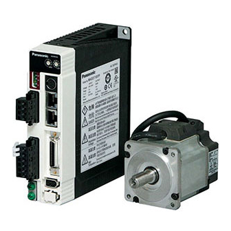
Servo drive
Hide thumbs
Also See for MINAS A4:
- Features (1 page) ,
- Instruction manual (366 pages) ,
- Technical reference (26 pages)
Table of Contents
Advertisement
Quick Links
Download this manual
See also:
Instruction Manual
Panasonic MINAS A4
Supported Series: Panasonic MINAS A4 series Servo Drive.
HMI Setting:
Parameters
Recommended
PLC type
Panasonic MINAS A4
PLC I/F
RS232
Baud rate
9600
8
Data bits
Parity
None
Stop bits
1
Axis no.
0 (master station only)
Device Address:
Bit/Word
Device type
B
Command 20
B
Command 27
B
Command 28
W
Command 01
W
Command 05
W
Command 06
W
Command 21
W
Command 22
W
Command 24
W
Command 25
W
Command 26
W
Command 84
W
Command 90
Options
2400 ~ 57600
0 ~ F (slave)
Format
Range
D
0 ~ 7
DD
0 ~ 31
DD
0 ~ 31
D
0
DD
0 ~ 11
DD
0 ~ 11
D
0 ~ 1
D
0 ~ 1
D
0
D
0
D
0 ~ 1
D
0
D
0
PLC Connection Guide
Notes
Memo
States
(Note 3)
Input Signal
(Note 3)
Output Signal
(Note 3)
CPU Version (Numeric
format:16-bit Hex)
Driver Version (ASCII / 12 words)
Motor Version (ASCII / 12 words)
command pulse counter
(Numeric format: 32-bit Signed)
feedback pulse counter
(Numeric format: 32-bit Signed)
present speed
(Numeric format: 16-bit Unsigned)
present torque
(Numeric format: 16-bit Unsigned)
present deviation counter
(Numeric format: 32-bit Signed)
write parameter to EEPROM
(Note 1)
present Alarm Data
Advertisement
Table of Contents

Related Manuals for Panasonic MINAS A4


Summary of Contents for Panasonic MINAS A4
- Page 1 PLC Connection Guide Panasonic MINAS A4 Supported Series: Panasonic MINAS A4 series Servo Drive. HMI Setting: Parameters Recommended Options Notes PLC type Panasonic MINAS A4 PLC I/F RS232 Baud rate 9600 2400 ~ 57600 Data bits Parity None Stop bits Axis no.
- Page 2 For example: “address_00” is mapping to “Parameter_00”. (Please refer to Panasonic MINAS A4 Series User Manual.) 3. Device address type can define MINAS A4 Driver’s command list. Command 20, Command 27, and Command 28 are Bit type, use “Operating range” to map communication order status.
- Page 3 PLC Connection Guide Wiring Diagram: The following is the view from the soldering point of a cable. MINAS A4 Driver CNX4 Port Diagram 1 cMT3151 cMT Series eMT3070/ eMT3105 / eMT3120 / eMT3150 eMT Series MT8073iE / MT8102iE MT-iE MT8092XE...
- Page 4 PLC Connection Guide Diagram 2 cMT-SVR cMT Series MT8070iE / MT6070iE / MT8100iE / MT8121iE / MT8150iE / MT-iE MT8071iE / MT6071iE / MT8072iE / MT6072iE / MT8073iE / MT8101iE / MT8102iE / MT8103iE MT8121XE / MT8150XE / MT8090XE MT-XE COM1 RS232 8P RS232...
- Page 5 PLC Connection Guide MINAS A4 Driver MINAS A4 Driver CNX3 Port CNX4 Port 3 TX 5 RX 4 GND 4 GND 8P Mini-Din Male MINAS A4 Driver 7 D- 7 D- CNX3 / CNX4 Port 8 D+ 8 D+ RS485 cable / DVOP1970-005...
Need help?
Do you have a question about the MINAS A4 and is the answer not in the manual?
Questions and answers