Panasonic FP0R User Manual
Hide thumbs
Also See for FP0R:
- User manual (349 pages) ,
- Programming manual (1334 pages) ,
- User manual (92 pages)
Table of Contents
Advertisement
Quick Links
Advertisement
Table of Contents

Related Manuals for Panasonic FP0R


Summary of Contents for Panasonic FP0R
- Page 1 PROGRAMMABLE CONTROLLERS FP0R User’s Manual...
- Page 2 This manual and everything described in it are copyrighted. You may not copy this manual, in whole or part, without written consent of Panasonic Electric Works Europe AG (PEWEU). PEWEU pursues a policy of continuous improvement of the design and performance of its products.
- Page 3 Important symbols One or more of the following symbols may be used in this documentation: DANGER! The warning triangle indicates especially important safety instructions. If they are not adhered to, the results could be fatal or critical injury. CAUTION Indicates that you should proceed with caution. Failure to do so may result in injury or significant damage to instruments or their contents, e.g.
- Page 4 system variables (FPWIN Pro only) programming examples For documentation on a particular unit used with the FP0R, please refer to the hardware manual for that unit. All manuals can be downloaded from the Panasonic Web site (http://www.panasonic-electric-works.com).
- Page 5 Programming Conventions The programming examples in this manual are designed for FPWIN Pro. For FPWIN GR examples, please refer to: FP0R User’s Manual ARCT1F475E Most of the sample programs were written in Ladder Diagram. In FPWIN Pro, you can also program in Structured Text, Function Block Diagram, Instruction List, and Sequential Function Chart.
-
Page 6: Table Of Contents
1. Safety Measures ..............13 Safety Measures..................14 2. Overview ................17 Features....................18 Unit Types....................20 2.2.1 CPU......................20 2.2.2 FP0/FP0R I/O Expansion Units..............21 2.2.3 FP0 Intelligent Units ................. 22 2.2.4 FP Series Link Units................. 23 2.2.5 Power Supply Unit..................23 2.2.6 Accessories .................... - Page 7 Parts and Functions Expansion Units ............51 Expansion Input Specifications ..............53 Expansion Output Specifications..............54 Terminal Layout..................57 5. I/O Allocation ................ 61 General.....................62 CPU......................63 FP0/FP0R Expansion Units..............64 6. Installation and Wiring............67 Installation ....................68 6.1.1 Installation Environment and Space............68 6.1.2 Using DIN Rails ..................70 6.1.3...
- Page 8 Table of Contents 6.1.3.1 Slim Type Mounting Plate ............... 71 6.1.3.2 Flat Type Mounting Plate ..............72 Connecting FP0/FP0R Expansion Units..........75 Safety Instructions for Wiring..............76 Wiring the Power Supply ................. 78 6.4.1 Grounding....................79 Input and Output Wiring................81 6.5.1...
- Page 9 Table of Contents Communication Specifications ...............107 Communication Parameters..............110 7.4.1 Setting System Registers in PROG Mode ..........110 7.4.2 Changing Communication Mode in RUN Mode ........112 MEWTOCOL-COM.................113 7.5.1 Operation Outline for MEWTOCOL-COM Slave ........115 7.5.2 Command and Response Format ............116 7.5.3 Commands .....................118 7.5.4 Setting Communication Parameters ............119 7.5.4.1...
- Page 10 Table of Contents 7.7.2.3 Partial Use of Link Areas............... 157 7.7.2.4 Precautions for Allocating Link Areas ........... 159 7.7.3 Setting the Highest Station Number for a PLC Link....... 160 7.7.4 PLC Link 0 and 1 Allocation Setting............160 7.7.5 Monitoring....................161 7.7.6 PLC Link Response Time ..............
- Page 11 Table of Contents 8.3.5.2 Positioning Operations with a Double-Speed Inverter ....194 Pulse Output Function................196 8.4.1 Pulse Output Methods and Position Control Modes ......196 8.4.2 I/O Allocation ..................199 8.4.3 Instructions and System Variables............200 8.4.3.1 Writing the Pulse Output Control Code .........202 8.4.3.2 Writing and Reading the Elapsed Value of the Pulse Output ..206 8.4.3.3...
- Page 12 Table of Contents 10.2 Sampling Trace..................229 10.3 Input Time Constants................230 11. Troubleshooting ..............231 11.1 LED Display for Status Condition ............232 11.2 Operation on Error ................. 233 11.3 ERROR/ALARM LED is Flashing ............234 11.4 ERROR/ALARM LED is ON ..............235 11.5 All LEDs are OFF...................
- Page 13 Table of Contents 12.3 Relays and Memory Areas for FP0R............256 12.4 System Registers ...................258 12.4.1 Precautions When Setting System Registers ........258 12.4.2 Types of System Registers ..............258 12.4.3 Checking and Changing System Registers..........259 12.4.4 Table of System Registers ..............259 12.5 Error Codes ....................266 12.5.1 Error Codes E1 to E8 ................266...
-
Page 14: Safety Measures
Chapter 1 Safety Measures... -
Page 15: Safety Measures
Safety Measures 1.1 Safety Measures Operating environment After installing the unit, make sure to use it within the range of the general specifications: Ambient temperature: 0°C–+55°C Ambient humidity: 10%–95% RH (at 25°C non-condensing) Pollution level: 2 Do not use the unit in the following environments: Direct sunlight Sudden temperature changes causing condensation... - Page 16 Safety Measures and output. If the power supply for input and output is turned off first, the CPU will detect the input fluctuations and may begin an unexpected operation. Before turning on the power When turning on the power for the first time, be sure to take the precautions given below. ...
-
Page 18: Overview
Chapter 2 Overview... -
Page 19: Features
Overview 2.1 Features The FP0R is an ultra compact PLC (programmable logic controller) with high-speed processing capabilities and a large memory capacity. The controller uses the comprehensive FP instruction set and is programmed with FPWIN Pro or FPWIN GR. With FPWIN Pro, programming according to IEC 61131-3 is possible. - Page 20 The FP0 compatibility mode enables programs that have been used on an existing FP0 to be activated on the FP0R with no further modifications. Also, since both units have an identical shape and terminal layout, there is no need to check the installation space or change the...
-
Page 21: Unit Types
Overview 2.2 Unit Types The following units are available for the FP0R: 2.2.1 CPU 16k types (program capacity: 16k steps) Number of Power Type Input Output Connection COM port Product no. I/O points supply ― AFP0RC10RS 10 (6/4) RS232C AFP0RC10CRS... -
Page 22: Fp0/Fp0R I/O Expansion Units
(NPN): 0.2A RS485 AFP0RF32MT (built-in RS232C FRAM) AFP0RF32CP Transistor (PNP): 0.2A RS485 AFP0RF32MP Total number (input points/output points) 2.2.2 FP0/FP0R I/O Expansion Units Number of Power Type Input Output Connection Product no. I/O points supply 24V DC 8 (8/–) –... -
Page 23: Fp0 Intelligent Units
Power Type Input Output Connection Product no. I/O points supply 24V DC 16 (16/–) – – MIL connector FP0R-E16X ±COM terminal 24V DC 16 (8/8) 24V DC Relay: 2A Terminal block FP0R-E16RS ±COM terminal 24V DC Transistor: 16 (8/8) –... -
Page 24: Fp Series Link Units
AFP0523BLUED Maintenance part (packed with FP0 power supply cable Cable length: 1m AFP0581 FP0/FP0R expansion units) FP0R/FP power supply cable Maintenance part (packed with CPU) Cable length: 1m AFPG805 Terminal block socket; Phoenix connector (2 pcs) AFP0802 maintenance parts (packed with relay output type) 40-pin MIL wire-press socket;... -
Page 25: Restrictions On Unit Combinations
CPU is limited. A maximum of three expansion units can be connected on the right side of the FP0R CPU, these expansion units being either I/O expansion units or intelligent units. A combination of relay output types and transistor output types is also possible. -
Page 26: Programming Tools
FPWIN GR Version 2 or later FP Memory Loader (AFP8670/AFP8671) to transfer programs and system registers can also be used. You can connect your PC to the FP0R with an RS232C FP0R programming cable or via the USB port. PC connection cable:... -
Page 27: Fp0 Program Compatibility
Overview 2.5 FP0 Program Compatibility Programs from the existing FP0 can only be used on the FP0R, if they: 1. conform to FP0R specifications, or 2. are executed in FP0 compatibility mode Using programs that conform to FP0R specifications This allows you to make maximum use of FP0R performance and functions. However, the... - Page 28 Overview No. of write blocks (words) FP0 [ms] FP0 compatibility mode [ms] 5 100 1 (64) 10 100 2 (128) 20 100 4 (256) 40 100 8 (512) 80 100 16 (1024) 160 100 32 (2048) 165 200 33 (2112) 205 200 41 (2624)
- Page 29 5. F169_PulseOutput_Jog, JOG operation There are two differences between the FP0 and the FP0R specifications: Count mode: The FP0R does not support the "no counting" setting. Instead, incremental counting is performed with the FP0 pulse output instructions set to "no counting".
-
Page 30: Cpu Types
Chapter 3 CPU Types... -
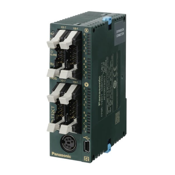
Page 31: Parts And Functions Cpu
CPU Types 3.1 Parts and Functions CPU C10/C14 C32/T32/F32 EXPANSION CONNECTOR Front view Right side view Left side view Operation status LEDs Display the current operation mode or the occurrence of an error. - Page 32 When performing remote switching with the programming tool, the position of the operation mode selector and the actual operation mode may differ. Verify the mode with the operation status LED. Otherwise, restart the FP0R and set the operation mode using the operation mode selector.
- Page 33 Used to secure an expansion unit. The hook is also used for installation on the flat type mounting plate (part no. AFP0804). Connector for FP0/FP0R expansion units Connects an FP0/FP0R expansion unit to the internal circuit. The connector is located under the seal. DIN rail attachment lever Used for easy attachment to a DIN rail.
-
Page 34: Input Specifications, Cpu
CPU Types 3.2 Input Specifications, CPU The input specifications below apply to all FP0R CPU types. Item Description Insulation method Optical coupler Rated input voltage 24V DC Operating voltage range 21.6–26.4V DC Rated input current 2.6mA C10: 6 C14, C16: 8... - Page 35 CPU Types Internal circuit diagram Internal circuit R1 9.1k R2 1k...
-
Page 36: Output Specifications, Cpu
CPU Types 3.3 Output Specifications, CPU Transistor types These output specifications apply to the CPU types C32 and C28. Description Insulation method Optical coupler Output type Open collector Rated load voltage 5V DC–24V DC 24V DC Operating load voltage range 4.75–26.4V DC 21.6–26.4V DC Max. - Page 37 CPU Types Internal circuit diagram [NPN] 24V DC 5~24V DC – Internal circuit Load Output circuit External power supply Output indicator LED Load power supply Output [PNP] – 24V DC Internal circuit Load Output circuit External power supply Output indicator LED Load power supply Output...
- Page 38 CPU Types Relay types (C10/C14) Item Description Output type 1a output Nominal switching capacity 2A 250V AC, 2A 30V DC (4.5A/common) (resistive load) C10: 2+1+1 Output points per common C14: 4+1+1 FALSE TRUE 10ms Response time TRUE FALSE 8ms Mechanical lifetime 20 000 000 operations (switching frequency: 180 operations/min)
-
Page 39: Terminal Layout
CPU Types 3.4 Terminal Layout 3.4.1 C10 CPU C10RS, C10CRS, C10RM, C10CRM X0-5 (NC) (NC) Y0-3 (NC) (NC) (The above illustration is the terminal block type.) Input Output Power supply... -
Page 40: C14 Cpu
CPU Types 3.4.2 C14 CPU C14RS, C14CRS, C14RM, C14CRM X0-7 Y0-5 (The above illustration is the terminal block type.) Input Output Power supply... -
Page 41: C16 Cpu
CPU Types 3.4.3 C16 CPU C16T, C16CT X0-7 Y0-7 (–) The COM terminals of the input circuits are connected internally. Input Connector front view Output C16P, C16CP X0-7 Y0-7 (–) The COM terminals of the input circuits are connected internally. Input Connector front view Output... -
Page 42: C32 Cpu
CPU Types 3.4.4 C32 CPU C32T, C32CT, T32CT, F32CT X0-7 X8-F Y0-7 Y8-F (–) (–) The (+) terminals as well as the (-) terminals of the output circuits are connected internally. Input Output Connector front view C32P, C32CP, T32CP, F32CP X0-7 X8-F Y0-7... -
Page 43: Backup And Clock/Calendar Functions
the clock/calendar function The FP0R-F32 CPU has a built-in FRAM, which allows saving all data without a backup battery. The FP0R-F32 type does not offer a clock/calendar function. Charging the battery The built-in backup battery is not charged when the unit is shipped. -
Page 44: Backup Function
25°C <51s/month 55°C <155s/month 3.5.1 Backup Function Additional hold areas which will be saved with a backup battery (FP0R-T32) or with the built-in FRAM (FP0R-F32) can be specified for the following memory areas: Timers/Counter (T/C) Internal relays (R) ... -
Page 45: Clock/Calendar Function
CPU Types CAUTION If the battery is empty and additional hold areas have been defined, the hold/non-hold operation becomes unstable. The data value will become indefinite. It is cleared to 0 the next time the power is turned on. Do not forget to monitor the battery status or to reset the hold areas to the default values if no battery is used. -
Page 46: Settings For Clock/Calendar Function
CPU Types 3.5.2.2 Settings for Clock/Calendar Function The clock/calendar values are backed up using a battery. Therefore, the clock/calendar function cannot be used unless a battery has been installed There are no default clock/calendar settings, so the programming tool or another means must be used to specify these values. -
Page 47: Sample Program For Fixed Schedule And Automatic Start
CPU Types LD Body 3.5.2.3 Sample Program for Fixed Schedule and Automatic Start In this example, the clock/calendar function is used to output the Y0 signal for one second at 8:30 a.m. every day. Here, the hour/minute data stored in special data register DT90053 is used to output the signal at the appointed time. - Page 48 CPU Types POU Header LD Body ST Body (DF(bStartCompensation)) then...
- Page 49 CPU Types (* Read the current time from the RTC *) dtbcdCurrent.MinSec:=sys_wClockCalendarMinSec; dtbcdCurrent.DayHour:=sys_wClockCalendarDayHour; dtbcdCurrent.YearMonth:=sys_wClockCalendarYearMonth; (* Decide whether to round up (seconds>=30) *) ((dtbcdCurrent.MinSec 16#00FF)>30) then (* To round up 1 minute (16#100) is added to the current time *) F157_ADD_DTBCD_TIMEBCD(s1_DTBCD := dtbcdCurrent, s2_TIMEBCD 16#100,...
-
Page 50: Expansion
Chapter 4 Expansion... -
Page 51: Expansion Method
Expansion 4.1 Expansion Method You can expand the FP0R by adding FP0 I/O expansion units (see page 21), FP0 intelligent units (see page 22) and FP Series link units (see page 23). The expansion units are connected to the right side of the CPU. Use the expansion connector and the expansion hooks on the side of the unit. -
Page 52: Parts And Functions Expansion Units
Expansion 4.2 Parts and Functions Expansion Units E8RS/E16RS E8RM/E16RM E8YRS E16Y E16X EXPANSION CONNECTOR Terminal block type MIL connector type Right side view (common to all expansion units) Power supply connector (24V DC) Use the power supply cable provided. Product no.: AFP0581... - Page 53 Expansion hook Used to secure an expansion unit. Connector for FP0/FP0R expansion units Connects an FP0/FP0R expansion unit to the internal circuit. The connector is located under the seal. DIN rail attachment lever Used for easy attachment to a DIN rail. The lever is also used for installation on a slim type...
-
Page 54: Expansion Input Specifications
Operation mode indicator LEDs All FP0 expansion units have been replaced by newer FP0R units with improved specifications. Limitations on the number of input points that are TRUE simultaneously Keep the number of input points per common which are simultaneously TRUE within the following range as determined by the ambient temperature. -
Page 55: Expansion Output Specifications
Expansion 4.4 Expansion Output Specifications Relay output specifications (E8RS/E8RM/E8YRS/E16RS/E16RM/E32RS) Item Description Output type Nominal switching capacity (resistive load) 2A 250V AC, 2A 30V DC (4.5A/common) E8R: 4 Output points per common E16R/E8YR/E32RS: 8 FALSE TRUE 10ms Response time TRUE FALSE 8ms Mechanical lifetime 20 000 000 operations (switching frequency: 180 operations/min) - Page 56 Operation mode indicator LEDs All FP0 expansion units have been replaced by newer FP0R units with improved specifications. Limitations on the number of input points that are TRUE simultaneously Keep the number of input points per common which are simultaneously TRUE within the following range as determined by the ambient temperature.
- Page 57 Expansion [PNP] – 24V DC Internal circuit Load Output circuit External power supply Output indicator LED Load power supply Output...
-
Page 58: Terminal Layout
Expansion 4.5 Terminal Layout E8RS, E8RM X0-3 Y0-3 (NC) (NC) (NC) (NC) (NC) (NC) (NC) (NC) Input Output Power supply E16R, E8YRS, E32RS X0-7 Y0-7 Input (no input for E8YRS) Output Power supply... - Page 59 Expansion E8X, E16T, E8YT X0-7 Y0-7 (–) The COM terminals of the input circuits are connected internally. Input (no input for E8YT) Output (no output for E8X) Connector front view E16X, E32T, E16YT X0-7 X8-F Y0-7 Y8-F (–) (–) The (+) terminals as well as the (-) terminals of the output circuits are connected internally. Input (no input for E16YT) Output (no output for E16X) Connector front view...
- Page 60 Expansion E16P, E8YP X0-7 Y0-7 (–) The COM terminals of the input circuits are connected internally. Input (no input for E8YT) Output Power supply E32P, E16YP X0-7 X8-F Y0-7 Y8-F (–) (–) The (+) terminals as well as the (-) terminals of the output circuits are connected internally. Input (no input for E16YP) Output Connector front view...
-
Page 62: I/O Allocation
Chapter 5 I/O Allocation... -
Page 63: General
1, 2, 3 ... 9 1, 2, 3 ... 9, A, B ... F On the FP0R and the FP0, the same numbers are used for inputs and outputs, e.g. X20, Y20. The usable I/O numbers depend on the unit type. See "FP0/FP0R Expansion... -
Page 64: Cpu
I/O Allocation 5.2 CPU The I/O allocation of the FP0R CPU is fixed. CPU type Number of I/O points I/O addresses Input X0–X5 Output Y0–Y3 Input X0–X7 Output Y0–Y5 Input X0–X7 Output Y0–Y7 Input X0–XF C32/T32/F32 Output Y0–YF... -
Page 65: Fp0/Fp0R Expansion Units
I/O allocation is performed automatically when an expansion unit is added and is determined by the installation location. Expansion units from the FP0/FP0R series are connected on the right side of the CPU. The I/O numbers are allocated from the unit nearest to the CPU in ascending order. - Page 66 I/O Allocation NOTE The data for each channel of the A/D and D/A conversion units FP0-A80, FP0-TC4/TC8, FP0-A04V/I, and FP0-RTD6 is converted and loaded with a user program that includes a switching flag to convert the data in 16-bit words (see corresponding manuals).
-
Page 68: Installation And Wiring
Chapter 6 Installation and Wiring... -
Page 69: Installation
Installation and Wiring 6.1 Installation Please follow the installation instructions carefully to prevent failure or malfunctions. 6.1.1 Installation Environment and Space Operating environment After installing the unit, make sure to use it within the range of the general specifications: Ambient temperature: 0–+55°C ... - Page 70 Installation and Wiring Do NOT install the CPU as shown below. Upside-down Upside-down Input and output connectors face down Input and output connectors on top Horizontal installation of the unit Do not install the unit above devices which generate heat such as heaters, transformers or large scale resistors.
-
Page 71: Using Din Rails
Installation and Wiring the connection of the programming tool. 6.1.2 Using DIN Rails The CPU can be easily attached to DIN rails. Procedure 1. Fit upper hook of unit onto DIN rail 2. Without moving upper hook, press on lower hook to fit unit into position Removal is very simple, too: Procedure EXPANSION... -
Page 72: Using Optional Mounting Plates
Installation and Wiring 6.1.3 Using Optional Mounting Plates Use M4 size pan-head screws for attaching the mounting plate to the mounting panel. The diagrams below show the dimensions of the mounting plates. 6.1.3.1 Slim Type Mounting Plate The mounting plate AFP0803 can be used alternatively to DIN-rail mounting. 4 mm 12.5 mm 10 mm... -
Page 73: Flat Type Mounting Plate
Installation and Wiring The following diagram shows the combination of the mounting plates AFP0803 when the maximum number of expansion units is used and the mounting hole dimensions: 75.0 25.0 25.0 25.0 φ5.0 ∅10.0 6.1.3.2 Flat Type Mounting Plate The flat type mounting plate (AFP0804) should only be used with a stand-alone CPU. It should not be used if an expansion unit is attached to the CPU. - Page 74 Installation and Wiring Installation Procedure 1. Raise expansion hooks on top and bottom of the unit 2. Press unit on mounting plate and align expansion hooks with plate 3. Push expansion hooks back into place Removal Procedure 1. Raise expansion hooks on top and bottom of the unit 2.
- Page 75 Installation and Wiring Attachment to DIN rail A unit with an attached flat type mounting plate can also be installed sideways on a DIN rail. DIN rail...
-
Page 76: Connecting Fp0/Fp0R Expansion Units
Installation and Wiring 6.2 Connecting FP0/FP0R Expansion Units The expansion units are connected to the right side of the CPU. Use the expansion connector and the expansion hooks on the side of the unit. Procedure 1. Peel seal on right side of the unit to expose expansion connector 2. -
Page 77: Safety Instructions For Wiring
Use an exclusive ground for each device. Momentary power failures The FP0R continues to operate normally for a certain period of time in case of a momentary power failure. We call this the momentary power off time. However, if the power failure exceeds this period of time, operation depends on the combination of units, the power supply voltage, etc. - Page 78 Installation and Wiring Protection of power supply An insulated power supply with an internal protective circuit should be used (FP0-PSA2 or FP-PS24-050). The power supply for the CPU is a non-insulated circuit, so if an incorrect voltage is directly applied, the internal circuit may be damaged or destroyed.
-
Page 79: Wiring The Power Supply
Installation and Wiring 6.4 Wiring the Power Supply Use the power supply cable provided. Attach as shown. Power supply cable (AFPG805) Brown: 24V DC Blue: 0V Green: function earth Specifications Rated voltage: 24V DC Operating voltage range: 21.6–26.4V DC NOTE To minimize adverse effects from noise, twist the brown and blue wires of ... -
Page 80: Grounding
Installation and Wiring Isolation of power supply systems Isolate the wiring systems to the CPU, input/output devices, and mechanical power apparatus. Mechanical power apparatus Input/output devices Circuit breaker Insulated DC power supply Power supply sequence Make sure the power supply of the CPU turns off before the power supply for input and output. - Page 81 Power supply line of FP0R with built-in 39V varistor Example 2: Do not ground the function earth terminal of the FP0R when grounding a plus terminal (+) of the power supply. In some computers, the SG terminal of the RS232C port is connected with the connector shielding.
-
Page 82: Input And Output Wiring
Do not route them through the same duct or wrap them up together. 6.5.1 Input Wiring For connecting input devices see the diagrams and recommendations given below. Relay output type NPN input PNP input Sensor Power supply for sensor FP0R Power supply for input Internal circuit Input terminal Relay... - Page 83 Installation and Wiring Open collector output type NPN output PNP output Sensor Output FP0R Power supply for input Internal circuit Input terminal Voltage output (universal output) type Sensor Output FP0R Power supply for input Internal circuit Input terminal Two-wire output type...
- Page 84 DC. In particular, take care when connecting a number of switches in series. LED-equipped Reed switch Contact 21.6V FP0R Input terminal Precaution when using a two-wire type sensor If the input of the PLC does not turn off because of leakage current from the two-wire type sensor (photoelectric sensor or proximity sensor), the use of a bleeder resistor is recommended, as shown below.
-
Page 85: Output Wiring
If the input of the PLC does not turn off because of the leakage current from the LED-equipped limit switch, the use of a bleeder resistor is recommended, as shown below. LED-equipped limit switch Bleeder resistor FP0R Input terminal Internal circuit Internal resistor of limit switch (k) Power supply for input Bleeder resistor (k) - Page 86 Installation and Wiring Using an AC inductive load (relay output type) FP0R Output terminal Load Surge absorber, e.g. resistance R: 50, capacitance C: 0.47F FP0R Output terminal Load Varistor Using a DC inductive load FP0R Output terminal Load ): 3 load Diode;...
-
Page 87: Protective Circuit For Capacitive Loads
Installation and Wiring 6.5.2.2 Protective Circuit for Capacitive Loads When connecting loads with large in-rush currents, connect a protection circuit as shown below to minimize their effect. FP0R Output terminal Load Resistor FP0R Output terminal Load Inductor... -
Page 88: Wiring The Mil Connector
Installation and Wiring 6.6 Wiring the MIL Connector The connector indicated below is supplied with transistor type CPUs and I/O expansion units. Use the wires indicated below. A pressure connection tool for connecting the wires is recommended. This connector can be ordered as an accessory. Ordering information Product no. - Page 89 Installation and Wiring Wiring method The wire end can be directly crimped without removing the wire's insulation, saving labor. After breaking off a contact from the carrier, proceed as follows: Procedure 1. Insert wire without removing its insulation until it stops 2.
-
Page 90: Wiring The Terminal Block
Installation and Wiring 6.7 Wiring the Terminal Block Screw-type terminal blocks are used. The suitable wires are given below. NOTE When removing the wire's insulation, be careful not to scratch the core wire. Do not twist the wires to connect them. ... - Page 91 Installation and Wiring Cross-sectional area [mm ] Size 0.25 AWG24 0.50 AWG20 0.75 AWG18 1.00 AWG18 0.5 x 2 AWG20 (for 2 pieces) The tightening torque should be 0.22–0.25Nm or less. Use a screwdriver with a blade size of 0.4 x 2.5. Wiring method Procedure 1.
-
Page 92: Wiring The Com Port
Installation and Wiring 6.8 Wiring the COM Port A screw-down connection type is used for the COM port. The suitable wires are given below. Symbol RS232C RS485 Signal Ground E terminal Receive Data (Input) Transmission line (-) Send Data (Output) Transmission line (+) NOTE ... - Page 93 Installation and Wiring Terminal block The communication connector manufactured by Phoenix Contact is used. Item Description Number of pins 3 Manufacturer Phoenix Contact Co. Model MKDS1/3-3.5 Product no. 1751400 Suitable wire Size Cross-sectional area [mm AWG28–16 0.08–1.25 Only use shielded twisted pair cables. It is recommended to ground the shielded part.
- Page 94 Installation and Wiring 3. Turn the screw clockwise to fix the wire in place RS485 connection diagram Bridge the E terminal and the free (-) terminal on the first and on the last station of the transmission line to terminate the data bus. NOTE Wiring should extend from one station to the next.
-
Page 95: Transmission Cables
Installation and Wiring 6.8.1 Transmission Cables Please use the following transmission cables. Conductor Insulator Cable Type diameter Size Resistance (at Thickness Material [mm] [mm] 20°C) [/km] Shielded twisted pair 0.5 33.4 0.5 7.8 Polyethylene (AWG20) VCTF 0.5 Polychlorinated 37.8 0.6 6.2 (AWG20) biphenyl... -
Page 96: Communication
Chapter 7 Communication... -
Page 97: Communication Modes
Program controlled PLC Link (MEWNET-W0) Modbus RTU Master/Slave Communication ports The FP0R is equipped with the following ports: TOOL port (RS232C interface) USB port (USB 2.0 Fullspeed interface) COM port (RS232C or RS485 interface) 7.1.1 Terminology in FPWIN Pro and FPWIN GR... -
Page 98: Program Controlled Communication
COM COM IN2 IN4 CAMERA MONITOR Receive buffer Bar code reader Receiving data Program controlled connection between the FP0R and an external device REFERENCE For detailed information on the program controlled communication mode, see "Program Controlled Communication" on page 126. -
Page 99: Plc Link
100. RS485 LD 0 LD 0 LD 0 LD 0 PLC Link connection between four FP0R units Station number of PLC Link register REFERENCE For detailed information on the PLC Link communication mode, see "PLC Link" on page 151. -
Page 100: Modbus Rtu Master/Slave
This communication mode uses the Modbus RTU protocol to exchange data between a master and one or more slaves. This is called 1:1 or 1:N communication. Modbus RTU connection between the FP0R and an external device Command message Response message There is a Modbus RTU master function and a Modbus RTU slave function. -
Page 101: Ports: Names And Principle Applications
Communication 7.2 Ports: Names and Principle Applications Port name Connector Communication mode MEWTOCOL-COM Slave TOOL port Mini DIN 5-pin connector Program controlled (in RUN mode only) USB port MEWTOCOL-COM Slave USB miniB type MEWTOCOL-COM Master/Slave Program controlled COM port 3-wire RS232C or 2-wire RS485 (screw type) ... -
Page 102: Com Port
Communication 7.2.2 COM Port This port is used to connect devices via RS232C or RS485 to enable data input/output. CPU types with a COM port for RS232C communication: C10CR, C14CR, C16C, C32C, T32C, F32C CPU types with a COM port for RS485 communication: C10MR, C14MR, C16M, C32M, T32M, F32M Symbol RS232C RS485... -
Page 103: Usb Port
Connecting the PLCs with a personal computer using a USB cable enables communication with our programming software. This communication method uses the USB as a virtual serial port, i.e. the FP0R connected via USB is treated by the PC as if connected via the COM port. The COM port number of the COM port allocated for the USB is fixed unless you change the number. -
Page 104: Installing The Usb Driver
A USB hub cannot be used. When multiple FP0R units are connected to one PC with the USB, they cannot communicate with the PC simultaneously. The PC can communicate with the FP0R that was connected first only, and it cannot communicate with the other FP0R. - Page 105 Communication Confirming COM Ports The FP0R connected to the PC via USB is treated as if connected via a COM port. It depends on your PC environment to which COM port the USB is allocated. Therefore, it is necessary to confirm the COM port number.
-
Page 106: Communication With The Programming Tool
Communication "CP210x USB to UART Bridge Controller (COM n)" is the COM port allocated. COM9 is allocated in the following display. NOTE If "? CP210x USB to UART Bridge Controller" appears in "Other devices" or "Unknown device" is indicated, the installation has failed. Reinstall the USB driver (see page 106). -
Page 107: Reinstalling The Usb Driver
Communication REFERENCE Please refer to your programming tool's online help for information on the COM port settings. 7.2.3.3 Reinstalling the USB Driver The USB driver must be installed again if the installation failed. If "? CP210x USB to UART Bridge Controller" appears in "Other devices" or "Unknown device" is indicated, the installation has failed. -
Page 108: Communication Specifications
Communication 7.3 Communication Specifications TOOL port Item Description Interface RS232C Transmission distance Baud rate 2400, 4800, 9600, 19200, 38400, 57600, 115200bit/s Communication method Half-duplex Synchronous method Start stop synchronous system Data length: 7 bits/8 bits Parity: None/Odd/Even Communication format Stop bit: 1 bit/2 bits End code: CR/CR+LF/None/ETX... - Page 109 Communication COM port (RS485) Item Description Interface RS485 Connection mode 1)2) Transmission distance 1200m 2)3) Baud rate 19200, 115200bit/s Communication method 2-wire, half-duplex Synchronous method Start stop synchronous system Transmission line Shielded twisted-pair cable or VCTF MEWTOCOL-COM ASCII Transmission code Program controlled ASCII, Binary Modbus RTU...
- Page 110 Communication NOTE If the potential difference between the power supplies of RS485 devices exceeds 4V, communication may fail because the RS485 port is non-isolated. The large potential difference will damage the connected devices. Default settings Port Baud rate Data length Parity Stop bit TOOL port 9600bit/s 8 bits...
-
Page 111: Communication Parameters
Communication 7.4 Communication Parameters The communication parameters are set in the system registers of the PLC. Make settings for the communication mode, communication format, baud rate, station number, and receive buffer if necessary. During PROG mode: Use the programming tool to enter settings for the communication port in the system registers. During RUN mode: Use the SYS1 instruction to change the communication parameters. - Page 112 Communication By default, the station number for each communication port is set to 1 in the system register settings. There is no need to change this for 1:1 communication, but if 1:N communication is used to connect multiple PLCs to the transmission line, the station number must be specified to identify the different PLCs.
-
Page 113: Changing Communication Mode In Run Mode
Communication The setting must match the external device connected to the communication port. MEWTOCOL-COM The end code setting must always be "CR", and the start code setting must be "No STX". Modbus RTU PLC Link The communication format settings are fixed. Receive buffer For program controlled communication, a receive buffer must be specified in the system registers. -
Page 114: Mewtocol-Com
MEWTOCOL-COM Master/Slave mode is recommended over program controlled mode since programming is easier. The master function can be used for communication with all Panasonic devices equipped with a MEWTOCOL-COM slave function, for example PLCs, Imagecheckers, temperature controllers, or eco-power meters. - Page 115 MEWTOCOL-COM protocol. MEWTOCOL-COM contains the commands used to control and monitor the slave operation. Master Slave NOTE Panasonic offers software tools with implemented MEWTOCOL-COM Master functionality: Control FP Connect – connects your Visual Basic application to Panasonic PLCs PCWAY – displays PLC data in Excel...
-
Page 116: Operation Outline For Mewtocol-Com Slave
PLC with the specified station A response is returned and number processed by the computer (e.g. the computer retrieves the data that was sent.) Response message Start Source Text Check code code code MEWTOCOL-COM communication between the FP0R and a computer... -
Page 117: Command And Response Format
Commands must always have a "%" (ASCII code: 16#25) or a "<" (ASCII code: 16#3C) at the beginning of a message. The FP0R supports an expansion start code ("<") to send single frames of up to 2048 characters. Using the start code "%", a maximum of 118 characters can be sent in one frame. - Page 118 Communication Command code # (16#23) indicates that this is a command NOTE If there are large numbers of characters to be written, they may be divided and sent as several commands. If there is a large number of characters in the value that was loaded, they may be divided and several responses sent.
-
Page 119: Commands
Communication If the response contains an "!" instead of a "$", check the meaning of the error code. NOTE If no response is returned, the command may not have arrived at the slave, or the slave may not be functioning. Check to make sure all of the communication specifications (e.g. -
Page 120: Setting Communication Parameters
Communication Command name Code Description Read system register Reads the contents of a system register. Write system register Specifies the contents of a system register. Reads the specifications of the PLC and error codes if an error Read the status of PLC occurs. -
Page 121: 1:1 Slave Communication
Communication COM port communication mode station number baud rate communication format modem connection (disable/enable) For details on setting the communication parameters, see page 110. NOTE The end code setting must always be "CR", and the start code setting must be "No STX". -
Page 122: 1:1 Communication With A Computer
1:1 MEWTOCOL-COM connection between a computer and the FP0R It is recommended to connect the computer to the TOOL port of the FP0R. A connection cable (order no. AFC8513D) with a 5-pin mini-DIN connector and a 9-pin Sub-D connector is available. -
Page 123: 1:1 Communication With Gt Series Programmable Displays
No program is required for communication. Simply set the mutual communication settings to operate the PLC via the programmable display. It is recommended to connect the computer to the TOOL port of the FP0R. A connection cable (order no. AFC8513D) with a 5-pin mini-DIN connector and a 9-pin Sub-D connector is available. -
Page 124: 1:N Slave Communication
Communication 7.5.6 1:N Slave Communication For a 1:N MEWTOCOL-COM connection between a computer and several PLCs, the computer and the first PLC are connected through a commercially available RS232C-RS485 converter. The other PLCs are connected using twisted pair cables. The computer and the PLCs communicate via commands and responses: The computer sends a command specifying the station number, and the PLC with that station number sends a response back to the computer. -
Page 125: Sample Program For Master Communication
Communication Lower baud rates of 300, 600, and 1200bit/s can be specified using the SYS1 instruction. However, this will not change the setting value of the system register. When using the RS485 port, a baud rate of 19200bit/s or 115200 bit/s is possible. - Page 126 Communication LD Body ST Body REFERENCE Please refer to the FPWIN Pro online help for detailed information.
-
Page 127: Program Controlled Communication
Receive buffer Bar code reader Receiving data Program controlled connection between the FP0R and an external device Sending data Sending includes generating the data for the send buffer and sending it using the instruction F159_MTRN. (See also "Sending data to external devices" on page 129.) Sending can be controlled by the "transmission done"... -
Page 128: Setting Communication Parameters
Communication data. (See also "Receiving data from external devices" on page 133.) Reception can be controlled by the "reception done" flag or by directly evaluating the receive buffer. (See also "Flag Operation" on page 138.) Data registers (DT) Send buffer Receiving data Receive buffer Device with... -
Page 129: Fp0 Compatibility Mode
Communication Specifying a receive buffer For program controlled communication, a receive buffer must be specified in the DT memory area. The maximum area is 2048 words. Specify the starting address and the capacity (number of words). The receive buffer layout is shown below. Offset Starting address Storage area for the number of bytes... -
Page 130: Sending Data To External Devices
Communication Please be aware that the setting ranges of the FP0 apply if the FP0R is used in FP0 compatibility mode. For details on setting the communication parameters, see page 110. NOTE The end code setting must always be "CR", and the start code setting must be "No STX". - Page 131 Communication The maximum volume of data that can be sent is 2048 bytes. EXAMPLE Define a send buffer for 30 bytes (ARRAY [0...15] OF WORD) and copy 8 characters of a string ("ABCDEFGH") into the buffer. Send buffer layout: Offset 16#42(B) 16#41(A) 16#44(D) 16#43(C) 16#46(F) 16#45(E)
- Page 132 Communication When the variable bSend is set to TRUE, the function F10_BKMV copies the characters of the string sSendData to the buffer awSendBuffer beginning at awSendBuffer[1]. The first two words of a string contain the string header information (maximum number of characters and the current number of characters).
- Page 133 Communication EXAMPLE Transmit the characters "ABCDEFGH" to an external device connected to COM port 1. For start code and end code the default settings "No-STX" and "CR" are selected. Offset ( C R ) Transmission data “Transmission done” flag Execution condition Transmission F159_MTRN execution POU Header and LD Body...
-
Page 134: Receiving Data From External Devices
Communication NOTE For details on the operation of the "reception done" flag, the "transmission done" flag, and the communication error flag, see page 138. For details on the format of the data in the send buffer and in the receive buffer, please see "Data format"... - Page 135 Communication When the end code is received, the "reception done" flag turns to TRUE. Reception of any further data is prohibited. The "reception done" flag only turns to TRUE if an end code, e.g. CR, has been selected in the system registers. 3.
- Page 136 Communication Receive buffer layout: Offset 16#42(B) 16#41(A) 16#44(D) 16#43(C) 16#46(F) 16#45(E) 16#48(H) 16#47(G) When reception begins, the value in offset 0 is 8. At the end of reception, the value in offset 0 is 0. The data in offset 1 to offset 4 is received in order from the low order byte. System register settings: In order to use the data in the receive buffer, define a global variable having the same starting address and capacity.
- Page 137 Communication POU Header and LD Body ST Body Data can be received when the "reception done" flag is FALSE. The "reception done" flag is evaluated by the system variable sys_bIsComPort1ReceptionDone. When the reception of the data is complete (the end code has been received), the "reception done" flag turns to TRUE, and subsequently, receiving data is prohibited.
-
Page 138: Data Format
Communication 7.6.4 Data format Remember the following when accessing data in the send and receive buffers: The format of the data in the send buffer depends on the data type of the transmission data (e.g. STRING) and on the conversion function used in the PLC program (e.g. F95_ASC). -
Page 139: Flag Operation
Communication ST Body 7.6.5 Flag Operation Program controlled communication provides for half duplex communication, i.e. communication is possible in both directions, but not simultaneously. Sending can be controlled by the "transmission done" flag. Reception can be controlled by the "reception done"... -
Page 140: Start Code: No-Stx; End Code: Cr
Communication Communication error flag If the communication error flag turns to TRUE during reception, reception continues. Execute F159_MTRN to turn the error flag to FALSE and to move the write pointer back to offset 1. The communication error flag can be evaluated using the IsCommunicationError function. Or use the system variable sys_bIsComPort1CommunicationError or sys_bIsToolPortCommunicationError, depending on the port. - Page 141 Communication When receiving data, operation is as follows: 1. Characters A, B, and C received from the external device are stored in the receive buffer. 2. When the end code is received, the "reception done" flag turns to TRUE. Reception of any further data is prohibited.
-
Page 142: Start Code: Stx; End Code: Etx
Communication 7.6.5.2 Start Code: STX; End Code: ETX Receiving data: TRUE FALSE TRUE FALSE <1> <2> <3> <0> <1> <2> <2> <0> <1> <0> <1> <1> Data received from external device Receive buffer "Reception done" flag Number of bytes received F159_MTRN execution Write pointer When receiving data, operation is as follows:... - Page 143 Communication 7. F159_MTRN is executed at the same time the end code is received from the external device. F159_MTRN turns the "reception done" flag to FALSE. Therefore, this flag will not be detected. NOTE Resetting the receive buffer sets the number of bytes received in offset 0 to ...
-
Page 144: 1:1 Communication
When using C10, C14, or C16, the range is 0–12312. 7.6.6.1 1:1 Communication with Micro-Imagechecker The FP0R and Micro-Imagechecker A100/A200 are connected using an RS232C cable. The results of the scan are stored in the data registers of the FP0R. Communication mode: Communication mode:... - Page 145 Communication Communication format settings for Micro-Imagechecker A100/A200 To set the communication mode and transmission format settings for the Micro-Imagechecker, select "5: Communication" under "5: ENVIRONMENT" on the main menu, and set the following items. Name Set value Communication mode Normal Mode Baud rate: 9600bit/s Length:...
- Page 146 Pin Name Cable color White Black Yellow Blue Green A100/A200 COM port Brown Gray Wiring diagrams Using the COM port ANM81303 Shield (housing) Left: FP0R, right: Micro-Imagechecker Using the TOOL port ANM81303 Shield (housing) Left: FP0R, right: Micro-Imagechecker...
- Page 147 Communication Procedure of communication In the following example, the Micro-Imagechecker is connected to COM port 1. FP0R A200/A100 FPWIN Pro program Data registers RS232C port Write start command "%S " in send buffer Send data with F159_MTRN "Transmission done" flag: FALSE, "Reception done" flag: FALSE, Receive buffer reset Sending data Send start command "%S...
- Page 148 Communication System register settings: In order to use the data in the receive buffer, define a global variable having the same starting address and capacity. In this example, the starting address is 200 (VAR_GLOBAL awReceiveBuffer) and the receive buffer capacity is 5 (ARRAY [0..4] OF WORD). POU Header...
- Page 149 Communication LD Body ST Body...
-
Page 150: 1:N Communication
The number of bytes received is stored in offset 0. The received data is stored in order from the low-order byte. 7.6.7 1:N Communication The FP0R and the external units are connected using an RS485 cable. Using the protocol that matches the external units, the F159_MTRN instruction is used to send and receive data. Data registers (DT) -
Page 151: Programming In Fp0 Compatibility Mode
Communication System register settings By default, the COM port is set to MEWTOCOL-COM mode. For 1:N program controlled communication, the system registers should be set as shown below. Settings for COM port 1 (or TOOL port) Name Set value COM port 1 - communication mode Program controlled Data length:... -
Page 152: Plc Link
Communication 7.7 PLC Link PLC Link is an economic way of linking PLCs using a twisted-pair cable and the MEWNET protocol. Data is shared with all PLCs by means of dedicated internal relays called link relays (L) and data registers called link registers (LD). The statuses of the link relays and link registers of one PLC are automatically fed back to the other PLCs on the same network. -
Page 153: Setting Communication Parameters
100. RS485 LD 0 LD 0 LD 0 LD 0 PLC Link connection between four FP0R units # Station number of PLC LD Link register Panasonic PLCs available for PLC Link FP2-MCU (using RS485 type communication cassette) ... - Page 154 Communication For details on setting the communication parameters, see "Setting System Registers in PROG Mode" on page 110. For details on setting the link area, see "Link Area Allocation" on page 154. NOTE PLC Link is only available via the COM port. ...
-
Page 155: Link Area Allocation
Communication 7.7.2 Link Area Allocation To use the PLC link function, link areas need to be allocated. Set the allocations for both the link relays and link registers using the system registers of the CPU. Link areas consist of link relays and link registers and are divided into areas for PLC link 0 and PLC link 1. -
Page 156: Example For Plc Link 0
Communication Set the same value for all PLCs in the link. NOTE Use the SYS2 instruction to set the link area in RUN mode. Please refer to the FPWIN Pro online help for detailed information. Using PLC link 1 You can either use PLC link 0 or PLC link 1. Set system register 46 to "Reverse" to use PLC link 1. -
Page 157: Example For Plc Link 1
Communication Link register allocation Send area Receive area # Station number of PLC System register settings Station settings No. Name Link registers - Send/receive area - Number of words shared by all linked PLCs 128 128 128 128 Link registers - Send area - Start sending from this word address Link registers - Send area - Number of words to send The value of this system register must be identical for all stations. -
Page 158: Partial Use Of Link Areas
Communication System register settings Station settings No. Name Link relays - Send/receive area - Number of words shared by all linked PLCs Link relays - Send area - Start sending from this word address Link relays - Send area - Number of words to send The value of this system register must be identical for all stations. - Page 159 Communication Link relay allocation Send area Receive area Area for internal relays Used for link relays Not used for link relays System register settings Name Link relays - Send/receive area - Number of words shared by all linked PLCs Link relays - Send area - Start sending from this word address Link relays - Send area - Number of words to send With the above settings for station number 1, the 14 words (224 points) consisting of WL50 to WL63 can be used as internal relays.
-
Page 160: Precautions For Allocating Link Areas
Communication 7.7.2.4 Precautions for Allocating Link Areas A mistake in the link area allocation will cause an error, and communication will be disabled. Avoid overlapping send areas When sending data from the send area to the receive area of another PLC, send and receive areas must match. -
Page 161: Setting The Highest Station Number For A Plc Link
Communication 7.7.3 Setting the Highest Station Number for a PLC Link Station numbers should be set sequentially and consecutively, starting from 1, with no breaks between them. If there is a missing station number, or if there is a station for which the power supply has not been turned on, the response time for the PLC link (the link transmission cycle time) will be longer (see page 163). -
Page 162: Monitoring
Communication 7.7.5 Monitoring When using a PLC link, the operation status of the links can be monitored using the relays below. In FPWIN Pro, choose Monitor Special Relays and Registers PLC Link Status to view the status of each relay. To monitor other PLC link status items, such as the transmission cycle time and the number of times that errors have occurred, choose Monitor ... - Page 163 Communication Relay no. Station no. System variable name Conditions for TRUE/FALSE R9070 sys_bIsPlcLink0Station1InRunMode R9071 sys_bIsPlcLink0Station2InRunMode R9072 sys_bIsPlcLink0Station3InRunMode R9073 sys_bIsPlcLink0Station4InRunMode R9074 sys_bIsPlcLink0Station5InRunMode R9075 sys_bIsPlcLink0Station6InRunMode R9076 sys_bIsPlcLink0Station7InRunMode TRUE: R9077 if the unit is in RUN mode sys_bIsPlcLink0Station8InRunMode R9078 sys_bIsPlcLink0Station9InRunMode FALSE: R9079 sys_bIsPlcLink0Station10InRunMode ...
-
Page 164: Plc Link Response Time
Communication 7.7.6 PLC Link Response Time The maximum value for the transmission time (T) of one cycle can be calculated using the following formula. T max. = Ts1 + Ts2 + + Tsn + Tlt + Tso + Tlk Ts (transmission time per station) Ts = scan time + Tpc Tpc = Ttx ... - Page 165 Communication Calculation example 1 Conditions: All stations have been added to a 16-unit link. Highest station number = 16. Relays and registers have been evenly allocated. Scan time for each PLC: 1ms. Ttx = 0.096 Pcm (per station) = 23 + (4 + 8) 4 = 71 Tpc = Ttx ...
-
Page 166: Reducing Transmission Cycle Times
Communication Calculation example 5 Conditions: All stations have been added to a 2-unit link. Highest station number = 2. Relays and registers have been evenly allocated. Scan time for each PLC: 5ms. Ttx = 0.096 Pcm (per station) = 23 + (32 + 64) 4 = 407 Tpc = Ttx ... -
Page 167: Error Detection Time For Transmission Assurance Relays
Communication Tls = link error stop command sending time Tso = master station scan time With the SYS1 instruction, the link addition waiting time (Twt) in the above formula can be reduced. Thus, SYS1 can be used to minimize the increase in the transmission cycle time. EXAMPLE Set SYS1 to change the waiting time for a link to be added to the PLC link from the default value of 400ms to 100ms. - Page 168 Communication LD Body NOTE The setting should not be changed as long as a longer transmission assurance relay detection time does not cause any problems. The SYS1 instruction should be executed at the beginning of the program, at the rise of R9014. The same waiting time should be set for all linked PLCs.
-
Page 169: Modbus Rtu Communication
Communication 7.8 Modbus RTU Communication The Modbus RTU protocol enables the communication between the FP0R and other devices (including the Panasonic FP-e PLCs, touch terminals of the GT series and KT temperature controllers as well as Modbus devices by other manufacturers). The master station sends instructions (command messages) to the slave stations and the slave stations respond (send response messages) based on the instructions received. - Page 170 After having received a command message from the master station, the slave stations send back the response message based on the instructions received. Do not execute the F145_WRITE and F146_READ instructions on slave stations. RS485 FP0R FP0R FP0R Master Slave...
- Page 171 F145_WRITE Registers Words Mask Write 4X Cannot be issued Write DT Mask Register Read/Write 4X Cannot be issued Read/Write DT Registers Modbus references and FP0R addresses Modbus reference PLC address Name Decimal address Hexadecimal address 000001–001760 0000–06DF Y0–Y109F Coil 002049–006144 0800–17FF...
-
Page 172: Setting Communication Parameters
Communication REFERENCE For details on Modbus settings and communication using the F145_WRITE and F146_READ commands, please refer to the online help of FPWIN Pro. 7.8.1 Setting Communication Parameters Make the following settings for the communication port: communication mode (MEWTOCOL-COM) ... - Page 173 Communication LD Body ST Body REFERENCE For details on Modbus settings and communication using the F145_WRITE and F146_READ commands, please refer to the online help of FPWIN Pro.
-
Page 174: High-Speed Counter And Pulse Output
Chapter 8 High-Speed Counter and Pulse Output... -
Page 175: Overview
High-Speed Counter and Pulse Output 8.1 Overview Three built-in hardware extensions allow the FP0R to be used for positioning control and measurement: high-speed counting, pulse output, and PWM (pulse-width modulation) output. High-speed counter function The high-speed counter function counts external inputs such as those from sensors or encoders. - Page 176 High-Speed Counter and Pulse Output PWM output function A special instruction makes it possible to output pulses with a specified duty ratio. Heater control using the PWM output function Increasing the pulse width increases heating Decreasing the pulse width decreases heating Counting Range The counting range of the built-in high-speed counter is from -2 147 483 648 to 2 147 483 647 (32-bit binary number).
-
Page 177: Function Specifications And Restrictions
High-Speed Counter and Pulse Output 8.2 Function Specifications and Restrictions This section contains the specifications and restrictions of the high-speed counter, pulse output, and PWM output function. 8.2.1 High-Speed Counter Function For each count input mode, there are certain high-speed counter channels, inputs, and memory areas. -
Page 178: Pulse Output Function
High-Speed Counter and Pulse Output body: Use the "Variables" dialog without entering a declaration in the POU header. See "Instructions and System Variables" on page 186. Related instructions F165_HighSpeedCounter_Cam: Cam control F166_HighSpeedCounter_Set: Target value match ON F167_HighSpeedCounter_Reset: Target value match OFF F178_HighSpeedCounter_Measure: Input pulse measurement 8.2.2 Pulse Output Function For each pulse output mode and position control mode there are certain designated... - Page 179 High-Speed Counter and Pulse Output (16#140 code from FALSE to TRUE (e.g. MOVE , sys_wHscOrPulseControlCode Any input can be specified in the global variable list. The near home input is enabled/disabled using the pulse output control code. See "Writing the Pulse Output Control Code" on page 202. Performance No.
-
Page 180: Pwm Output Function
High-Speed Counter and Pulse Output 8.2.3 PWM Output Function For the pulse-width modulation output function there are two designated channels and outputs. NOTE The PWM output function is only available with the transistor output type. Output numbers Channel no. PWM output Performance Resolution Output frequency (duty ratio) 1000... - Page 181 High-Speed Counter and Pulse Output Maximum counting speed Maximum counting speed (frequency) [kHz] Combination of high-speed counter channels No pulse output Pulse output, 1 channel 1-phase 2-phase 1-phase 2-phase 1-phase 2-phase Channel Channel X: Channel is being used The numbers are reference numbers for the specifications continued in the next table. When combined with pulse output function: trapezoidal control, no change in speed (50kHz)
- Page 182 High-Speed Counter and Pulse Output (Table continued) Please use the reference numbers to read the table. Maximum counting speed [kHz] Pulse output, 2 channels Pulse output, 3 channels Pulse output, 4 channels 1-phase 2-phase 1-phase 2-phase 1-phase 2-phase When combined with pulse output function: trapezoidal control, no change in speed (50kHz) Maximum output frequency NOTE The maximum output frequency may be lower than the values indicated in the...
- Page 183 High-Speed Counter and Pulse Output Using channels independently: Even if all channels are used, the maximum output frequency is 50kHz for all. 1-phase Maximum output frequency [kHz] Channel 0 Channel 1 Channel 2 Channel 3 Channel is being used Using linear interpolation control: Even if all channels are used for interpolation, the maximum output frequency is 50kHz for all.
-
Page 184: High-Speed Counter Function
High-Speed Counter and Pulse Output 8.3 High-Speed Counter Function The high-speed counter function counts the input signals and sets the desired output to TRUE or to FALSE when the target value is reached. The high-speed counter function can also be used for cam control and for input pulse measurement. -
Page 185: Minimum Input Pulse Width
High-Speed Counter and Pulse Output Input mode Input signals TRUE FALSE TRUE FALSE Incremental/decr High-speed counter input: emental TRUE X0+X1 (X3+X4 or X4+X7) FALSE Counter value TRUE Increasing FALSE Decreasing Incremental/decr High-speed counter input: emental control TRUE X0+X1 (X3+X4 or X4+X7) FALSE Counter value TRUE... -
Page 186: I/O Allocation
The output to be turned to TRUE or to FALSE can be specified with the instructions F166_HighSpeedCounter_Set and F167_HighSpeedCounter_Reset. Outputs can be specified from Y0 to Y7. Using channel 0 with incremental input and reset input FP0R: Count input X0 Reset input X2 TRUE/FALSE output at Yn Yn The output which is turned TRUE or FALSE when the target value is reached: Y0–Y7... -
Page 187: Instructions And System Variables
High-Speed Counter and Pulse Output 8.3.4 Instructions and System Variables The instruction F165_HighSpeedCounter_Cam performs Cam control according to the parameters in the specified DUT. Use the instructions F166_HighSpeedCounter_Set or F167_HighSpeedCounter_Reset to turn the desired output to TRUE or to FALSE when the specified target value is reached. To turn the output to TRUE, use F166_HighSpeedCounter_Set. -
Page 188: Writing The High-Speed Counter Control Code
High-Speed Counter and Pulse Output 8.3.4.1 Writing the High-Speed Counter Control Code The special data register where the high-speed counter and pulse output control code are stored can be accessed with the system variable sys_wHscOrPulseControlCode. (The system variable sys_wHscOrPulseControlCode corresponds to special data register DT90052.) The control code settings for each channel can be monitored using the system variables sys_wHscChannelxControlCode or sys_wPulseChannelxControlCode (where x=channel number). - Page 189 High-Speed Counter and Pulse Output Enabling/disabling counting operations (bit 1) X0 High-speed counter input Elapsed value Bit 1 of high-speed counter control code (count) When bit 1 of the control code is set to TRUE, counting is prohibited and the elapsed value keeps its current value.
- Page 190 High-Speed Counter and Pulse Output Control code settings Bits 0–15 of the control code are allocated in groups of four. The bit setting in each group is represented by a hex number (e.g. 0002 0000 0000 1001 = 16#2009). 12 11 Group IV Channel number (channel n: 16#n) Group III...
-
Page 191: Writing And Reading The Elapsed Value For The High-Speed Counter
High-Speed Counter and Pulse Output 8.3.4.2 Writing and Reading the Elapsed Value for the High-Speed Counter The elapsed value is stored as a double word in the special data registers. Access the special data registers using the system variable sys_diHscChannelxElapsedValue (where x=channel number). -
Page 192: F167_Highspeedcounter_Reset, Target Value Match Off
High-Speed Counter and Pulse Output The PLC output turns to TRUE when the elapsed value matches the target value. In addition, the high-speed counter control flag turns to FALSE and the instruction is deactivated. REFERENCE Please refer to the FPWIN Pro online help for details and a programming example. -
Page 193: F178_Highspeedcounter_Measure, Input Pulse Measurement
The following programming examples demonstrate how to make control code settings and how to use the high-speed counter instructions. The FPWIN Pro projects in LD and ST code can be downloaded from the Panasonic Web site (http://www.panasonic-electric-works.com/peweu/en/html/22164.php). The programming examples for this chapter can be found in pe_63403_0001_sample_high_speed.zip. -
Page 194: Positioning Operations With A Single-Speed Inverter
High-Speed Counter and Pulse Output 8.3.5.1 Positioning Operations with a Single-Speed Inverter Wiring example C OM Input terminal Encoder input Operation start Output terminal Inverter operation Inverter Operation/stop Encoder Motor Conveyor When X5 turns to TRUE, Y0 turns to TRUE and the conveyor starts to move. When the elapsed value (sys_diHscChannel0ElapsedValue) reaches 5000, Y0 turns to FALSE and the conveyor stops. -
Page 195: Positioning Operations With A Double-Speed Inverter
High-Speed Counter and Pulse Output System register settings REFERENCE For POU Header and POU Body, please see the programming examples in Panasonic's download area. 8.3.5.2 Positioning Operations with a Double-Speed Inverter Wiring example Input terminal X0 Encoder input X5 Operation start... - Page 196 High-Speed Counter and Pulse Output Operation chart 4500 5000 x Number of pulses y Speed System register settings REFERENCE For POU Header and POU Body, please see the programming examples in Panasonic's download area.
-
Page 197: Pulse Output Function
High-Speed Counter and Pulse Output 8.4 Pulse Output Function Together with a commercially available pulse-string input type motor driver, the pulse output function can be used for positioning control. NOTE The pulse output function is only available with the transistor output type. Setting system registers When using the pulse output function, make sure the high-speed counter function is not allocated to the channel selected for pulse output. - Page 198 High-Speed Counter and Pulse Output Pulse/direction Forward FALSE Pulse output: Y0 (Y2) Direction output: Y1 (Y3) Incremental counting Decremental counting FALSE TRUE Control is carried out using one pulse output to specify the speed and another to specify the direction of rotation with TRUE/FALSE signals.
- Page 199 High-Speed Counter and Pulse Output Absolute value control A number of pulses equal to the difference between the set target value and the current value are output. Values greater than the current value result in a positive rotation, values smaller than the current value result in a negative rotation.
-
Page 200: I/O Allocation
High-Speed Counter and Pulse Output 8.4.2 I/O Allocation The I/O allocation of pulse output terminals, direction output terminal, and home input is determined by the channel used. For the near home input, the desired contact must be allocated and bit 4 of the special data register storing the pulse output control code (sys_wHscOrPulseControlCode) must be set to TRUE and back to FALSE again. -
Page 201: Instructions And System Variables
High-Speed Counter and Pulse Output Single pulse input driver (pulse and direction output method) One output point is used as the pulse output and the other output is used as the direction output. Set the control code for F171 to pulse and direction. Up to two driver systems can be connected. - Page 202 High-Speed Counter and Pulse Output Counter and pulse output settings as well as elapsed values are stored in special data registers. The pulse output status is stored in special internal relays. To access special data registers and special internal relays, use the PLC-independent system variables. You can insert system variables directly into the POU body: Use the "Variables"...
-
Page 203: Writing The Pulse Output Control Code
High-Speed Counter and Pulse Output System variables for memory areas used Description System variable Address 0 sys_bIsPulseChannel0Active R9120 1 sys_bIsPulseChannel1Active R9121 Pulse output: control flag for channel 2 sys_bIsPulseChannel2Active R9122 3 sys_bIsPulseChannel3Active R9123 0 sys_diPulseChannel0ElapsedValue DDT90400 1 sys_diPulseChannel1ElapsedValu DDT90410 Pulse output: elapsed value for channel 2 sys_diPulseChannel2ElapsedValue DDT90420... - Page 204 High-Speed Counter and Pulse Output Operations performed by the pulse output control code: Setting/resetting near home input Continuing/stopping pulse output (forced stop) Enabling/disabling counting operations Resetting the elapsed value (software reset) of the high-speed counter Clearing high-speed counter and position control instructions ( only) Setting/resetting near home input The near home bit is retained.
- Page 205 High-Speed Counter and Pulse Output Resetting the elapsed value (software reset) of the high-speed counter to 0 Pulse output Elapsed value Bit 0 of pulse output control code (software reset) When bit 0 of the control code is set to TRUE, a software reset is performed and the elapsed value is set to 0.
- Page 206 High-Speed Counter and Pulse Output Control code settings Bits 0–15 of the control code are allocated in groups of four. The bit setting in each group is represented by a hex number (e.g. 0002 0001 0000 1001 = 16#2109). 12 11 Group IV Channel number (channel n: 16#n) Group III...
-
Page 207: Writing And Reading The Elapsed Value Of The Pulse Output
High-Speed Counter and Pulse Output Setting the near home input is not possible if counting is prohibited or if a software reset is performed. REFERENCE Please refer to the FPWIN Pro online help for programming examples. 8.4.3.2 Writing and Reading the Elapsed Value of the Pulse Output The elapsed value is stored as a double word in the special data registers. -
Page 208: F166_Pulseoutput_Set, Target Value Match On
High-Speed Counter and Pulse Output 8.4.3.3 F166_PulseOutput_Set, Target Value Match ON If the elapsed value matches the target value of the selected pulse output channel, the specified output immediately turns to TRUE. Pulse output characteristics 10000 10000 Target value Elapsed value of pulse output Execution condition "Output control active"... -
Page 209: F167_Pulseoutput_Reset, Target Value Match Off
High-Speed Counter and Pulse Output 8.4.3.4 F167_PulseOutput_Reset, Target Value Match OFF If the elapsed value matches the target value of the pulse output channel, the specified output immediately turns to FALSE. Pulse output characteristics -200 10000 Target value Elapsed value of pulse output Execution condition "Output control active"... -
Page 210: F171_Pulseoutput_Trapezoidal, Trapezoidal Control
High-Speed Counter and Pulse Output 8.4.3.5 F171_PulseOutput_Trapezoidal, Trapezoidal Control This instruction automatically performs trapezoidal control according to the parameters in the specified DUT. Pulses are output from the specified channel when the control flag for this channel is FALSE and the execution condition is TRUE. Pulse output characteristics Initial and final speed Target value... -
Page 211: F171_Pulseoutput_Jog_Positioning, Jog Operation And Positioning
High-Speed Counter and Pulse Output REFERENCE Please refer to the FPWIN Pro online help for details and a programming example. 8.4.3.6 F171_PulseOutput_Jog_Positioning, JOG Operation and Positioning The specified number of pulses is output after the position control trigger input has turned to TRUE. - Page 212 High-Speed Counter and Pulse Output Without changing the target speed: With changing the target speed: Initial and final speed Deceleration time Target speed Execution condition Target value Position control trigger input Acceleration time Pulse output control flag JOG Operation Type 1 The target speed can be changed once when the position control trigger input turns to TRUE.
-
Page 213: F172_Pulseoutput_Jog, Jog Operation
High-Speed Counter and Pulse Output 8.4.3.7 F172_PulseOutput_Jog, JOG Operation This instruction is used for JOG operation. Pulses are output from the specified channel when the control flag for this channel is FALSE and the execution condition is TRUE. Pulse output characteristics Target speed 1 Pulse output control flag Target speed 2... -
Page 214: F174_Pulseoutput_Datatable, Data Table Control
High-Speed Counter and Pulse Output Initial and final speed Pulse output control flag Change of target speed Target value Execution condition Deceleration time REFERENCE Please refer to the FPWIN Pro online help for details and a programming example. 8.4.3.8 F174_PulseOutput_DataTable, Data Table Control This instruction performs rectangular control according to the parameters in the specified DUT with an arbitrary number of different speeds and target values. -
Page 215: F175_Pulseoutput_Linear, Linear Interpolation
High-Speed Counter and Pulse Output Pulse output stops when the last target value is reached. REFERENCE Please refer to the FPWIN Pro online help for details and a programming example. 8.4.3.9 F175_PulseOutput_Linear, Linear Interpolation Pulses are output from two channels in accordance with the parameters in the specified DUT, so that the path to the target position forms a straight line. -
Page 216: F177_Pulseoutput_Home, Home Return
High-Speed Counter and Pulse Output 8.4.3.10 F177_PulseOutput_Home, Home Return This instruction performs a home return according to the parameters in the specified DUT. After a drive system has been switched on, there is a difference between the internal position value (elapsed value) and the mechanical position of the axis; this difference cannot be predetermined. -
Page 217: Pwm Output Function
High-Speed Counter and Pulse Output 8.5 PWM Output Function 8.5.1 PWM Output Function Use the instruction F173_PulseOutput_PWM. This instruction delivers a pulse width modulated output signal according to the specified DUT. The PWM output status is stored in special internal relays. To access special data registers and special internal relays, use the PLC-independent system variables. - Page 218 High-Speed Counter and Pulse Output System variables for memory areas used Description System variable Address sys_bIsPulseChannel0Active R9120 sys_bIsPulseChannel1Active R9121 Pulse output: control flag for channel sys_bIsPulseChannel2Active R9122 sys_bIsPulseChannel3Active R9123...
-
Page 220: Security Functions
Chapter 9 Security Functions... -
Page 221: Security Function Types
Security Functions 9.1 Security Function Types The following security settings are available: PLC program upload protection password protection security settings for FP Memory Loader... -
Page 222: Security Settings In Fpwin Pro
Security Functions 9.2 Security Settings in FPWIN Pro In FPWIN Pro, Online Security Settings opens a dialog that displays the current security settings and enables you to protect your PLC. The LEDs in the dialog display the PLC's current protection status. To display a tool tip, hold the cursor over the LED for approximately 2s. -
Page 223: Plc Protection (Password Protection)
Security Functions 9.2.2 PLC Protection (Password Protection) You can set a new password with up to 8 characters, or change an existing one. To access a PLC for which a password has been set, a login is required whenever the power is turned on. -
Page 224: Fp Memory Loader
Security Functions 9.3 FP Memory Loader The FP Memory Loader V2.0 or higher (AFP8670/AFP8671) can be used to transfer a program from one PLC to another. To prevent unauthorized copying of user programs, you must enable upload protection. This function is recommended for users who manage original programs on a PC. In FPWIN Pro, Online ... -
Page 225: Download Protection
Security Functions “01234567” “01234567” “01234567” Program upload can be disabled in the Security Settings dialog box (see table below) The FP Memory Loader contains a password- and upload-protected program: Password: 01234567 Upload protection: enabled The security settings are transferred together with the program to the target PLC. The target PLC is now doubly protected: Program upload to a PC requires password entry. - Page 226 Security Functions “01234567” “01234567” “abcdefgh” ----- Programs can only be downloaded to PLCs that are protected by identical passwords (see table below) The FP Memory Loader contains a password protected program: Password: 01234567 Download is possible only if the target PLC is protected by the same password ("01234587"). Download to a target PLC that is protected by a different password ("abcdefgh") is not possible.
-
Page 228: Other Functions
Chapter 10 Other Functions... -
Page 229: F-Rom Backup (P13_Epwt)
Other Functions 10.1 F-ROM Backup (P13_EPWT) Data registers of 32765 words can be written to the built-in F-ROM of the FP0R CPU using the instruction P13_EPWT. Writing can be performed up to 10000 times. After that, the correct operation cannot be guaranteed. -
Page 230: Sampling Trace
Other Functions 10.2 Sampling Trace Using the sampling trace function, the current contact conditions and/or the variable values can be displayed on a time axis. After data recording in the PLC has been completed, the data is loaded into FPWIN Pro. Sampling parameters such as the sampling time and trigger conditions can be set in FPWIN Pro. -
Page 231: Input Time Constants
Other Functions 10.3 Input Time Constants You can specify input time constants in order to negate the effects of noise or bouncing, e.g. for a switching device. To set the time constants, use the system registers or the instruction F182_FILTER. Time constant settings are invalid if the input is used as a high-speed counter, pulse catch, or interrupt input. -
Page 232: Troubleshooting
Chapter 11 Troubleshooting... -
Page 233: Led Display For Status Condition
Troubleshooting 11.1 LED Display for Status Condition When an error occurs, the status of the status indicator LEDs on the CPU changes as shown in the table below. Status indicator LEDs Status indicator LEDs on CPU LED status Operation Description ERROR/ status PROG. -
Page 234: Operation On Error
Troubleshooting 11.2 Operation on Error The CPU has a self-diagnostic function which identifies errors and stops operation if necessary. For some errors, the user may select whether operation shall continue or stop when the error occurs. Procedure 1. Double-click "PLC" in the navigator 2. -
Page 235: Error/Alarm Led Is Flashing
Troubleshooting 11.3 ERROR/ALARM LED is Flashing Check the error code using the programming tool. Procedure 1. In online mode: Monitor PLC status or The error code is displayed in the "Self-diagnostic Error" section. For error codes 20 or higher: a self-diagnostic error other than a syntax error has occurred. -
Page 236: Error/Alarm Led Is On
Troubleshooting 11.4 ERROR/ALARM LED is ON If the ERROR/ALARM LED is on, the system watchdog timer has been activated and the operation of the PLC has been stopped. There are two ways to remedy the problem: Set the mode selector of the PLC from RUN to PROG mode and turn the power off and then on. -
Page 237: All Leds Are Off
Troubleshooting 11.5 All LEDs are OFF If all LEDs are OFF, try the following: Check the power supply wiring. Check if the power supplied to the CPU is in the range of the rating. Be sure to check the fluctuation in the power supply. -
Page 238: Diagnosing Output Malfunction
Troubleshooting 11.6 Diagnosing Output Malfunction If the outputs do not function correctly, check the output side first and then the input side. If the output indicator LEDs are ON: Check the wiring of the loads. Check if the power is properly supplied to the loads. If the power is properly supplied to the load, there is probably an abnormality in the load. -
Page 239: Password Protection Error Message
Troubleshooting 11.7 Password Protection Error Message If a protect error message appears, a password has been set. To access a PLC for which a password has been set, a login is required whenever the power is turned on. Procedure 1. Online Security Settings 2. -
Page 240: Prog Mode Does Not Change To Run
Troubleshooting 11.8 PROG Mode does not Change to RUN If PROG mode does not change to RUN, a syntax error or a self-diagnostic error that caused operation to stop has occurred. Check to see if the ERROR/ALARM LED is flashing. See "ERROR/ALARM LED is Flashing"... -
Page 242: Appendix
Chapter 12 Appendix... -
Page 243: Specifications
Appendix 12.1 Specifications 12.1.1 General Specifications Item Description Rated operating 24V DC voltage Operating voltage 20.4–28.8V DC range 5ms at 20.4V, 10ms at 21.6V Momentary power off time 10ms at 20.4V Fuse Built-in (cannot be replaced) Ambient temperature 0–+55°C Storage temperature -40–+70°C (T32: -20–+70°C) Ambient humidity 10%–95% RH (at 25°C non-condensing) -
Page 244: Performance Specifications
Appendix 12.1.2 Performance Specifications Item C10, C14, C16 C32, T32, F32 Programming method/Control method Relay symbol/cyclic operation Built-in memory F-ROM Program capacity (steps) 16000 32000 Program memory Online edit mode Available (entire program) Password protection (4-digit, 8-digit), upload Security function protection Memory capacity 328kbyte... - Page 245 Appendix Item C10, C14, C16 C32, T32, F32 1-phase: 6 channels (max. 50kHz) High-speed counter 2-phase: 3 channels (max. 15kHz) 1)2) Pulse output (not available for C10, C14) 4 channels (max. 50kHz) 1)2) PWM output (not available for C10, C14) 4 channels (max.
-
Page 246: Communication Specifications
Appendix 12.1.3 Communication Specifications TOOL port Item Description Interface RS232C Transmission distance Baud rate 2400, 4800, 9600, 19200, 38400, 57600, 115200bit/s Communication method Half-duplex Synchronous method Start stop synchronous system Data length: 7 bits/8 bits Parity: None/Odd/Even Communication format Stop bit: 1 bit/2 bits End code: CR/CR+LF/None/ETX... - Page 247 Appendix COM port (RS485) Item Description Interface RS485 Connection mode 1)2) Transmission distance 1200m 2)3) Baud rate 19200, 115200bit/s Communication method 2-wire, half-duplex Synchronous method Start stop synchronous system Transmission line Shielded twisted-pair cable or VCTF MEWTOCOL-COM ASCII Transmission code Program controlled ASCII, Binary Modbus RTU...
-
Page 248: Current Consumption
10mA 50mA 18.8mA – FP0R-E8YR 100mA – – FP0R-E8YT/P 15mA 26mA – – FP0R-E16X 10mA 75.2mA – – FP0/FP0R I/O expansion unit FP0R-E16R 100mA 37.6mA – 20mA FP0R-E16T/P 37.6mA 26mA – FP0R-E16YT/P 25mA – – 52mA FP0R-E32T/P 35mA 75.2mA –... -
Page 249: I/O Allocation
I/O allocation is performed automatically when an expansion unit is added and is determined by the installation location. Unit number (installation Number of I/O location) Type of unit Channel points FP0/FP0R I/O expansion unit FP0R-E8X Input – X20–X27 X40–X47 X60–X67 Input –... - Page 250 Appendix Unit number (installation Number of I/O location) Type of unit Channel points FP0 A/D conversion Input 0, 2, 4, 6 unit (X20–X2F) (X40–X4F) (X60–X6F) FP0-A80 and FP0 thermocouple unit Input 1, 3, 5, 7 FP0-TC4, (X30–X3F) (X50–X5F) (X70–X7F) FP0-TC8 Input –...
-
Page 251: Dimensions
Appendix 12.2 Dimensions 12.2.1 C10/C14 CPU (Terminal Block) FP0RC10CRS/14CRS, FP0RC10RS/14RS The same dimensions apply to the following FP0/FP0R expansion units: FP0R-E8RS FP0R-E16RS. (10) FP0RC10CRS/14CRS FP0RC10RS/14RS 60.0 EXPANSION CONNECTOR... -
Page 252: C16 Cpu (Mil Connector)
(10) EXPANSION CONNECTOR (3.5) (7.5) ≈60 [mm] Maximum installation dimension 12.2.2 C16 CPU (MIL Connector) FP0RC16CT/P, FP0RC16T/P The same dimensions apply to the following FP0/FP0R expansion units: FP0R-E32T, FP0R-E32P FP0R-E16X, FP0R-E16YT, FP0R-E16YP, FP0R-E16T, FP0R-E16P FP0R-E8X, FP0R-E8YT, FP0R-E8YP... - Page 253 Appendix (18) 60.0 FP0RC16CT/P FP0RC16T/P EXPANSION CONNECTOR [mm] When mounting MIL connector and power supply cable ≈100 (18) EXPANSION CONNECTOR (3.5) (7.5) ≈60 [mm] Maximum installation dimension...
-
Page 254: C32 Cpu (Mil Connector)
Appendix 12.2.3 C32 CPU (MIL Connector) FP0RC32CT/P, FP0RT32CT/P, FP0RF32CT/P, FP0RT32T/P FP0RC32CT/P FP0RC32T/P FP0RT32CT/P (18) 60.0 FP0RF32CT/P EXPANSION CONNECTOR [mm] When mounting MIL connector and power supply cable ≈100 (18) EXPANSION CONNECTOR (3.5) (7.5) ≈60 [mm] Maximum installation dimension... -
Page 255: Power Supply Unit
Appendix 12.2.4 Power Supply Unit FP0-PSA4 35.0 19.2 60.0 [mm] 12.2.5 I/O Link Unit AFP0732 (13) [mm]... -
Page 256: Using Din Rails
Appendix 12.2.6 Using DIN Rails... -
Page 257: Relays And Memory Areas For Fp0R
Appendix 12.3 Relays and Memory Areas for FP0R Relays [bits] Available address area Memory Type Function size External input %IX0.0– 1760 X0–X109F Turn on or off based on external input. relays %IX109.15 External %QX0.0– Turn on or off external outputs based on the 1760 Y0–Y109F... - Page 258 Appendix Memory area [double words] Available address area Memory Type Function size External input %ID0– Code for specifying 32 external input points DWX0–DWX108 relays %ID108 as a double word (32 bits) of data. External output %QD0– Code for specifying 32 external output DWY0–DWY108 relays %QD108...
-
Page 259: System Registers
Appendix 12.4 System Registers System registers are used to set values (parameters) which determine operation ranges and functions used. Set values based on the use and specifications of your program. There is no need to set system registers for functions which will not be used. 12.4.1 Precautions When Setting System Registers System register settings are effective from the time they are set. -
Page 260: Checking And Changing System Registers
Appendix Time Constants (system registers 430–433) Set a time constant for the CPU inputs. These time constants can be useful to negate the effects of noise or bouncing, e.g. for a switching device. TOOL Port, COM Port (system registers 410–421) Set these registers when the TOOL port and COM ports 1 and 2 ports are to be used for MEWTOCOL-COM Master/Slave connections, program controlled communication, PLC link, and modem communication. - Page 261 Non-hold Hold/Non-hold3) FP0R-T32: If the battery is empty and additional hold areas have been defined, the hold/non-hold operation becomes unstable. The data value will become indefinite. It is cleared to 0 the next time the power is turned on. Depending on PLC type (16k/32k type)
- Page 262 Appendix No. Name Default Values linked PLCs PLC link 1 - Link relays - Send area - Start sending from this word address 64–127 PLC link 1 - Link relays - Send area - Number of words to send 0–64 words PLC link 1 - Link registers - Send/receive area - Number of words shared by all 0–128 words linked PLCs...
- Page 263 Appendix Name Default Values Two-phase input (X6, X7) Incremental input (X6) Decremental input (X6) High-speed counter: Channel 4 Unused Incremental input (X6), Decremental input (X7) Counter input (X6), Incremental/decremental control input (X7) Incremental input (X7) High-speed counter: Channel 5 Unused ...
- Page 264 Appendix Name Default Values 404/ Unused Rising edge/Falling edge/Rising and falling edge Interrupt input: X4Interrupt 4 404/ Unused Rising edge/Falling edge/Rising and falling edge Interrupt input: X5Interrupt 5 404/ Interrupt input: X6Interrupt 6 Unused Rising edge/Falling edge/Rising and falling edge 404/ Unused Rising edge/Falling edge/Rising and falling edge...
- Page 265 Appendix Time Constants Name Default Values Time constant of input X0 Time constant of input X1 Time constant of input X2 Time constant of input X3 0.1ms Time constant of input X4 0.5ms Time constant of input X5 1.0ms Time constant of input X6 2.0ms Time constant of input X7 1.0ms...
- Page 266 Appendix No. Name Default Values COM port 1 - sending 8 bits 7 bits/8 bits data length COM port 1 -sending With-Odd None/With-Odd/With-Even parity check COM port 1 - sending 1 bit 1 bit/2 bits stop bit COM port 1 - sending No-STX No-STX/STX start code...
-
Page 267: Error Codes
Appendix 12.5 Error Codes 12.5.1 Error Codes E1 to E8 Operation Error Name of error status of Description and steps to take code A program with a syntax error has been written. (see Syntax error Stops note) Change to PROG mode and correct the error. Two or more operation results are output to the same relay. -
Page 268: Self-Diagnostic Error Codes
Appendix 12.5.2 Self-Diagnostic Error Codes Operation Error Name of error status of Description and steps to take code Probably a hardware problem. Please contact your User's ROM error Stops dealer. The number of installed units exceeds the limit. Turn Unit installation error Stops off the power supply and check the restrictions on unit combinations. - Page 269 Appendix Error Name Description code No support error No response error Buffer closed error Time-out error Transmission impossible error Communication stop No destination error Other communication error BCC error A transfer error occurred in the data received. Format error A formatting error in the command received was detected. No support error A non-supported command was received.
-
Page 270: Mewtocol-Com Communication Commands
Appendix 12.6 MEWTOCOL-COM Communication Commands Command name Code Description Reads the on and off status of contacts. (RCS) - Specifies only one point. Read contact area (RCP) - Specifies multiple contacts. (RCC) - Specifies a range in word units. Turns contacts on and off. (WCS) - Specifies only one point. -
Page 271: Data Types
Appendix 12.7 Data types In Control FPWIN Pro, variable declarations require a data type. All data types conform to IEC61131-3. 12.7.1 Elementary data types Reserved Keyword Data type Range Initial value memory 0 (FALSE) BOOL Boolean 1 bit 1 (TRUE) Bit string of WORD 0–65535... - Page 272 Appendix Hierarchy of generic data types ANY_NUM REAL, ANY_INT ANY_INT INT, DINT UINT, UDINT ANY16 WORD INT, UINT DWORD ANY32 DINT, UDINT DATE, TOD, DT ANY_BIT BOOL WORD, DWORD ANY_DATE DATE, TOD, DT...
-
Page 273: Hexadecimal/Binary/Bcd
Appendix 12.8 Hexadecimal/Binary/BCD BCD data Decimal Hexadecimal Binary data (Binary Coded Decimal) 0000 0000 0000 0000 0000 0000 0000 0000 0000 0001 0000 0000 0000 0001 0000 0000 0000 0001 0002 0000 0000 0000 0010 0000 0000 0000 0010 0003 0000 0000 0000 0011 0000 0000 0000 0011 0004... -
Page 274: Ascii Codes
Appendix 12.9 ASCII Codes Most significant digit ASCII HEX code SP AC E ” & ’ < – >... -
Page 276: Index
Index Specifications ........107 Communication format......107 Communication interface......107 Communication mode......96 Changing with F159_MTRN ....112 1 to 1 communication MEWTOCOL-COM Master/Slave..113 MEWTOCOL-COM......120 Modbus RTU ........168 With computer ......121 PLC Link ..........151 Program controlled communication.126 With GT Series ......122 Communication status ......30 MEWTOCOL-COM Master/Slave..113 Modbus RTU ........168 Connectors ........30, 51 Program controlled communication.143... - Page 277 F174_PulseOutput_DataTable .....213 Input wiring..........81 Precautions........83 F175_PulseOutput_Linear....214 Installation..........68 F177_PulseOutput_Home ....215 DIN rail attachment ......70 Features of FP0R........18 Expansion unit ........75 Mounting plate ........71 Flag operation in program controlled operation ...........138 Interlock circuit ........76 Flat type mounting plate ......72 Internal circuit diagram CPU input ..........33...
- Page 278 Index 1 to 1 communication ......120 Power failures........76 With computer ......121 Program controlled communication ..126 1 to 1 communication ......143 With GT Series ......122 1 to N communication......149 1 to N communication......123 Communication parameters ....127 Command format......116 Data format........137 Commands ........118 Flag operation in program controlled Communication parameters ....119 operation........138...
- Page 279 Index RUN/PROG. mode switch ......30 Two-wire type sensor......81 Safety measures ........14 Unit types ..........20 Installation..........68 Upload protection......221, 223 Power failures ........76 USB......18, 30, 96, 102, 107 Sampling trace ........229 System requirements.......102 Security functions........219 USB driver installation .....103 USB driver reinstallation ....106 Self-diagnostic error......234, 267 Send buffer ...........129 Short-circuit protective circuit....84...
- Page 280 Addition of RS485 type CPUs, including RS485 specifications and wiring ACGM0475V2EN January 2012 information Change of FP0 expansion units to FP0R expansion units Change of pressure connection tool product no. from AXY5200 to AXY5200FP Modification of FP0 program compatibility mode description ...
- Page 281 Jungmansgatan 12, 21119 Malmö, Tel. +46 40697-7000, Fax +46 40697-7099, www.panasonic-fire-security.com f Poland Panasonic Electric Works Polska sp. z o.o. Al. Krakowska 4/6, 02-284 Warszawa, Tel. +48 (0) 22 338-11-33, Fax +48 (0) 22 338-12-00, www.panasonic-electric- works.pl f Portugal Panasonic Electric Works España S.A.
Need help?
Do you have a question about the FP0R and is the answer not in the manual?
Questions and answers