Table of Contents
Advertisement
Advertisement
Chapters
Table of Contents

Related Manuals for Leica Rugby 55


Summary of Contents for Leica Rugby 55
- Page 1 Rugby 55 User Manual Version 1.0 English...
- Page 2 Congratulations on the purchase of a new Rotating Laser product. Product The Rugby 55 is a laser tool for interior, general construction and other leveling applications. It is engineered and built with the latest innovations in the laser tool industry. It is designed to be easy to set up, simple to operate and highly dependable.
- Page 3 Important paragraphs which must be adhered to in prac- tice as they enable the product to be used in a technically correct and efficient manner. Trademarks All trademarks are the property of their respective owners. Rugby 55...
-
Page 4: Table Of Contents
Table of Contents Chapter Page In this manual Description of the System ............1-1 Basic Operation ...............2-1 Accessories ................3-1 Applications ................4-1 Batteries ..................5-1 Accuracy Adjustment ...............6-1 Troubleshooting...............7-1 Care and Transport ..............8-1 Safety Directions ..............9-1 Technical Data ...............10-1 Index ....................i-1 Rugby 55... -
Page 5: Description Of The System
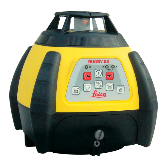
150 meters (500 feet) with a receiver. Simplicity The Rugby 55 is designed to be versatile, easy to operate and having features that serve both the interior and general construction contractor well. A bright,... - Page 6 Window assembly and rotating head b) Membrane switch panel c) Battery door and locking knob d) Charge port with LED (rechargeable models) e) Carrying handle (on back) 5/8”-11 mounting holes (on back and bottom) g) Positioning guides Description of the System Rugby 55...
- Page 7 Rugby 55 Membrane Switch Panel a) Low Battery LED b) Left / Right Positioning Buttons c) Scanning Button d) Head Speed Button (rps) e) X/Y Axis Level Indication LED’s Power Button g) CW / CCW Arrow Buttons Description of the System...
- Page 8 Case Component Locator, Interior Case a) Wall mount bracket b) Spare battery holder c) Alkaline batteries d) Remote control e) Ceiling grid targets User manual g) Receiver h) Rugby 55 Accessories compartment Description of the System Rugby 55...
- Page 9 Case Component Locator, Standard Case a) User manual b) Accessories and second receiver c) Spare batteries, D-cells d) Spare battery pack, NiMH e) Receiver Rugby Description of the System Rugby 55...
-
Page 10: Basic Operation
Basic Operation Topic Page In this chapter Introduction ................2-2 The LED Indicators ..............2-3 The Switch Buttons .............2-4 Special Features ..............2-6 Manual Mode with cross axis self-leveling ......2-9 The Elevation Alert (H.I.) Function ........2-12 Basic Operation Rugby 55... -
Page 11: Introduction
This manual contains operating and set-up procedures for common applica- tions. Its purpose is to describe the features of the Rugby 55 and how it oper- ates. This manual is not intended to describe specific applications. Contact Leica Geosystems or your distributor for information specific to your jobsite requirements. -
Page 12: The Led Indicators
Low Battery Indicator (b) When the LED is off, the battery is still good. When it is flashing slowly the battery is getting low. When the LED begins to flash rapidly it is time to change the batteries. Basic Operation Rugby 55... -
Page 13: The Switch Buttons
Press again to change both axes to manual mode • with no self-leveling • Press again to change back to full automatic mode. Note the changes in the LED indicators in these manual modes. The red LED indicates that the axis is in manual mode. Basic Operation Rugby 55... - Page 14 Press to rotate the stationary and scanning beam in a CW or CCW motion Manual Mode, Slope and Layout Buttons • Press to tilt the axis that is set to manual mode • In the laydown position, press to align the rotating and 90° split beam Basic Operation Rugby 55...
-
Page 15: Special Features
“downward” position to allow the user to align the Rugby over a reference point on the floor. Changing to 0-rps, positions the beam in the plumb down position. Basic Operation Rugby 55... - Page 16 • Scan Memory means that you can switch to rotational or stationary mode and the scan will return to the previous posi- tion wheh scanning motion is again chosen. Basic Operation Rugby 55...
- Page 17 Sleep Mode • Press both the Up and Down buttons simultaneously on the Remote to put the Rugby 55 into Sleep Mode. • During Sleep Mode all functions are disabled. • The Low battery indicator will flash once every ten seconds to indicate that the unit is in sleep mode.
-
Page 18: Manual Mode With Cross Axis Self-Leveling
The X-axis LED will blink green until level. When the Y-axis is in manual mode, the Y-axis can be sloped as illustrated here. The X and Y axes are marked on the top of the Rugby. Basic Operation Rugby 55... - Page 19 The Y-axis LED will blink green until level. H.I. When the X-axis is in manual mode, the X-axis can be sloped as illustrated here. The X and Y axes are marked on the top of the Rugby. Basic Operation Rugby 55 2-10...
- Page 20 The Y-axis LED will be red. H.I. When both the X and Y axes are in manual mode, both axes can be sloped as illustrated here. The X and Y axes are marked on the top of the Rugby. Basic Operation Rugby 55 2-11...
-
Page 21: The Elevation Alert (H.i.) Function
To stop the alert turn Rugby off and on again. Check the height of the instrument before beginning to work again. The elevation alert feature of the Rugby 55 is normally OFF when shipped. It can be enabled to turn on automatically every time the Rugby is turned on by using a special procedure found in the Troubleshooting section. -
Page 22: Accessories
Accessories Topic Page In this chapter The IR Remote Control ............3-2 The Wall Mount ..............3-4 The Ceiling Grid Target ............3-5 The Batter Board Clamp ............3-6 Accessories Rugby 55... -
Page 23: The Ir Remote Control
90° split beam. c) Up and Down Arrow Buttons Press to tilt the X-axis when it is manual mode. d) Auto/Manual Button Press to change desired axis to manual mode. Accessories Rugby 55... - Page 24 The battery can only be accessed by removing the four screws and the back cover of the remote. Care should be taken when re- assembling the cover to ensure the o-ring seal is properly in place. Accessories Rugby 55...
-
Page 25: The Wall Mount
Rugby in the laying down position mounted on a tripod. The Rugby 55 has also a 5/8”-11 mounting hole in the side of the housing to allow the laser to be attached directly to a tripod or batter board clamp in the laying down position. -
Page 26: The Ceiling Grid Target
The ceiling grid can then be adjusted until the beam is hitting the center line of the target. • A small bracket on the back of the target allows the target to be set up over a control point for layout alignment (a). Accessories Rugby 55... -
Page 27: The Batter Board Clamp
The rotating beam and top plumb beam form a 90° reference for setting the form. • Using the remote or the buttons on the Rugby, align either of the beams to a second reference point. The second beam will be your 90° reference. Accessories Rugby 55... -
Page 28: Applications
Applications Topic Page In this chapter Installing Ceiling Grid............4-2 Using the Rugby in the Laying Down Position ....4-3 Using the Rugby with a Receiver.........4-4 More Applications ...............4-5 Applications Rugby 55... -
Page 29: Installing Ceiling Grid
Attach the magnetic target to the ceiling grid and adjust the height of the grid until the rotating or scanning beam is striking the center of the target. Applications Rugby 55... -
Page 30: Using The Rugby In The Laying Down Position
• Once aligned, the split beam and rotating beams can be used to locate 90° angles for layout. The rotating beam also creates a vertical plane for transferring points from the floor to the ceiling. Applications Rugby 55... -
Page 31: Using The Rugby With A Receiver
Attach the receiver to a grade rod or stick. Position the rod over a control point and adjust the height of the receiver until it is centered on the laser beam. The receiver’s bandwidth and audio volume can be adjusted using the buttons on the receiver. Applications Rugby 55... -
Page 32: More Applications
• Sloped ceilings Exterior applications • Setting elevation of forms and footings • Squaring of forms • Checking elevations and benchmarks • Landscaping • Drainage and septic systems • Fences and retaining walls • Decks and patios Applications Rugby 55... -
Page 33: Batteries
Replacing the Alkaline Batteries .........5-3 Replacing the NiMH Batteries ..........5-4 Charging the NiMH Batteries..........5-5 The Rugby 55 can be purchased with either alkaline batteries or a rechargeable NiMH battery pack. The following information is appropriate only to the model you have purchased. -
Page 34: Operating Principles
+10°C to +20°C/+50°F to +68°F if possible. • It is normal for the battery to become warm during charging. Using the chargers recommended by Leica Geosystems, it is not possible to charge the battery if the temperature is too high. Operation/Discharging •... -
Page 35: Replacing The Alkaline Batteries
Install two fresh batteries. Ensure they are installed correctly by noting the battery symbols (c) on the top of the battery door. • Reinstall the battery door and tighten the silver screw securely to ensure a good seal. Batteries Rugby 55... -
Page 36: Replacing The Nimh Batteries
• To remove the rechargeable pack, loosen the silver knob (a) and remove the pack (b). • Reinstall the battery pack and tighten the silver screw securely to ensure a good seal. Batteries Rugby 55... -
Page 37: Charging The Nimh Batteries
The small LED (d) next to the charge jack will turn on indicating that the Rugby is charging. The LED will blink when a full charge has been reached. • The batteries will reach a full charge in approxi- mately eight hours if completely drained. Batteries Rugby 55... -
Page 38: Accuracy Adjustment
Do not enter this mode or attempt adjustment unless you plan to change the accuracy. Accuracy adjustment should only be performed by a qualified indi- vidual that understands basic adjustment principles. This procedure is easier when performed with two people, on a relatively flat surface. Accuracy Adjustment Rugby 55... - Page 39 (approximately one minute after the unit begins to rotate), then mark the position of the beam (Position 1). • Rotate the laser 180°, allow it to self-level and mark the opposite side of the first axis (Position 2). Accuracy Adjustment Rugby 55...
- Page 40 Rotate the laser 180°, allow it to self-level and mark the opposite side of the first axis (Position 4). The Rugby is within its accuracy specification if the four marks are within ± 3/32” (± 2.6 mm) from the center. Accuracy Adjustment Rugby 55...
- Page 41 • Hang a plumb line on the wall. • Move the Rugby until the vertical, rotating beam is aligned to the plumb line. • If the rotating beam is not plumb, adjustment is necessary. Accuracy Adjustment Rugby 55...
- Page 42 Adjusting Level Accuracy The checking and adjustment of the accuracy of the Rugby 55 requires a two- step process. • Checking and adjusting the horizontal plane - The X and Y axes. • Checking and adjusting the vertical plane - The Z axis.
- Page 43 1. The X and Y-axis LED’s will flash alternately three times. 2. The X-axis LED will flash three times, then flash slowly until level. 3. The Y-axis LED will be off. 4. When leveled, the X-axis LED will turn ON (not blinking). Accuracy Adjustment Rugby 55...
- Page 44 1. The X and Y-axis LED’s shall flash alternately three times each. 2. The Y-axis LED will flash three times, then flash slowly until level. 3. The X-axis LED will be off. 4. When leveled, the Y-axis LED will turn ON (not blinking). Accuracy Adjustment Rugby 55...
- Page 45 The X-axis and Y- axis LED’s shall flash alternately three times each, then the unit shall turn off. Pressing the POWER button at any time while in adjustment mode shall exit the mode without saving any changes. Accuracy Adjustment Rugby 55...
- Page 46 1. The X and Y-axis LED’s will flash alternately three times. 2. The X-axis LED will flash three times, then flash slowly until level. 3. The Y-axis LED will be off. 4. When leveled, the X-axis LED will turn ON (not blinking). Accuracy Adjustment Rugby 55...
- Page 47 Y-axis LED’s shall flash alternately three times each, then the unit shall turn off. Pressing the POWER button at any time while in adjustment mode shall exit the mode without saving any changes. Accuracy Adjustment Rugby 55 6-10...
-
Page 48: Troubleshooting
H.I. Servo Limit All three LED’s flashing slowly in a counter-clockwise motion - The Rugby is tipped too far to reach a level position. • Relevel the Rugby within its wide five degree self- H.I. leveling range. Troubleshooting Rugby 55... - Page 49 Dirt may be reducing the output of the laser. is reduced • Clean the windows of the Rugby and the receiver to improve performance. • If not the windows, the Rugby must be returned to an authorized service center for service. Troubleshooting Rugby 55...
- Page 50 The unit will beep once to indicate the change. The Rugby does not The Rugby 55 is designed to always turn on in auto- turn on in automatic matic mode unless specifically disabled by the user. mode.
- Page 51 The unit will beep once to indicate the change. • With automatic mode at start up disabled, the Rugby will turn on with the last mode used when turned off. Troubleshooting Rugby 55...
-
Page 52: Care And Transport
Care and Transport Topic Page In this chapter Transport ................8-2 Storage ................8-3 Cleaning and Drying ............8-4 Care and Transport Rugby 55... - Page 53 Always carry the product in its transport container and secure it. Shipping When transporting the product by rail, air or sea, always use the complete original Leica Geosystems packaging, transport container and cardboard box, or its equivalent, to protect against shock and vibration. Shipping, transport...
- Page 54 Remove batteries from the product and the charger before storing. • After storage recharge batteries before using. • Protect batteries from damp and wetness. Wet or damp batteries must be dried before storing or use. Care and Transport Rugby 55...
-
Page 55: Cleaning And Drying
40°C / 108°F and clean them. • Do not repack until everything is completely dry. Cables and Plugs • Keep plugs clean and dry. • Blow away any dirt lodged in the plugs of the connecting cables. Care and Transport Rugby 55... -
Page 56: Safety Directions
Safety Directions Topic Page In this chapter General................9-2 Intended Use...............9-3 Limits of Use ...............9-5 Responsibilities ..............9-6 International Warranty............9-7 Hazards of Use..............9-8 Laser Classification ............9-14 Electromagnetic Compatibility (EMC) ........9-23 FCC Statement, Applicable in U.S........9-25 Safety Directions Rugby 55... -
Page 57: General
The following directions should enable the person responsible for the product, and the person who actually uses the equipment, to anticipate and avoid oper- ational hazards. The person responsible for the product must ensure that all users understand these directions and adhere to them. Safety Directions Rugby 55... -
Page 58: Intended Use
• Use of products with obviously recognizable damages or defects. • Use with accessories from other manufacturers without the prior explicit approval of Leica Geosystems. • Inadequate safeguards at the construction site, for example when using on or near roads. - Page 59 Adverse use can lead to injury, malfunction and damage. It is the task of the person responsible for the equipment to inform the user about hazards and how to counteract them. The product is not to be operated until the user has been instructed on how to work with it. Safety Directions Rugby 55...
-
Page 60: Limits Of Use
Danger Local safety authorities and safety experts must be contacted before working in hazardous areas, or in close proximity to electrical installations or similar situations by the person in charge of the product. Safety Directions Rugby 55... -
Page 61: Responsibilities
Manufacturer of the Manufacturer of the product Leica Geosystems AG, CH-9435 Heerbrugg, here- product inafter referred to as Leica Geosystems, is responsible for supplying the product, including the user manual and original accessories, in a completely safe condition. Manufacturers of... -
Page 62: International Warranty
International Warranty International The International Warranty can be downloaded from the Leica Geosystems AG Warranty home page at http://www.leica-geosystems.com/internationalwarranty or received from your Leica Geosystems dealer. Safety Directions Rugby 55... -
Page 63: Hazards Of Use
Precautions: Periodically carry out test measurements and perform the field adjustments indicated in the user manual, particularly after the product has been subjected to abnormal use and before and after important measurements. Safety Directions Rugby 55... - Page 64 Warning By working in a thunderstorm you are at risk from lightning. Precautions: Do not carry out field work during thunderstorms. Safety Directions Rugby 55...
- Page 65 Precautions: When setting-up the product, make sure that the accessories are correctly adapted, fitted, secured, and locked in position. Avoid subjecting the product to mechanical stress. Safety Directions Rugby 55 9-10...
- Page 66 Before transpor- tation or shipping contact your local passenger or freight transport company. Warning Using a battery charger not recommended by Leica Geosystems can destroy the batteries. This can cause fire or explosions. Precautions: Only use chargers recommended by Leica Geosystems to charge the batteries.
- Page 67 Precautions: Make sure that the battery terminals do not come into contact with metallic objects. Safety Directions Rugby 55 9-12...
- Page 68 Product specific treatment and waste management information can be down- loaded from the Leica Geosystems home page at http://www.leica-geosys- tems.com/treatment or received from your Leica Geosystems dealer. Warning Only Leica Geosystems authorized service workshops are entitled to repair these products. Safety Directions Rugby 55...
-
Page 69: Laser Classification
Warning There are two versions of the Rugby 55. These two models represent varia- tions in laser output. All other functions and features are the same on both models. Review the information below for the unit you have purchased. The products are clearly identified by article number, serial number and safety label. - Page 70 Do not aim at areas that are essentially reflective, such as a mirror, or which could emit unwanted reflections. Do not look through or beside the optical sight at prisms or reflecting objects when the laser is switched on. Safety Directions Rugby 55 9-15...
- Page 71 Precautions should be taken to ensure that the laser beam is not inten- tionally directed at mirror like (specular) surfaces (e.g. mirrors, metal surfaces, windows). But, more importantly, at flat or concave mirror-like surfaces. Safety Directions Rugby 55 9-16...
- Page 72 Labeling, Laser Clas- sification IIIa Type: R55-A Art.No.: 754835 Power: 3.0V / 1.5A Leica Geosystems AG CH-9435 Heerbrugg Manufactured: S.No.: Made in Singapore This laser product complies with 21CFR 1040 as applicable. This device complies with part 15 of the FCC Rules.
- Page 73 Maximum average radiant power 0.5 mW +/- 5% Maximum peak radiant power: 4.75 mW +/- 5% Pulse duration 5.6, 2.2 and 1.1 ms Pulse repetition frequency: 2, 5 and 10 rps Beam divergence < 1.5 mrad Safety Directions Rugby 55 9-18...
- Page 74 (2001-08) resp. EN 60825-1:1994 + A11:1996 + A2:2001, within the hazard distance*); pay particular attention to Section Three “Users Guide”. Following is an interpretation of the main points in the relevant section of the standard quoted. Safety Directions Rugby 55 9-19...
- Page 75 *) The hazard distance is the distance from the laser at which the beam irra- diance or radiant exposure equals the maximum permissible value to which personnel may be exposed without being exposed to a health risk. Safety Directions Rugby 55 9-20...
- Page 76 For products with an integrated distancer of laser class 3R this hazard distance is 103 m / 337 feet. At this distance, the laser beam rates as Class 1, that means direct intrabeam viewing is not hazardous. Safety Directions Rugby 55 9-21...
- Page 77 Laser λ = 620 - 690 nm Aperture Type: R55-R Art.No.: 753671 Power: 3.0V / 1.5A Leica Geosystems AG CH-9435 Heerbrugg Manufactured: S.No.: Made in Singapore Complies with 21 CFR 1040.10 and 1040.11 except for deviations pursuant to Laser Notice No.50, dated July 26, 2001.
-
Page 78: Electromagnetic Compatibility (Emc)
Warning Electromagnetic radiation can cause disturbances in other equipment. Although the product meets the strict regulations and standards which are in force in this respect, Leica Geosystems cannot completely exclude the possi- bility that other equipment may be disturbed. Caution... - Page 79 Disturbances caused by electromagnetic radiation can result in erroneous measurements. Although the product meets the strict regulations and standards whichin this respect, Leica Geosystems cannot completely exclude the possibility product may be disturbed by very intense electromagnetic radiation, near radio trans- mitters, two-way radios or diesel generators.
-
Page 80: Fcc Statement, Applicable In U.s
Increase the separation between the equipment and the receiver. • Connect the equipment into an outlet on a circuit different from that to which the receiver is connected. • Consult the dealer or an experienced radio/TV technician for help. Safety Directions Rugby 55 9-25... - Page 81 Warning Changes or modifications not expressly approved by Leica Geosystems for compliance could void the user's authority to operate the equipment. a) Laser class IIIa: Laser class 3R: Labeling Rugby 55 Type: R55-A Type: R55-R Art.No.: 754835 Art.No.: 753671 Power: 3.0V / 1.5A Power: 3.0V / 1.5A...
-
Page 82: Technical Data
Technical Data Rugby 55 Operating Range (rotating beam) 300 m (1000 ft) Diameter, with receiver Operating Range (plumb beam) up to 60 m (200 ft) Self-leveling Accuracy* ±2.6 mm at 30 m (±3/32” at 100 ft) Self-leveling Range ± 5°... - Page 83 NiMH Input voltage 100-240 VAC, 55-60 Hz Charger/Adapter Output voltage 7.5 VDC Output current 1.0 A Polarity Shaft - neg, Tip - pos Accuracy is defined at 25°C Battery life is dependent upon environmental conditions Technical Data Rugby 55 10-2...
-
Page 84: Index
Rugby 55 Index Overview ..........5-2 Accessories Removing ..........3-6 Batter board clamp .........3-6 Replacing the Alkaline Batteries ....5-3 Ceiling grid target ........3-5 Replacing the NiMH Batteries ....5-4 Remote control ........3-2 Beam Down (function) ........2-6 Wall mount bracket .........3-4 Accuracy Care and Transport ......... - Page 85 Wallmount bracket (accessory) ....... 3-4 Membrane switch buttons ......2-4 Warranty ............9-7 Receivers (use with) ........4-4 Remote control (accessory) ......3-2 Safety Electromagnetic Compatibility (EMC) ..9-23 FCC Statement ........9-25 Intended Use ..........9-3 Labeling ..........9-17 Laser Classification .......9-14 Limits of Use ...........9-5 Responsibilities ........9-6 Rugby 55...
- Page 86 International Standards of Quality Management and Quality Systems (ISO standard 9001) and Environmen- tal Management Systems (ISO standard 14001). Ask your local Leica Geosystems dealer for more information about our TQM pro- gram. Leica Geosystems AG Heinrich-Wild-Strasse...
Need help?
Do you have a question about the Rugby 55 and is the answer not in the manual?
Questions and answers