Leica TPS1200+ User Manual
Hide thumbs
Also See for TPS1200+:
- Field manual (210 pages) ,
- Field manual (258 pages) ,
- Reference manual (207 pages)
Table of Contents
Advertisement
Quick Links
Advertisement
Table of Contents

Subscribe to Our Youtube Channel
Related Manuals for Leica TPS1200+


Summary of Contents for Leica TPS1200+
- Page 1 Leica TPS1200+ User Manual Version 7.0 English...
- Page 2 The type and the serial number of your product are indicated on the type plate. identification Enter the type and serial number in your manual and always refer to this information when you need to contact your agency or Leica Geosystems authorized service workshop. Type: _______________ Serial No.:...
- Page 3 Symbols The symbols used in this manual have the following meanings: Type Description Danger Indicates an imminently hazardous situation which, if not avoided, will result in death or serious injury. Warning Indicates a potentially hazardous situation or an unintended use which, if not avoided, could result in death or serious injury.
- Page 4 Introduction TPS1200+ Validity of this Description manual General This manual applies to all TPS1200+ Series instruments. Where there are differences between the various models they are clearly described. Telescope • Measuring with IR mode: When measuring distances to a reflector with EDM mode "IR", the telescope uses a wide visible red laser beam, which emerges coaxially from the tele- scope's objective.
- Page 5 Reference program functions. Included are detailed descriptions Manual of special software/hardware settings and soft- ware/hardware functions intended for technical specialists. Refer to the following resources for all TPS1200+ documentation and software • the Leica SmartWorx DVD • http://www.leica-geosystems.com/downloads Introduction TPS1200+...
-
Page 6: Table Of Contents
Table of Contents TPS1200+ Table of Contents In this manual Chapter Page Description of the System System Components System Concept 1.2.1 Software Concept 1.2.2 Data Storage and Data Conversion Concept 1.2.3 Power Concept Container Contents Instrument Components User Interface Keyboard Screen Operating Principles Icons... - Page 7 Operation Instrument Setup Autodetect Behaviour Instrument Setup as SmartStation 3.3.1 SmartStation Setup 3.3.2 LED Indicators on SmartAntenna 3.3.3 Working with the Clip-On-Housings for Devices 3.3.4 LED Indicators on Clip-On-Housings Instrument Setup for Remote Control 3.4.1 Remote Control Setup 3.4.2 LED Indicators on RadioHandle Battery 3.5.1 Operating Principles...
- Page 8 Table of Contents TPS1200+ Check & Adjust Overview Preparation Combined Adjustment (l, t, i, c and ATR) Tilting Axis Adjustment (a) Adjusting the Circular Level of the Instrument and Tribrach Adjusting the Circular Level of the Prism Pole Inspecting the Laser Plummet of the Instrument Servicing the Tripod Care and Transport Transport...
- Page 9 Safety Directions General Introduction Intended Use Limits of Use Responsibilities Hazards of Use Laser Classification 6.6.1 General 6.6.2 Distancer, Measurements with Reflectors (IR mode) 6.6.3 Distancer, Measurements without Reflectors (RL mode) 6.6.4 Automatic Target Recognition ATR 6.6.5 PowerSearch PS 6.6.6 Electronic Guide Light EGL 6.6.7 Laser Plummet...
- Page 10 Table of Contents TPS1200+ Technical Data Angle Measurement Distance Measurement with Reflectors (IR mode) Distance Measurement without Reflectors (RL mode) Distance Measurement - Long Range (LO mode) Automatic Target Recognition ATR PowerSearch PS SmartStation 7.7.1 SmartStation Accuracy 7.7.2 SmartStation Dimensions 7.7.3 SmartAntenna Technical Data Conformity to National Regulations...
- Page 11 International Limited Warranty, Software License Agreement Index Table of Contents TPS1200+...
-
Page 12: Description Of The System
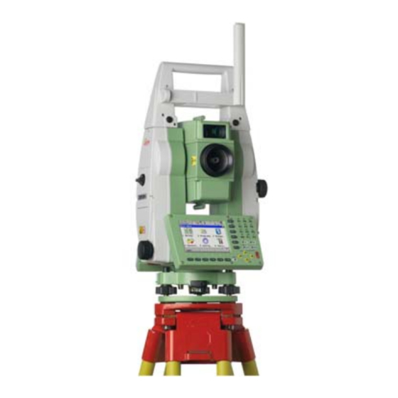
Description of the System TPS1200+ Description of the System System Components Main components RX1200 TPS1200+ TPS12_198 Component Description TPS1200+ • an instrument for measuring, calculating and capturing data. • comprised of various models with a range of accuracy classes. • integrated with an add-on GNSS system to form SmartStation. - Page 13 Global Navigation Satellite System (generic term for satellite based navigation systems like GPS, GLONASS, Galileo, Compass, SBAS) Remote Control Surveying LEICA Geo Office Electronic Distance Measurement EDM refers to the laser distancer incorporated into the instru- ment which enables distance measurement.
- Page 14 Description of the System TPS1200+ Term Description Three measuring modes are available: • IR mode. This mode refers to the ability to measure distances to prisms. • RL mode. This mode refers to the ability to measure distances without prisms. •...
- Page 15 Term Description ATR refers to the instrument sensor which enables the automatic fine pointing to a prism. Automated Instruments fitted with ATR are referred to as Automated. Three automation modes are available with ATR: • None: no ATR - no automation and no tracking. •...
- Page 16 Description of the System TPS1200+ Term Description The GNSS principles and functionality of SmartStation derive from the principles and functionality of GPS1200+ instruments. SmartAntenna SmartAntenna with integrated Bluetooth is a component of SmartStation. It can also be used independently on a pole, with a GNSS receiver and remote controller.
- Page 17 TCRA1200+ Additional components: Reflectorless EDM, Automated, Motor- ised. TCRP1200+ Additional components: Reflectorless EDM, Automated, Motor- ised, PowerSearch. LEICA Geo Office • LGO supports GPS1200+ and TPS1200+ instruments. It also supports all other Leica TPS instruments. ® • LGO is based on a graphical user interface with standard Windows operating procedures.
- Page 18 Description of the System TPS1200+ Functionality Description Extended Includes Coordinate transformations, GPS and GLONASS post Functionality processing, Level data processing, Network adjustment, GIS and CAD Export. ® ® • Supported operating systems: Windows XP, Windows 2000. • Refer to the online help of LGO for additional information.
-
Page 19: System Concept
System Concept 1.2.1 Software Concept Description TPS1200+ instruments use the same software concept. Software type Software type Description System This software comprises the central functions of the instrument. software It is also referred to as firmware. The programs Survey and Setup are integrated into the firmware and cannot be deleted. - Page 20 GeoC++ development kit. Information on the programs GeoC++ development environment is available on request from a Leica Geosystems representative. Software upload All instrument software is stored in the System RAM of the instrument. The software can be uploaded onto the instrument using the following methods: •...
-
Page 21: Data Storage And Data Conversion Concept
Flash card can be inserted and removed. Available capacity: 256 MB. Whilst other CompactFlash cards may be used, Leica recommends Leica CompactFlash cards and cannot be held responsible for data loss or any other error that may occur when using a non-Leica card. - Page 22 Data can be exported from a job in a wide range of ASCII formats. The export format is defined in Format Manager which is a PC tool in LEICA Geo Office. Refer to the online help of LGO for information on creating format files.
-
Page 23: Power Concept
1.2.3 Power Concept General Use the Leica Geosystems batteries, chargers and accessories or accessories recommended by Leica Geosystems to ensure the correct functionality of the instru- ment. Power options Instrument Power for the instrument can be supplied either internally or externally. An external battery is connected to the instrument using a LEMO cable. -
Page 24: Container Contents
Description of the System TPS1200+ Container Contents Container for instrument and delivered accessories part 1 of 2 a) GHT196 Tribrach bracket for height meter b) Data transfer cable c) GFZ3 or GOK6 diagonal eyepiece d) Counterweight for diagonal eyepiece e) Instrument with tribrach and standard handle or RadioHandle Protective cover for instrument and sunshade for objective lens... - Page 25 Container for instrument and delivered accessories part 2 of 2 a) Pocket knife b) Spare stylus c) User manuals d) 2 x CompactFlash cards and covers e) Allen key GKL221 Battery charger g) Car adapter power plug for battery charger (stored under battery charger) TPS12_010b Description of the System TPS1200+...
- Page 26 Description of the System TPS1200+ Container for System 1200 a) GAD33 Arm 15cm components b) ATX SmartAntenna part 1 of 2 c) Cables d) GHT52 Clamp e) GAD31 Adapter Radio antennas g) GAD104 SmartAntenna Adapter h) GFU Radio modem Mini Prism spike GEB221 Battery k) GRZ101 Mini prism and GAD103 Adapter...
- Page 27 Container for System 1200 components part 2 of 2 a) Manuals b) GHT57 Bracket c) CompactFlash card and cover d) GRZ4 / GRZ122 Prism e) Spare stylus Software DVD g) GEB211 Battery h) GHT56 Holder TNC L-adapter GEB221 Batteries k) RX1250 Controller GHT39 Holding plate SYS12_002 Description of the System...
-
Page 28: Instrument Components
Description of the System TPS1200+ Instrument Components Instrument a b c d e f components part 1 of 2 a) Carry handle b) Optical sight c) Telescope, integrating EDM, ATR, EGL, PS d) EGL flashing diode - yellow and red e) PowerSearch, transmitter PowerSearch, receiver g) Coaxial optics for angle and distance meas-... - Page 29 Instrument components part 2 of 2 k) Vertical drive Focusing ring m) Battery compartment n) Stylus for touch screen o) Screen p) Circular level q) Tribrach footscrew Interchangeable eyepiece s) Keyboard TPS12_001b Description of the System TPS1200+...
- Page 30 Description of the System TPS1200+ Instrument components for SmartStation a) SmartAntenna b) Antenna for communication device c) Clip-on-housing for communication device d) SmartAntenna Adapter e) Communication side cover TPS12_197...
- Page 31 Instrument components for a) RadioHandle b) Communication side cover TPS12_199 Description of the System TPS1200+...
-
Page 32: User Interface
User Interface TPS1200+ User Interface Keyboard Keyboard / $ % _ @ & * ? ! USER PROG PgUp SHIFT PgDn TPS12_070... - Page 33 a) Hot keys F7-F12 b) Alphanumeric keys e) Arrow keys c) CE, ESC, USER, PROG SHIFT d) ENTER g) Function keys F1-F6 Keys Description Hot keys F7-F12 • User definable keys to execute commands or access chosen screens. Alphanumeric keys •...
- Page 34 User Interface TPS1200+ Description ENTER • Selects the highlighted line and leads to the next logical dialog/menu. • Starts the edit mode for edit fields. • Opens a list box. SHIFT • Changes between the first and the second level of func- tion keys.
- Page 35 Keys Description SHIFT Pages up. SHIFT Pages down. User Interface TPS1200+...
-
Page 36: Screen
User Interface TPS1200+ Screen Screen a) Time b) Caption c) Title d) Screen area e) Message line Icons g) ESC h) CAPS SHIFT icon Quick coding icon k) Softkeys TPS12_081 Elements of the Element Description screen Time The current local time is shown. Caption Shows location either in Main Menu, under PROG key or USER key. - Page 37 Element Description Message line Messages are shown for 10 s. Icons Shows current status information of the instrument. Refer to "2.4 Icons". Can be used with touch screen. Can be used with touch screen. Same functionality as the fixed key ESC. The last operation will be undone. CAPS The caps mode for upper case letters is active.The caps mode is activated and deactivated by pressing UPPER (F5) or...
-
Page 38: Operating Principles
User Interface TPS1200+ Operating Principles Keyboard and The user interface is operated either by the keyboard or by the touch screen with touch screen supplied stylus. The workflow is the same for keyboard and touch screen entry, the only difference lies in the way information is selected and entered. Turn instrument on Press and hold PROG for 2 s. - Page 39 Option Description Unlock To unlock the keyboard press and hold SHIFT for 3 s. The message ’Keyboard unlocked’ is momentarily displayed on the Message Line. Selecting Appearance Description from a menu To select an item from a menu, do one of the following: Move the focus to the item.
- Page 40 User Interface TPS1200+ Selecting a page Appearance Description To select a page in a screen, do one of the following: PAGE (F6). Tap on the page tab with the stylus. Edit an entire value Appearance Description in input fields 1. Highlight the field. 2.
- Page 41 Appearance Description 2. For the keyboard: ENTER. The edit mode is acti- vated where additional functions like insert and overwrite are available. 3. For the touch screen: Highlight the characters to be changed. 4. Type numeric and/or alphanumeric characters. 5. ENTER or tap outside of the field. Access special Step Description...
- Page 42 User Interface TPS1200+ Step Description Repeat step 4. and 5. for entering more special characters of the same character set. ENTER. Appearance and Choicelists have various appearances. selection from a Closed choicelist choicelist Appearance Description Selection Triangles on the right indi- Use the arrow keys cate further available change through the list or...
- Page 43 Simple listbox Appearance Description Selection • Choicelist shows • Highlight the item and items to select. ENTER. • A search field is • To exit without shown if necessary. changes ESC, tap or outside the simple • A scroll bar is shown if listbox.
- Page 44 User Interface TPS1200+ Listbox dialog Appearance Description Selection • Choicelist fills the • Highlight the item and whole screen. CONT (F1). • A search field is • To exit without shown. changes press ESC or tap . • A scroll bar is shown if necessary.
-
Page 45: Icons
Icons Description The screen icons display the current status information of the instrument. Position of the b c d g h i a) ATR/LOCK/PS icons on the screen b) Reflector c) EDM d) Compensator/face I&II e) RCS Bluetooth g) Line/area h) CompactFlash card/internal memory Battery SHIFT... - Page 46 User Interface TPS1200+ a) GNSS position status a b c d e f g h i b) Number of visible satellites c) Contributing satellites d) Real-time device and real-time status, Internet online status e) Position mode Bluetooth g) Line/area h) CompactFlash card/internal memory Battery SHIFT k) Quick coding...
- Page 47 Icon Description Compensator/face I&II Compensator off, out of range or face I&II icon is displayed. RCS settings are displayed. GPS specific icons Icon Description GNSS Position status Displays the status of the current position. As soon as this icon becomes visible the receiver is in a stage where practical operation can commence.
- Page 48 User Interface TPS1200+ Icon Description The number of contributing satellites can differ from the number of visible satellites. This may be either because satellites cannot be viewed or the observations to these satellites are considered to be too noisy to be used in the position solution.
- Page 49 Icon Description CompactFlash The status of the CompactFlash card and internal card/internal memory memory if fitted are displayed. • For the CompactFlash card, the capacity of used space is shown in seven levels. • For the internal memory if fitted, the capacity of used memory is shown in nine levels.
-
Page 50: Operation
Operation TPS1200+ Operation Instrument Setup Description This topic describes an instrument setup over a marked ground point using the laser plummet. It is always possible to set up the instrument without the need for a marked ground point. Important features: •... - Page 51 Setup step-by-step SHIFT TPS12_019 Step Description Shield the instrument from direct sunlight and avoid uneven temperatures around the instrument. Extend the tripod legs to allow for a comfortable working posture. Position the tripod over the marked ground point, centring it as well as possible. Fasten the tribrach and instrument onto the tripod.
- Page 52 Operation TPS1200+ Step Description Turn on the instrument by pressing PROG for 2 s. Press SHIFT (F12) to access STATUS Level & Laser Plummet, activating the laser plummet. Move the tripod legs (1) and use the tribrach footscrews (6) to centre the plummet (4) over the ground point.
-
Page 53: Autodetect Behaviour
Autodetect Behaviour Description • The instrument incorporates an autodetect behaviour and automatically detects the following devices: • SmartAntenna • RadioHandle • radios/modems in clip-on-housings • Whenever a device is attached, the instrument responds with two short beeps. • Whenever a device is removed, the instrument responds with one long beep. SmartAntenna •... - Page 54 Operation TPS1200+ • In addition to the autodetect behaviour, SmartAntenna can also be manually turned on/off using the ON/OFF button located on the underside. This action overrides all automatic settings but is only possible when SmartAntenna is fitted with an internal battery. •...
-
Page 55: Instrument Setup As Smartstation
Instrument Setup as SmartStation 3.3.1 SmartStation Setup Setup step-by-step Step Description Refer to "3.5 Battery" to change the internal battery of the SmartAntenna. Refer to "3.1 Instrument Setup" for the initial instrument setup onto a tripod. Remove the instrument carry handle by simultaneously pressing and holding-in the four push buttons. - Page 56 Operation TPS1200+ Step Description A circular screw is located at one end of the clip-on-housing. Ensure that the circular screw is in the unlocked position. Turn it anticlockwise, as shown by the lock and arrow symbols on the screw. Slide the clip-on-housing into position underneath the SmartAntenna Adapter, such that the guide rails on the clip-on-housing and the guide rails on the SmartAntenna Adapter are aligned.
- Page 57 TPS12_195 Step Description Place the SmartAntenna Adapter with attached clip-on-housing onto the instrument by simultaneously pressing and holding-in the four push buttons. Ensure that the interface connection on the underside of the Smart- Antenna Adapter is on the same side as the Communication side cover. Operation TPS1200+...
- Page 58 Operation TPS1200+ TPS12_209 Step Description Place the SmartAntenna onto the SmartAntenna Adapter by simultane- ously pressing and holding-in the two press clips. Ensure that the clip-on-contacts on the underside of the SmartAntenna are aligned to the clip-on-contacts of the SmartAntenna Adapter.
-
Page 59: Led Indicators On Smartantenna
3.3.2 LED Indicators on SmartAntenna LED Indicators Description SmartAntenna has Light Emitting Diode indicators. They indicate the basic antenna status. Diagram of LED Indicators Tracking LED Bluetooth LED Power LED TPS12_200 Operation TPS1200+... - Page 60 Operation TPS1200+ Description of LED Indicators IF the THEN no satellites are tracked. flashing green less than four satellites are tracked, a position is not yet available. green enough satellites are tracked to compute a position. SmartAntenna is initialising. green Bluetooth is in data mode and ready for connecting.
-
Page 61: Working With The Clip-On-Housings For Devices
3.3.3 Working with the Clip-On-Housings for Devices Devices fitting into Digital cellular phones fitting into a clip-on-housing a clip-on-housing Digital cellular phone Clip-on-housing Siemens MC75 GFU24 CDMA MultiTech MTMMC-C (US) GFU19, GFU26 CDMA MultiTech MTMMC-C (CAN) GFU25 Radios fitting into a clip-on-housing Radio Clip-on-housing Pacific Crest PDL, receive... - Page 62 Operation TPS1200+ Attach/detach a Attach a clip-on-housing clip-on-housing Refer to "3.3.1 SmartStation Setup" for detailed information. step-by-step Detach a clip-on-housing Step Description A circular screw is located at one end of the clip-on-housing. To unlock and release the clip-on-housing from the SmartAntenna Adapter turn the screw anticlockwise, as shown by the lock and arrow symbols on the screw.
- Page 63 Step Description Remove the SIM card screw from the housing. Using the pen, press the small button of the SIM card slot to eject the SIM card holder. Take the SIM card holder out off the housing. Put the SIM card into the SIM card holder, the chip facing up. Insert the SIM card holder into the SIM card slot, the chip facing the connectors inside the slot.
- Page 64 Operation TPS1200+ Step Description Insert the coin into the groove of the SIM card screw. Turn the coin anticlockwise to loosen the SIM card screw. Remove the SIM card screw from the housing. Using the pen, press the small button of the SIM card slot to eject the SIM card holder.
-
Page 65: Led Indicators On Clip-On-Housings
3.3.4 LED Indicators on Clip-On-Housings LED Indicators Description Each clip-on-housing for a radio or a digital cellular phone has Light Emitting Diode indicators. They indicate the basic device status. Diagram of the LED Indicators a) Power LED b) Signal strength LED a b c d c) Data transfer LED d) Warning LED,... - Page 66 Operation TPS1200+ Description of the LED Indicators IF the THEN Warning GFU14 with the device is in the configuration Satelline 3AS mode controlled from the PC via cable. Data any device data is not being transferred. transfer green or data is being transferred. flashing green Signal GFU19 (US),...
- Page 67 IF the THEN GFU24 with call is in progress. Siemens MC75 red: long flash, long no SIM card inserted, no PIN break entered or network search, user authentication or network login in progress. red: short flash, logged onto network, no call in long break progress.
- Page 68 Operation TPS1200+ IF the THEN GFU15 with red or the communication link, Data Pacific Crest flashing red Carrier Detection, is okay on the roving receiver. the DCD is not okay. GFU14 with red or the communication link, Data Satelline 3AS flashing red Carrier Detection, is okay on the roving receiver.
-
Page 69: Instrument Setup For Remote Control
Instrument Setup for Remote Control 3.4.1 Remote Control Setup Setup step-by-step TPS12_196 Step Description Refer to "3.1 Instrument Setup" for the initial instrument setup onto a tripod. Remove the instrument carry handle by simultaneously pressing and holding-in the four push buttons. Place the RadioHandle onto the instrument by simultaneously pressing and holding-in the four push buttons. - Page 70 Operation TPS1200+ Step Description Ensure that the interface connection on the underside of the RadioHandle is on the same side as the Communication side cover. Swing the RadioHandle antenna into an upright position. Refer to "RX1200 User Manual" for additional information.
-
Page 71: Led Indicators On Radiohandle
3.4.2 LED Indicators on RadioHandle LED Indicators Description The RadioHandle has Light Emitting Diode indicators. They indicate the basic RadioHandle status. Diagram of the LED Indicators a b c d a) Power LED b) Link LED c) Data Transfer LED d) Mode LED Operation TPS1200+... - Page 72 Operation TPS1200+ Description of the LED Indicators IF the THEN Power LED power is off. green power is on. Link LED no radio link to remote controller. radio link to remote controller. Data Transfer LED no data transfer to/from remote controller. green or data transfer to/from remote controller.
-
Page 73: Battery
+10°C to +20°C/+50°F to +68°F if possible. • It is normal for the battery to become warm during charging. Using the chargers recommended by Leica Geosystems, it is not possible to charge the battery if the temperature is too high. Operation... - Page 74 Operation TPS1200+ Operation/Discharging • The batteries can be operated from -20°C to +55°C/-4°F to +131°F. • Low operating temperatures reduce the capacity that can be drawn; very high operating temperatures reduce the service life of the battery.
-
Page 75: Instrument Battery
3.5.2 Instrument Battery Change battery step-by-step TPS12_011 Step Description Face the instrument so that the vertical drive screw is on the left. The battery compartment is now on the left side of the instrument. Turn the knob to the vertical position, opening the lid of the battery compartment. Pull out the battery housing. - Page 76 Operation TPS1200+ Step Description Place the battery into the battery housing, ensuring that the contacts are facing outward. Click the battery into position. Place the battery housing into the battery compartment. Push the battery housing in until it fits completely into the battery compartment. Turn the knob to lock the battery compartment.
-
Page 77: Smartantenna Battery
3.5.3 SmartAntenna Battery Change battery step-by-step TPS12_193 Step Description Turn SmartAntenna over to gain access to the battery compartment. Open the battery compartment by pushing the slide fastener in the direc- tion of the arrow with the open-lock symbol. Pull out the battery housing. The battery is attached to the housing. Hold the battery housing and pull the battery from the battery housing. - Page 78 Operation TPS1200+ Step Description A polarity of the battery is displayed inside the battery housing. This is a visual aid to assist in placing the battery correctly. Place the battery onto the battery housing, ensuring that the contacts are facing outward. Click the battery into position. Close the battery compartment by pushing the slide fastener in the direc- tion of the arrow with the close-lock symbol.
-
Page 79: Working With The Compactflash Card
Working with the CompactFlash Card • Keep the card dry. • Use it only within the specified temperature range. • Do not bend the card. • Protect the card from direct impacts. Failure to follow these instructions could result in data loss and/or permanent damage to the card. - Page 80 Operation TPS1200+ Step Description Face the instrument so that the vertical drive screw is on the left. The CompactFlash card compartment is now on the right side of the instru- ment. Turn the knob to the vertical position, opening the lid of the CompactFlash card compartment.
- Page 81 Step Description Main Menu: Tools...\Format Memory Device. TOOLS Format Memory Device <Memory Device: CF Card> <Format Method: Format Quick> Select the memory device to be formatted. By activating the format command all data will be lost. Make sure that all important data on the CompactFlash card has been backed up before formatting the card.
-
Page 82: Accessing Survey Application Program
Operation TPS1200+ Accessing Survey Application Program Access Select Main Menu: Survey. Press PROG. Highlight Survey. CONT (F1). SURVEY Survey Begin CONT (F1) To accept changes and access the subsequent screen. The chosen settings become active. CONF (F2) To access SURVEY Configuration. SETUP (F3) Opens SETUP Station Setup to set station and orientation. - Page 83 CSYS (F6) To select a different coordinate system. Not available for <Use Auto CrdSys: Yes> configured in CONFIGURE Additional Rover Settings. Description of fields Field Option Description <Job:> Choicelist The active job. All jobs from Main Menu: Manage...\Jobs can be selected. <Coord System:>...
- Page 84 Operation TPS1200+ Field Option Description Output Codes have already been stored in the selected <Job:>. If codes had been copied from a System RAM codelist, then the name of the codelist is displayed. If codes have not been copied from a System RAM codelist but typed in manually, then the name of the active job is displayed.
- Page 85 Field Option Description <Add. Constant:> Output Displays the additive constant stored with the chosen reflector. Next step CONT (F1) to access SURVEY Survey: Job Name, where measurements can be performed with ALL (F1) or DIST (F2) and/or REC (F3). Operation TPS1200+...
-
Page 86: Guidelines For Correct Results
Operation TPS1200+ Guidelines for Correct Results Very short distances may be measured reflectorless in IR mode to well reflecting targets. Note that the distances are corrected with the additive constant defined for the active reflector. Distance measurement TPS12_002 When measurements are being made using the red laser EDM, the results may be influenced by objects passing between the EDM and the intended target surface. - Page 87 ment may be made to the side of the vehicle. The result is the distance to the vehicle, not to the road surface. If using the red laser EDM for long range measurements to a prism, and an object passes within 30 m of the EDM as DIST (F2) or ALL (F1) is pressed, the distance measurement may be similarly effected due to the strength of the laser signal.
- Page 88 Operation TPS1200+ Vertical and horizontal angles and the distance are measured to the centre of the prism. The lock mode enables the instrument to follow a moving prism. As with all other instrument errors, the collimation error of the automatic target recog- nition must be redetermined periodically.
- Page 89 Operation TPS1200+...
-
Page 90: Check & Adjust
Check & Adjust Overview Description Leica instruments are manufactured, assembled and adjusted to the best possible quality. Quick temperature changes, shock or stress can cause deviations and decrease the instrument accuracy. It is therefore recommended to check and adjust the instrument from time to time. - Page 91 Every angle measured in the daily work is corrected automatically if the compensator and the Hz-corrections are activated in the instrument configuration. Select Main Menu: Config...\Instrument Settings...\Compensator to check the settings. View current The currently used adjustment errors can be viewed under Main Menu: adjustment errors Tools.../Check &...
- Page 92 Check & Adjust TPS1200+ During the manufacturing process, the instrument errors are carefully determined and set to zero. As mentioned above, these errors can change and it is highly recom- mended to redetermine them in the following situations: • Before the first use •...
- Page 93 Summary of errors Instrument error Effects Effects Elimination Automatically to be adjusted with two face corrected with electronically measurement proper adjust- ment c - Line of sight error a - Tilting axis error l - Compensator index error t - Compensator index error i - V-Index error ATR Collimation error Check &...
-
Page 94: Preparation
Check & Adjust TPS1200+ Preparation Before determining the instrument errors, the instrument has to be levelled- up using the electronic level. SHIFT F12 to access STATUS Level & Laser Plummet, Level page. The tribrach, the tripod and the underground should be very stable and secure from vibrations or other disturbances. - Page 95 corrected electronically. This means that the Hz- and V- angles are corrected twice: first by the determined ATR errors for Hz and V and then by the individual small devi- ations of the current pointing. Next step IF the task is to THEN adjust a combination of Refer to "4.3 Combined Adjustment (l, t, i, c and ATR)"...
-
Page 96: Combined Adjustment (L, T, I, C And Atr)
Check & Adjust TPS1200+ Combined Adjustment (l, t, i, c and ATR) Description The combined adjustment procedure determines the following instrument errors in one process: l, t Compensator longitudinal and transversal index errors Vertical index error, related to the standing axis Hz collimation error, also called line of sight error ATR Hz ATR zero point error for Hz angle - option... - Page 97 <ATR Adjust: On> Includes the determination of the ATR Hz and V adjustment errors if an ATR is available. It is recommended to use a clean Leica circular prism as target. Do not use a 360° prism. Aim the telescope accurately at a target at about 100 m distant.
- Page 98 Check & Adjust TPS1200+ Step Description MEAS (F1) to measure and to continue to the next screen. Motorised instruments change auto- matically to the other face. Non-motorised instruments guide to 180° the other face. The fine pointing has to be performed manually in both faces.
- Page 99 Step Description <No.of Meas:> Shows the number of runs executed. One run consists of a measurement in face I and face II. <σ l Comp:> and similar lines show the standard deviations of the deter- mined adjustment errors. The standard deviations can be calculated from the second run onwards.
- Page 100 Check & Adjust TPS1200+ Next step IF the results are THEN to be stored CONT (F1) overwrites the old adjustment errors with the new ones, if the Use status is set to Yes. to be determined REDO (F2) rejects all new determined adjustment errors and again repeats the whole procedure.
-
Page 101: Tilting Axis Adjustment (A)
Tilting Axis Adjustment (a) Description This adjustment procedure determines the following instrument error: Tilting axis error Determination of The following table explains the most common settings. tilting axis error Step Description step-by-step The Hz collimation error (c) has to be determined before starting this procedure. - Page 102 Check & Adjust TPS1200+ Step Description TOOLS Tilting-Axis Adjustment I Aim the telescope accurately at a target at about 100 m distance or less if not possible. The target must be positioned at least 27°/30 gon above or beneath the horizontal plane.
- Page 103 Step Description MEAS (F1) to measure and to continue to the next screen. Motorised instruments change auto- matically to the other face. Non-motorised instruments guide to 180° the other face. The fine pointing has to be performed manually in both faces. 180°...
- Page 104 Check & Adjust TPS1200+ Step Description TOOLS T-Axis Adjustment Accuracy <No.of Meas:> Shows the number of runs executed. One run consists of a measurement in face I and face II. <σ a T-axis:> shows the standard deviation of the determined tilting axis error.
- Page 105 Next step IF the results are THEN to be stored CONT (F1) overwrites the old tilting axis error with the new one. to be determined REDO (F2) rejects the new determined tilting axis error and again repeats the whole procedure. Refer to step 3. of paragraph "Determination of tilting axis error step-by-step".
-
Page 106: Adjusting The Circular Level Of The Instrument And Tribrach
Check & Adjust TPS1200+ Adjusting the Circular Level of the Instrument and Tribrach Adjusting the circular level step-by-step SHIFT TPS12_030 Step Description Place and secure the instrument into the tribrach and onto a tripod. Using the tribrach footscrews, level the instrument with the electronic level. - Page 107 Step Description Instrument: If it extends beyond the circle, use the supplied allen key to centre it with the adjustment screws. Turn the instrument by 200 gon (180°). Repeat the adjustment procedure if the circular level does not stay centered. Tribrach: If it extends beyond the circle, use the supplied allen key to centre it with the adjustment screws.
-
Page 108: Adjusting The Circular Level Of The Prism Pole
Check & Adjust TPS1200+ Adjusting the Circular Level of the Prism Pole Adjusting the Step Description circular level Suspend a plumb line. step-by-step Using a pole bipod, align the prism pole parallel to the plumb line. Check the position of the circular level on the prism pole. -
Page 109: Inspecting The Laser Plummet Of The Instrument
The laser plummet is located in the vertical axis of the instrument. Under normal conditions of use, the laser plummet does not need adjusting. If an adjustment is necessary due to external influences, the instrument has to be returned to any Leica Geosystems authorized service workshop. - Page 110 If the centre of the laser dot describes a perceptible circular movement or moves more than 3 mm away from the point which was first marked, an adjustment may be required. Inform your nearest Leica Geosystems authorized service workshop. Depending on brightness and surface, the...
-
Page 111: Servicing The Tripod
Servicing the Tripod Servicing the tripod step-by-step TPS12_029 The following table explains the most common settings. Step Description The connections between metal and timber components must always be firm and tight. Tighten the leg cap screws moderately, with the supplied allen key. Tighten the articulated joints on the tripod head just enough to keep the tripod legs open when lifting the tripod off the ground. -
Page 112: Care And Transport
Always carry the product in its transport container and secure it. Shipping When transporting the product by rail, air or sea, always use the complete original Leica Geosystems packaging, transport container and cardboard box, or its equiva- lent, to protect against shock and vibration. Shipping, transport... - Page 113 Field adjustment After transport inspect the field adjustment parameters given in this user manual before using the product. Care and Transport TPS1200+...
-
Page 114: Storage
Care and Transport TPS1200+ Storage Product Respect the temperature limits when storing the equipment, particularly in summer if the equipment is inside a vehicle. Refer to "7 Technical Data" for information about temperature limits. Field adjustment After long periods of storage inspect the field adjustment parameters given in this user manual before using the product. -
Page 115: Cleaning And Drying
Cleaning and Drying Product and acces- • Blow dust off lenses and prisms. sories • Never touch the glass with your fingers. • Use only a clean, soft, lint-free cloth for cleaning. If necessary, moisten the cloth with water or pure alcohol. Do not use other liquids; these may attack the polymer components. - Page 116 Care and Transport TPS1200+ Cables and plugs Keep plugs clean and dry. Blow away any dirt lodged in the plugs of the connecting cables.
-
Page 117: Maintenance
Maintenance Motorisation An inspection of the motorisation in motorised products must be done in a Leica Geosystems authorized service workshop. Following conditions: • After about 4000 hours operation. • Twice a year in case of permanent use of the product, for example in monitoring applications. -
Page 118: Safety Directions
Safety Directions TPS1200+ Safety Directions General Introduction Description The following directions should enable the person responsible for the product, and the person who actually uses the equipment, to anticipate and avoid operational hazards. The person responsible for the product must ensure that all users understand these directions and adhere to them. -
Page 119: Intended Use
Intended Use Permitted use • Measuring horizontal and vertical angles. • Measuring distances. • Recording measurements. • Automatic target search, recognition and -tracking. • Visualizing the aiming direction and vertical axis. • Remote control of product. • Data communication with external appliances. •... - Page 120 • Use of products with obviously recognizable damages or defects. • Use with accessories from other manufacturers without the prior explicit approval of Leica Geosystems. • Aiming directly into the sun. • Inadequate safeguards at the working site, for example when measuring on roads.
-
Page 121: Limits Of Use
Limits of Use Environment Suitable for use in an atmosphere appropriate for permanent human habitation: not suitable for use in aggressive or explosive environments. Danger Local safety authorities and safety experts must be contacted before working in hazardous areas, or in close proximity to electrical installations or similar situations by the person in charge of the product. -
Page 122: Responsibilities
Geosystems, is responsible for supplying the product, including the user manual and original accessories, in a completely safe condition. Manufacturers of The manufacturers of non Leica Geosystems accessories for the product are responsible for developing, implementing and communicating safety concepts for Leica Geosystems... - Page 123 Warning The person responsible for the product must ensure that it is used in accordance with the instructions. This person is also accountable for the training and the deploy- ment of personnel who use the product and for the safety of the equipment in use. Safety Directions TPS1200+...
-
Page 124: Hazards Of Use
Safety Directions TPS1200+ Hazards of Use Warning The absence of instruction, or the inadequate imparting of instruction, can lead to incorrect or adverse use, and can give rise to accidents with far-reaching human, material, financial and environmental consequences. Precautions: All users must follow the safety directions given by the manufacturer and the direc- tions of the person responsible for the product. - Page 125 Danger Because of the risk of electrocution, it is very dangerous to use poles and extensions in the vicinity of electrical installations such as power cables or electrical railways. Precautions: Keep at a safe distance from electrical installations. If it is essential to work in this environment, first contact the safety authorities responsible for the electrical instal- lations and follow their instructions.
- Page 126 Precautions: Always ensure that the working site is adequately secured. Adhere to the regulations governing safety and accident prevention and road traffic. Warning Only Leica Geosystems authorized service workshops are entitled to repair these products.
- Page 127 Precautions: Adhere to the instructions given by the computer manufacturer with regard to field use in conjunction with Leica Geosystems products. Caution If the accessories used with the product are not properly secured and the product is subjected to mechanical shock, for example blows or falling, the product may be damaged or people may sustain injury.
- Page 128 Before transportation or shipping contact your local passenger or freight transport company. Warning Using a battery charger not recommended by Leica Geosystems can destroy the batteries. This can cause fire or explosions. Precautions: Only use chargers recommended by Leica Geosystems to charge the batteries.
- Page 129 Always prevent access to the product by unauthorized personnel. Product specific treatment and waste management information can be downloaded from the Leica Geosystems home page at http://www.leica-geosystems.com/treat- ment or received from your Leica Geosystems dealer. Caution The product uses the GPS P-Code signal which by U.S.
-
Page 130: Laser Classification
Safety Directions TPS1200+ Laser Classification 6.6.1 General General The following directions (in accordance with the state of the art - international standard IEC 60825-1 (2007-03) and IEC TR 60825-14 (2004-02)) provide instruc- tion and training information to the person responsible for the product and the person who actually uses the equipment, to anticipate and avoid operational hazards. -
Page 131: Distancer, Measurements With Reflectors (Ir Mode)
6.6.2 Distancer, Measurements with Reflectors (IR mode) General The EDM module built into this product produces a visible laser beam which emerges from the telescope objective. The laser product described in this section is classified as laser class 1 in accord- ance with: •... - Page 132 Safety Directions TPS1200+ Labelling Type: TC..Art.No.: ..Power: 12V/6V ---, 1A max Class 1 Laser Product Leica Geosystems AG CH-9435 Heerbrugg according to IEC 60825-1 Manufactured: 2003 ( 2007 - 03 ) Made in Switzerland S.No.: ..Complies with 21 CFR 1040.10 and 1040.11 except for deviations pursuant to Laser Notice No.50, dated July 26,2001.
-
Page 133: Distancer, Measurements Without Reflectors (Rl Mode)
6.6.3 Distancer, Measurements without Reflectors (RL mode) General The EDM module built into the product produces a visible laser beam which emerges from the telescope objective. The laser product described in this section, is classified as laser class 3R in accord- ance with: •... - Page 134 Safety Directions TPS1200+ Description Value (R400/R1000) Maximum average radiant power 5.00 mW Pulse duration 800 ps Pulse repetition frequency 100 MHz - 150 MHz Wavelength 650 nm - 690 nm Beam divergence 0.2 mrad x 0.3 mrad NOHD (Nominal Ocular Hazard Distance) @ 0.25s 80 m / 262 ft Warning From a safety perspective class 3R laser products should be treated as potentially...
- Page 135 Do not look through or beside the optical sight at prisms or reflecting objects when the laser is switched on, in laser pointer or distance measurement mode. Aiming at prisms is only permitted when looking through the telescope. Safety Directions TPS1200+...
- Page 136 Safety Directions TPS1200+ Labelling Laser Aperture Laser Radiation Avoid direct eye exposure Class 3R Laser Product according to IEC 60825-1 ( 2007 - 03 ) Po ≤ 5.00 mW λ = 650 - 690 nm TPS12_045 a) Laser beam...
- Page 137 Type: TC..Art.No.: ..Power: 12V/6V ---, 1A max Leica Geosystems AG CH-9435 Heerbrugg Manufactured: 2003 Made in Switzerland S.No.: ..Complies with 21 CFR 1040.10 and 1040.11 except for deviations pursuant to Laser Notice No.50, dated July 26,2001. This device complies with part 15 of the FCC Rules.
-
Page 138: Automatic Target Recognition Atr
Safety Directions TPS1200+ 6.6.4 Automatic Target Recognition ATR General The Automatic Target Recognition built into this product produces an invisible laser beam which emerges from the telescope objective. The laser product described in this section is classified as laser class 1 in accord- ance with: •... - Page 139 Labelling Type: TC..Art.No.: ..Power: 12V/6V ---, 1A max Class 1 Laser Product Leica Geosystems AG CH-9435 Heerbrugg according to IEC 60825-1 Manufactured: 2003 ( 2007 - 03 ) Made in Switzerland S.No.: ..Complies with 21 CFR 1040.10 and 1040.11 except for deviations pursuant to Laser Notice No.50, dated July 26,2001.
-
Page 140: Powersearch Ps
Safety Directions TPS1200+ 6.6.5 PowerSearch PS General The PowerSearch built into this product produces an invisible laser beam which emerges from the telescope objective. The laser product described in this section is classified as laser class 1 in accord- ance with: •... - Page 141 Labelling Type: TC..Art.No.: ..Power: 12V/6V ---, 1A max Class 1 Laser Product Leica Geosystems AG CH-9435 Heerbrugg according to IEC 60825-1 Manufactured: 2003 ( 2007 - 03 ) Made in Switzerland S.No.: ..Complies with 21 CFR 1040.10 and 1040.11 except for deviations pursuant to Laser Notice No.50, dated July 26,2001.
-
Page 142: Electronic Guide Light Egl
Safety Directions TPS1200+ 6.6.6 Electronic Guide Light EGL General The integrated Electronic Guide Light produces a visible LED beam from the front side of the telescope. Depending on the type of telescope the EGL may be designed differently. The product described in this section, is excluded from the scope of IEC 60825-1 (2007-03): "Safety of laser products". -
Page 143: Laser Plummet
6.6.7 Laser Plummet General The laser plummet built into the product produces a visible red laser beam which emerges from the bottom of the product. The laser product described in this section, is classified as laser class 2 in accord- ance with: •... - Page 144 Avoid staring into the beam or pointing the beam at other people. Labelling Type: TC..Art.No.: ..Power: 12V/6V ---, 1A max Leica Geosystems AG CH-9435 Heerbrugg Manufactured: 2003 Made in Switzerland S.No.: ..Complies with 21 CFR 1040.10 and 1040.11 except for deviations pursuant to Laser Notice No.50, dated July 26,2001.
- Page 145 TPS12_048 a) Laser beam b) Exit for laser beam Safety Directions TPS1200+...
-
Page 146: Electromagnetic Compatibility Emc
Warning Electromagnetic radiation can cause disturbances in other equipment. Although the product meets the strict regulations and standards which are in force in this respect, Leica Geosystems cannot completely exclude the possibility that other equipment may be disturbed. Caution There is a risk that disturbances may be caused in other equipment if the product is... - Page 147 Although the product meets the strict regulations and standards which are in force in this respect, Leica Geosystems cannot completely exclude the possibility that the product may be disturbed by very intense electromagnetic radiation, for example, near radio transmitters, two-way radios or diesel generators.
- Page 148 Although the product meets in combination with radio or digital cellular phone devices recommended by Leica Geosystems the strict regulations and standards which are in force in this respect, Leica Geosystems cannot completely exclude the possibility that other equipment may be disturbed or that humans or animals may be affected.
-
Page 149: Fcc Statement, Applicable In U
FCC Statement, Applicable in U.S. Applicability The greyed paragraph below is only applicable for products of the TPS1200+ System without radio, digital cellular phone devices or Bluetooth. Warning This equipment has been tested and found to comply with the limits for a Class B digital device, pursuant to part 15 of the FCC rules. - Page 150 Safety Directions TPS1200+ Warning Changes or modifications not expressly approved by Leica Geosystems for compli- ance could void the user's authority to operate the equipment. Labelling ...... TPS1200+ ......
- Page 151 (2) this device must accept any interference received, including inter- ference that may cause undesired operation. Type: AT..Art.No.: ..Equip.No.: XXXXXX S.No.: ..Power: 12V---, nominal 1/0.5A max. Leica Geosystems AG CH-9435 Heerbrugg Manufactured: 2004 Made in Switzerland S.No.: ..TPS12_208 Safety Directions...
- Page 152 Safety Directions TPS1200+ Labelling Type: GFUXX ..clip-on-housings ....GFU24 ....
- Page 153 Labelling Type: GFUXX ..clip-on-housings ....GFU19, GFU25, GFU26 ....
-
Page 154: Internal Battery
Safety Directions TPS1200+ Labelling This device complies with part 15 of the FCC Rules. Operation internal battery is subject to the following two conditions: (1) This device GEB211, GEB221 may not cause harmful interference, and (2) this device must accept any interference received, including interference that may cause undesired operation. - Page 155 15 of the FCC RadioHandle Power: 7.4/12V---, nominal 0.2A max. Rules. Operation is subject to the 100mW EIRP following two Leica Geosystems AG conditions: (1) This device may not cause CH-9435 Heerbrugg harmful interference, Manufactured: 2004 and (2) this device...
-
Page 156: Technical Data
Technical Data TPS1200+ Technical Data Angle Measurement Accuracy Type std. dev. Hz, V, ISO 17123-3 Display least count ["] [mgon] ["] [mgon] 1201+ 1202+ 1203+ 1205+ Characteristics Absolute, continuous, diametric. -
Page 157: Distance Measurement With Reflectors (Ir Mode)
Distance Measurement with Reflectors (IR mode) Range Reflector Range A Range B Range C [ft] [ft] [ft] Standard prism (GPR1) 1800 6000 3000 10000 3500 12000 3 standard prisms (GPR1) 2300 7500 4500 14700 5400 17700 360° prism (GRZ4, GRZ122) 800 2600 1500 5000... - Page 158 Technical Data TPS1200+ Atmospheric Strong haze, visibility 5 km; or strong sunlight, severe heat shimmer conditions Light haze, visibility about 20 km; or moderate sunlight, slight heat shimmer Overcast, no haze, visibility about 40 km; no heat shimmer Measurements can be made to reflector tapes over the entire range without external ancillary optics.
- Page 159 Characteristics Principle: Phase measurement Type: Coaxial, visible red laser Carrier wave: 658 nm Measuring system: System analyzer basis 100 MHz - 150 MHz Technical Data TPS1200+...
-
Page 160: Distance Measurement Without Reflectors (Rl Mode)
Technical Data TPS1200+ Distance Measurement without Reflectors (RL mode) Range Type Kodak Gray Range D Range E Range F Card [ft] [ft] [ft] R400 White side, 90 % >400 >1310 reflective R400 Grey side, 18 % >200 >660 reflective R1000 White side, 90 % 2630 1000... - Page 161 Accuracy Standard std. dev. Measure time, Measure time, measuring typical [s] maximum [s] ISO 17123-4 0 m - 500 m 2 mm + 2 ppm 3 - 6 >500 m 4 mm + 2 ppm 3 - 6 Object in shade, sky overcast. Beam interruptions, severe heat shimmer and moving objects within the beam path can result in deviations of the specified accuracy.
-
Page 162: Distance Measurement - Long Range (Lo Mode)
Technical Data TPS1200+ Distance Measurement - Long Range (LO mode) Range The range of the long range measurements is the same for R400 and R1000. Reflector Range A Range B Range C [ft] [ft] [ft] Standard prism (GPR1) 2200 7300 7500 24600 >10000 >32800... - Page 163 Characteristics Principle: Phase measurement Type: Coaxial, visible red laser Carrier wave: 658 nm Measuring system: System analyser basis 100 MHz - 150 MHz Technical Data TPS1200+...
-
Page 164: Automatic Target Recognition Atr
Technical Data TPS1200+ Automatic Target Recognition ATR Range ATR/LOCK Reflector Range ATR mode Range Lock mode [ft] [ft] Standard prism (GPR1) 1000 3300 2600 360° prism (GRZ4, GRZ122) 800 2600 2000 360° Mini prism (GRZ101) 1150 1000 Mini prism (GMP101) 1600 1300 Reflector tape... - Page 165 Shortest measuring distance: 360° prism LOCK: ATR accuracy with ATR angle accuracy Hz, V (std. dev. ISO 17123-3): 1 " (0.3 mgon) the GPR1 prism Base Positioning accuracy (std.dev.): ± 1 mm System accuracy • The accuracy with which the position of a prism can be determined with Auto- with ATR matic Target Recognition (ATR) depends on several factors such as internal ATR accuracy, instrument angle accuracy, prism type, selected EDM measuring...
- Page 166 Technical Data TPS1200+ Leica 360° prism 5” Leica circular prism mm ATR accuracy [mm] Distance measurement [m] 3” " Instrument angle accuracy ["] 2” 1.5” 1” TPS12_230 Maximum speed in Maximum tangential speed: 5 m/s at 20 m; 25 m/s at 100 m...
- Page 167 Characteristics Principle: Digital image processing Type: Infrared laser Technical Data TPS1200+...
-
Page 168: Powersearch Ps
Technical Data TPS1200+ PowerSearch PS Range Reflector Range PS [ft] Standard prism (GPR1) 1000 360° prism (GRZ4, GRZ122) 300* 1000* Mini prism (GMP101) Machine Automation power prism (MPR122) 300* 1000* For Machine Control purposes only! Measurements at the vertical limits of the fan or under unfavourable atmospheric conditions may reduce the maximum range. -
Page 169: Smartstation
SmartStation 7.7.1 SmartStation Accuracy Measurement precision and accuracy in position and accuracy in height are dependent upon various factors including the number of satellites tracked, constel- lation geometry, observation time, ephemeris accuracy, ionospheric disturbance, multipath and resolved ambiguities. Figures quoted assume normal to favourable conditions. - Page 170 Technical Data TPS1200+ RTK data formats Formats for data reception: Leica proprietary GPS and GNSS real-time data formats, CMR, CMR+, RTCM V2.1 / 2.2 / 2.3 / 3.1...
-
Page 171: Smartstation Dimensions
7.7.2 SmartStation Dimensions SmartStation 186 mm Dimensions 101.5 mm 101.5 mm 203 mm TPS12_202 Technical Data TPS1200+... -
Page 172: Smartantenna Technical Data
Technical Data TPS1200+ 7.7.3 SmartAntenna Technical Data Description and The SmartAntenna is selected for use based upon the application. The table gives a description and the intended use of the SmartAntenna. Type Description ATX1230+ GNSS GPS, GLONASS, Galileo, With RX1250 or Compass SmartTrack+ antenna TPS1200+. - Page 173 Power Power consumption: 1.8 W typically, 270 mA External supply voltage: Nominal 12 V DC ( , GEV197 SmartAntenna to PC for data transfer and to external power supply), voltage range 5-28 V DC Battery internal Type: Li-Ion Voltage: 7.4 V Capacity: GEB211: 2.2 Ah Typical operating time:...
- Page 174 Technical Data TPS1200+ Type ATX1230+ GNSS Galileo E5b 1207.14 MHz Galileo Alt-BOC 1191.795 MHz Gain Typically 27 dBi Noise Figure Typically < 2 dBi BW, -3 dBiW BW, -30 dBi Galileo Alt-BOC covers bandwith of Galileo E5a and E5b. Environmental Temperature specifications Operating temperature [°C]...
- Page 175 Protection against water, dust and sand Protection IP67 (IEC 60529) Dusttight Protected against water jets Waterproof to 1 m temporary immersion Humidity Protection Up to 100 % The effects of condensation are to be effectively counteracted by periodically drying out the antenna. Technical Data TPS1200+...
-
Page 176: Conformity To National Regulations
FCC Part 15 (applicable in US) national • Hereby, Leica Geosystems AG, declares that the Communication side cover regulations with Bluetooth is in compliance with the essential requirements and other rele- vant provisions of Directive 1999/5/EC. The declaration of conformity may be consulted at http://www.leica-geosystems.com/ce. -
Page 177: Gfu24, Siemens Mc75
FCC Part 15, 22 and 24 (applicable in US) national regula- • Hereby, Leica Geosystems AG, declares that the GFU24 is in compliance with tions the essential requirements and other relevant provisions of Directive 1999/5/EC. The declaration of conformity may be consulted at http://www.leica-geosys- tems.com/ce. - Page 178 Technical Data TPS1200+ Antennas Type GAT 3 GAT 5 Frequency band 900 or 1800 MHz 850 or 1900 MHz Type Detachable λ/2 antenna Detachable λ/2 antenna Gain 0 dBi 0 dBi Connector Specific Absorp- The product meets the limits for the maximum permissible exposure of the guide- tion Rate (SAR) lines and standards which are force in this respect.
-
Page 179: Gfu19 (Us), Gfu25 (Can), Gfu26 (Us) Cdma Multitech Mtmmc-C
7.8.3 GFU19 (US), GFU25 (CAN), GFU26 (US) CDMA MultiTech MTMMC-C Conformity to • FCC Part 15, 22 and 24 (applicable in US). National • European Directive 1999/5/EC on radio equipment and telecommunication Regulations terminal equipment (see CE Conformity Declaration). • The conformity for countries with other national regulations not covered by the FCC part 15, 22 and 24 or European directive 1999/5/EC has to be approved prior to use and operation. - Page 180 Technical Data TPS1200+ Specific The product meets the limits for the maximum permissible exposure of the guide- Absorption Rate lines and standards which are force in this respect. The product must be used with (SAR) the recommended antenna. A separation distance of at least 20 centimeters should be kept between the antenna and the body of the user or nearby person within the intended application.
-
Page 181: Radiohandle
FCC Part 15 (applicable in US) national regula- • Hereby, Leica Geosystems AG, declares that the RadioHandle is in compliance tions with the essential requirements and other relevant provisions of Directive 1999/5/EC. The declaration of conformity may be consulted at http://www.leica- geosystems.com/ce. - Page 182 Technical Data TPS1200+ Antenna Type: Patch antenna (omnidirectional) Gain: 2 dBi Connector:...
-
Page 183: Smartantenna With Bluetooth
FCC Part 15 (applicable in US) national • Hereby, Leica Geosystems AG, declares that the SmartAntenna with Bluetooth regulations is in compliance with the essential requirements and other relevant provisions of Directive 1999/5/EC. The declaration of conformity may be consulted at http://www.leica-geosystems.com/ce. - Page 184 Technical Data TPS1200+ Output power Type Output power [mW] GNSS Receive only Bluetooth Antenna GNSS Internal GNSS antenna element (receive only) Bluetooth Type: Internal Microstrip antenna Gain: 1.5 dBi...
-
Page 185: General Technical Data Of The Instrument
General Technical Data of the Instrument Telescope Magnification: 30 x Clear objective diameter: 40 mm Focusing: 1.7 m/5.6 ft to infinity Field of view: 1°30’/1.66 gon 2.7 m at 100 m Compensator Type Setting accuracy Setting range ["] [mgon] [’] [gon] 1201+ 0.07... - Page 186 Technical Data TPS1200+ Control unit Display: 1/4 VGA (320 x 240 pixels), color, graphics capable LCD, illumination, touch screen Keyboard: 34 keys including 12 function keys and 12 alphanumeric keys, illumination Angle Display: 360°’", 360° decimal, 400 gon, 6400 mil, V % Distance Display: m, ft int, ft us, ft int inch, ft us inch Position:...
- Page 187 Instrument Dimensions 101.5 mm 101.5 mm 226 mm 203 mm TPS12_212 TPS12_213 Weight Instrument: 4.8 - 5.5 kg Tribrach: 0.8 kg Internal battery GEB221: 0.2 kg Technical Data TPS1200+...
- Page 188 Technical Data TPS1200+ Recording Data can be recorded onto a CompactFlash card or into internal memory if fitted. Type Capacity [MB] Number of measurements per MB CompactFlash card • 1750 Internal memory - optional • 1750 Laser plummet Type: Visible red laser class 2 Location: In standing axis of instrument Accuracy:...
- Page 189 Environmental Temperature specifications Type Operating temperature [°C] Storage temperature [°C] TPS1200+ -20 to +50 -40 to +70 Leica CompactFlash -40 to +80 -40 to +80 cards, all sizes Battery internal -20 to +55 -40 to +70 Bluetooth -30 to +60...
- Page 190 Technical Data TPS1200+ Humidity Type Protection TPS1200+ Max 95 % non condensing The effects of condensation are to be effectively counter- acted by periodically drying out the instrument. Reflectors Type Additive Constant [mm] Standard prism, GPR1 Mini prism, GMP101 +17.5 360°...
- Page 191 Type Additive Constant [mm] Machine Automation +28.1 power prism, MPR122 For Machine Control purposes only! There are no special prisms required for ATR or for PS. Electronic Guide Working range: 5 - 150 m Light EGL Positioning accuracy: 5 cm at 100 m Automatic The following automatic corrections are made: corrections...
-
Page 192: Scale Correction
Technical Data TPS1200+ 7.10 Scale Correction By entering a scale correction, reductions proportional to distance can be taken into account. • Atmospheric correction • Reduction to mean sea level • Projection distortion Atmospheric The slope distance displayed is correct if the scale correction in ppm, mm/km, which correction ΔD has been entered corresponds to the atmospheric conditions prevailing at the time of the measurement. - Page 193 • Air pressure to 3 mbar • Relative humidity to 20 % Air humidity The air humidity influences the distance measurement if the climate is extremely hot and damp. For high precision measurements, the relative humidity must be measured and entered along with the air pressure and the temperature.
- Page 194 Technical Data TPS1200+ The index n is calculated from the formula of Barrel and Sears, and is valid for: Air pressure p: 1013.25 mbar Air temperature t: 12 °C Relative air humidity h: 60 % Formulas Formula for visible red laser 4.126 ·...
- Page 195 If the basic value of 60 % relative humidity as used by the EDM is retained, the maximum possible error in the calculated atmospheric correction is 2 ppm, 2 mm/km. The values for ΔD Reduction to mean are always negative and are derived from the following formula: sea level ΔD ΔD Reduction to mean sea level [ppm]...
- Page 196 Technical Data TPS1200+ Atmospheric Atmospheric corrections in ppm with temperature [°C], air pressure [mb] and height corrections °C [m] at 60 % relative humidity. 550 mb 1000 1050 mb 50°C 50°C 40°C 40°C 30°C 30°C 20°C 20°C 10°C 10°C 0°C 0°C -10°C -10°C...
- Page 197 Atmospheric Atmospheric correction in ppm with temperature [F], air pressure [inch Hg] and correction F height [ft] at 60 % relative humidity. 16 17 18 19 20 21 22 23 24 25 26 27 28 29 30 31 32 inch Hg 130°F 130°F 120°F...
-
Page 198: Reduction Formulas
Technical Data TPS1200+ 7.11 Reduction Formulas Measurements a) Mean Sea Level b) Instrument c) Reflector Slope distance Horizontal distance Height difference TPS12_057 Reflector types The reduction formulas are valid for measurements to all reflector types: • measurements to prisms, to reflector tape and reflectorless measurements. - Page 199 Formulas The instrument calculates the slope distance, horizontal distance, height difference in accordance with the following formulas: Displayed slope distance [m] = D 0 · ( 1 + ppm · 10 ) + mm Uncorrected distance [m] ppm Atmospheric scale correction [mm/km] TPS12_058 mm Additive constant of the reflector [mm] Horizontal distance [m]...
- Page 200 Technical Data TPS1200+ Distance In the distance measuring program Averaging, the following values are displayed: measuring Slope distance as arithmetic mean of all measurements program Averaging Standard deviation of a single measurement Number of measurements These values are calculated as follows: Slope distance as arithmetic mean ·...
- Page 201 The standard deviation of the arithmetic mean of the distance can be calculated as follows: Standard deviation of the arithmetic mean of the distance Standard deviation of a single TPS12_063 measurement Number of measurements Technical Data TPS1200+...
- Page 202 Leica Geosystems. Such software is protected by copy- right and other laws and its use is defined and regulated by the Leica Geosystems Software License Agreement, which covers aspects such as, but not limited to, Scope of the License, Warranty, Intellectual Property Rights, Limitation of Liability, Exclusion of other Assurances, Governing Law and Place of Jurisdiction.
- Page 203 You must not install or use the software unless you have read and accepted the terms and conditions of the Leica Geosystems Software License Agreement. Instal- lation or use of the software or any part thereof, is deemed to be an acceptance of all the terms and conditions of such license agreement.
- Page 204 Index TPS1200+ Index Of Reflectorless EDM ........109 Preparation ............ 94 Abbreviations ............12 Titling axis (a) ..........101 Acclimatise to the ambient temperature ....94 Adjustment Errors Accuracy View current ........... 91 Angle measurement ........156 Angle Measurement .......... 156 IR mode ............
- Page 205 Automatic Corrections ........191 Clip-On-Housing Automatic Target Recognition ATR Attach and detach .......... 62 Accuracy with the GPR1 prism ....165 Devices for ............. 61 Description ........... 138 Insert SIM card ..........62 Positioning of crosshairs ........ 94 LED indicators ..........65 System accuracy ..........
- Page 206 Index TPS1200+ Container Contents Drive For instrument .......... 24, 25 OMNI ............. 22 For SmartStation and RCS ...... 26, 27 Drives ..............188 Control unit ............186 Conversion, data conversion ....... 22 Edit Corrections Value in input field ......... 40 Automatic .............
- Page 207 FCC Statement ..........149 Hazards of Use ..........124 Flashing LED on clip-on-housing ......67 Formulas, reduction ........... 198 Icons Frequency Band Overview ............45 Communication side cover ......176 Specific for GPS ..........47 GFU19 clip-on-housing with device ..... 179 Specific for TPS ..........
- Page 208 Locking and unlocking ........38 For RadioHandle ..........71 Operating principles ........38 For SmartAntenna ......... 59 Keys ..............33 LEICA Geo Office LGO, description ..... 13, 17 Keys, Alphanumeric ..........33 Level ............34, 185 Keys, Arrow ............34 Lights ..............34 Keys, Combinations ..........
- Page 209 MultiTech MTMMC-C Power GFU19/GFU25, technical data ..... 179 SmartAntenna ..........173 Power Supply ............23 PowerSearch PS ..........168 OMNI drive ............22 Precise Measurements ........91 ON ............... 33 PROG ..............33 Operating Temperature SmartAntenna ..........174 Output Power Quick coding, icon ..........
- Page 210 Index TPS1200+ Reflectors ............190 SmartAntenna Responsibilities ..........122 Battery ............77 Description ............. 16 Dimensions ..........171 Safety Directions ..........118 Power supply ..........23 Scale Correction ..........192 Status ............. 59 Screen ..............36 Technical data ..........183 Scroll bar, description ..........
- Page 211 Software Application programs ........20 Technical Data ..........156 Customised application programs ....20 Telescope ............185 Language software ......... 19 Temperature Software type ..........19 Battery Internal Software upload ..........20 Operating ..........189 System software ..........19 Storage ........... 189 Software Concept ..........
- Page 212 Index TPS1200+ Unlock, keyboard ..........38 USER ..............33 User Interface ............32 Value Edit in input field ..........40 View Current Adjustment Errors ......91 Weight Of instrument ..........187 SmartAntenna ..........172...
- Page 213 Index TPS1200+...
- Page 214 International Standards of Quality Management and Quality Systems (ISO standard 9001) and Environmental Management Systems (ISO standard 14001). Ask your local Leica Geosystems dealer for more information about our TQM program. Leica Geosystems AG Heinrich-Wild-Strasse...
Need help?
Do you have a question about the TPS1200+ and is the answer not in the manual?
Questions and answers