Table of Contents

Subscribe to Our Youtube Channel
Related Manuals for Iskra MC320


Summary of Contents for Iskra MC320
- Page 1 Measuring centres MC3x0x series Energy Meter – MC320 Multimeter – MC330 Network Recorder – MC350 & MC350H February 2017 • Version 8.00 Measuring centres – MC320, MC330, MC350 & MC350H ‐ User’s Manual ...
- Page 2 ...
-
Page 3: Table Of Contents
............................ 15 LECTRIC CONNECTION ......................... 16 ONNECTION OF INPUT OUTPUT MODULES .......................... 17 OMMUNICATION CONNECTION RS232 ................................ 17 RS485 ................................ 17 M‐Bus (MC350 and MC350H only) ........................ 17 USB ................................ 18 Service USB (MC320 and MC330 only) ...................... 18 Profibus (MC330, MC350 and MC350H only) .................... 17 Survey of communication connection ...................... 19 .......................... 19 ONNECTION OF POWER SUPPLY Measuring centres – MC320, MC330, MC350 & MC350H ‐ User’s Manual ... - Page 4 Energy flow direction .......................... 28 CT connection ............................ 28 .............................. 28 OMMUNICATION Serial Communication ......................... 28 USB Communication .......................... 28 Service USB Communication (MC330 and MC320 only) ................ 28 PROFIBUS Communication ........................ 28 M‐Bus Communication .......................... 28 ................................ 29 ISPLAY Display settings ........................... 29 ...
- Page 5 .............................. 44 MD values ............................ 44 THD ‐ Total harmonic distortion ...................... 44 Customized screens .......................... 44 Overview ............................. 44 ................................ 46 LARMS Survey of alarms .......................... 46 .......................... 46 EMONSTRATION MEASUREMENTS Demo cycling ............................ 46 Measuring centres – MC320, MC330, MC350 & MC350H ‐ User’s Manual ...
- Page 6 Register table for the basic settings ...................... 57 Data types decoding ............................. 58 APPENDIX B: DNP3 COMMUNICATION PROTOCOL .................. 5 9 DNP3 .......................... 59 COMMUNICATION PROTOCOL DNP3 ................................ 59 Register table for the actual measurements .................... 60 APPENDIX C: PROFIBUS PROTOCOL ...................... 6 3 .............................. 63 ROFIBUS OVERVIEW Structure of the input/output telegram ...................... 63 Telegrams table for the actual measurements ..................... 65 IV Measuring centres – MC320, MC330, MC350 & MC350H ‐ User’s Manual ...
- Page 7 Current Total (A)............................ 70 System frequency (Hz/1000) ......................... 70 Active Power in Phase 1,2,3 (W) ........................ 70 Current in Phase 1,2,3, Neutral (A) ....................... 71 Voltages (V) .............................. 71 APPENDIX E: CALCULATIONS & EQUATIONS .................... 7 2 .............................. 72 ALCULATIONS Definitions of symbols ........................... 72 ................................ 72 QUATIONS Voltage ................................ 72 Current ................................ 73 Power ................................ 73 THD................................ 74 Measuring centres – MC320, MC330, MC350 & MC350H ‐ User’s Manual ...
-
Page 9: Security Advice And Warnings
SECURITY ADVICE AND WARNINGS Please read this chapter carefully before starting work with a Measuring centre. This chapter deals with important information and warnings that should be considered for safe work with a Measuring centre. This booklet contains instructions for installation and use of Measuring centres MC320, MC330, MC350 & MC350H. Installation and use of devices also includes work with dangerous currents and voltages, therefore such work shall be carried out by qualified persons. The ISKRA, d.d. Company assumes no responsibility in connection with installation and use of the product. If there is any doubt regarding installation and use of the system in which the instrument is used for measuring or supervision, please contact a person who is responsible for ... -
Page 10: Warnings, Information And Notes Regarding Designation Of The Product
terminals. Compliance of the product with directive 2002/96/EC, as first priority, the prevention of waste electrical and electronic equipment (WEEE), and in addition, the reuse, recycling and other forms of recovery of such wastes so as to reduce the disposal of waste. It also seeks to improve the environmental performance of all operators involved in the life cycle of electrical and electronic equipment. Compliance of the product with European CE directives. Contents of consignment The consignment includes: − Measuring centres MC320, MC330, MC350 and MC350H − Quick Guide 2 Measuring centres – MC320, MC330, MC350 & MC350H ‐ User’s Manual ... -
Page 11: Before Switching The Device On
BEFORE SWITCHING THE DEVICE ON BEFORE SWITCHING THE DEVICE ON Check the following before switching on the device: Nominal voltage, Supply voltage, Nominal frequency, Voltage ratio and phase sequence, Current transformer ratio and terminals integrity, Protection fuse (recommended maximal external fuse size is 6 A – a type with a red dot or equivalent), Integrity of earth terminals (where necessary) CAUTION A current transformer secondary should be short circuited before connecting the meter. Measuring centres – MC320, MC330, MC350 & MC350H ‐ User’s Manual ... -
Page 12: Device Switch Off Warning
DEVICE SWITCH OFF WARNING Auxiliary supply circuits for (external) relays can include capacitors between supply and ground. In order to prevent electrical shock hazard, the capacitors should be discharged via external terminals after having completely disconnected auxiliary supply (both poles of any DC supply). 4 Measuring centres – MC320, MC330, MC350 & MC350H ‐ User’s Manual ... -
Page 13: Health And Safety
HEALTH AND SAFETY HEALTH AND SAFETY The purpose of this chapter is to provide a user with information on safe installation and handling with the product in order to assure its correct use and continuous operation. We expect that everyone using the product will be familiar with the contents of chapter »Security Advices and Warnings«. If equipment is used in a manner not specified by the manufacturer, the protection provided by the equipment may be impaired. Measuring centres – MC320, MC330, MC350 & MC350H ‐ User’s Manual ... -
Page 14: Real Time Clock
REAL TIME CLOCK REAL TIME CLOCK As a backup power supply for Real time clock supercap is built in. Support time is up to 2 days (after each power supply down). 6 Measuring centres – MC320, MC330, MC350 & MC350H ‐ User’s Manual ... -
Page 15: Disposal
DISPOSAL DISPOSAL It is forbidden to deposit electrical and electronic equipment as municipal waste. The manufacturer or provider shall take waste electrical and electronic equipment free of charge. The complete procedure after lifetime should comply with the Directive EZ 2002/96/EG about restriction on the use of certain hazardous substances in electrical and electronic equipment or a corresponding Url 118/04. Measuring centres – MC320, MC330, MC350 & MC350H ‐ User’s Manual ... -
Page 16: Basic Description And Operation
SUBCHAPTER Symbols next to the subchapters indicate accessibility of functions described. Accessibility of functions is indicated with the following symbols: ‐ Function accessible via communication (MiQen software) ‐ Function accessible via navigation keys on the device front side TABLES Supported functions and measurements are listed in tables for all types. Symbols in tables indicate support of enabled functions for each type. Additionally a legend is placed below table of used symbols. Meaning of symbols is: ‐ Function is supported ‐ Function is not supported ‐ Symbol meaning varies and is described in the legend below the table For all unknown technical words see chapter Glossary on next page. 8 Measuring centres – MC320, MC330, MC350 & MC350H ‐ User’s Manual ... -
Page 17: Glossary
Software for Iskra, d.d. instruments MODBUS Industrial protocol for data transmission Profibus Industrial protocol standardized as IEC 61158 M‐Bus Industrial protocol fully complies with M‐BUS European standard EN13757‐2 Defines frequency of refreshing displayed measurements on the basis of a Sample − Average interval factor Defines a number of periods for measuring calculation on the basis of measured − Sample factor frequency PA total Angle calculated from total active and apparent power PA1, PA2, PA3 Angle between fundamental phase voltage and phase current PF Power factor RMS Root Mean Square value RTC Real time clock THD Total harmonic distortion 2SO S0 (pulse) output module 2TI Tariff input module 2RO Relay (alarm) output module 2DI Digital input module Measuring centres – MC320, MC330, MC350 & MC350H ‐ User’s Manual ... -
Page 18: Description Of The Product
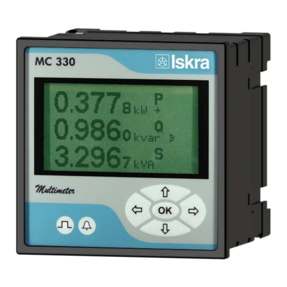
GRAPHICAL LCD A graphical LCD with back light is used for high resolution of displayed measuring quantities and for a display of selected functions when setting the device. NAVIGATION KEYBOARD The "OK" key is used for confirming the settings, selecting and exiting the display. Direction keys are used for shifting between screens and menus. LED INDICATORS LED indicators warn of a certain state of the instrument. A left (red) one is blinking as pulse output. A right (red) one is blinking when the condition for the alarm is fulfilled. Purpose and use of different types of measuring centers Energy meter MC320 The instrument is used for monitoring and measuring electric quantities of electrical power system. As the energy counter, instrument records energy in all four quadrants in four tariffs. Two different modules that are optionally built in two module places in the meter are available for controlling measurements. Available is one input and one output module. Multifunction meter MC330 The instrument is used for monitoring and measuring electric quantities of three‐phase electrical power distribution system. The meter is provided with 16 program adjustable alarms, Configuration can have one input, one output modules and communication module (RS232 or RS485 or USB). With the communication meter can be set and measurements can be checked. The meter also functions as an energy counter with tariffs. As an energy counter it can record energy in all four quadrants in four tariffs. Different modules that are optionally built in two module places in the meter are available for controlling measurements. Available is one input and one output module. 10 Measuring centres – MC320, MC330, MC350 & MC350H ‐ User’s Manual ... -
Page 19: Network Recorder Mc350 & Mc350H
BASIC DESCRIPTION AND OPERATION Network Recorder MC350 & MC350H The instrument is used for monitoring and measuring electric quantities of electrical power system. It includes all functionality of MC330 and as addition it has 8Mb of flash memory built in. So it's additional functionality is that it measures and stores selected measured quantities and alarms in to recorder, where they are available for further analysis. At tariff clock setting, four seasons and four day groups are available. Additionally, 20 places are available for setting holidays. As an energy counter it can record energy in all four quadrants in four tariffs. The meter could be provided with M‐Bus communication module. Type differences Different types differ on functionality and equipment as shown in the following table. Differences in hardware Feature MC320 MC330 MC350 MC350H ● ● ● ● Graphical LCD display ● ● ● ● Back light of LCD display ●/× ●/● ●/● ●/● LED indicator (pulse/alarm) ● ● ● ● Control keys on front panel (5) ○ ○ ● ... -
Page 20: Supported Measurements
BASIC DESCRIPTION AND OPERATION Supported measurements Basic measurements MC320 MC330 MC350 MC350H ● ● Voltage U1, U2, U3 and U~ × ● ● ● Current I1, I2, I3, In, It and I~ × ● ● ● Active power P1, P2, P3, and Pt × ● ● ● Reactive power Q1, Q2, Q3, and Qt × ● ● ● Apparent power S1, S2, S3, and St × ● ● ● Power factor PF1, PF2, PF3 and PF × ●... -
Page 21: Connection
Check protective fuse rating (the recommended maximum rating of the external protective fuse for this equipment is 6A ‐ Red Spot type or equivalent). WARNING! Wrong or incomplete connection of voltage or other terminals can cause non‐operation or damage to the device. PLEASE NOTE After connection, settings have to be performed via a keyboard on the front side of the instrument that reflect connection of device to voltage network (connection mode, current and voltage transformers ratio, …). Measuring centres – MC320, MC330, MC350 & MC350H ‐ User’s Manual ... -
Page 22: Mounting
CONNECTION Mounting 1 Before inserting device into the panel cut out, remove four screws, insert device and position the screws correctly. Fix device to the panel. Panel cut out: + 0.8 DIN 92 x 92 mm Remove protection foil from the screen. 14 Measuring centres – MC320, MC330, MC350 & MC350H ‐ User’s Manual ... -
Page 23: Electric Connection
Voltage inputs of measuring centre can be connected directly to low‐voltage network or via a voltage measuring transformer to high‐voltage network. There are two current connection options (defined when ordering): ‐ Through hole transformer ‐ Screw terminal connector Depending on your current connections, refer to connection table below. 2 Choose corresponding connection from the figures below and connect corresponding voltages and currents. Information on electrical consumption of current and voltage inputs is given in chapter Inputs on page 48. Connection 1b (1W1b); Single phase connection Connection 3b (1W3b) Three phase, three wire connection with balanced load Connection 3u (2W3u) Three phase, three wire connection with unbalanced load Connection 4b (1W4b) Three phase, four wire connection with balanced load Measuring centres – MC320, MC330, MC350 & MC350H ‐ User’s Manual ... -
Page 24: Connection Of Input/Output Modules
Tariff input module with two tariff inputs for changeover between up to four tariffs. Tariff input module with two tariff inputs for changeover between up to four tariffs. S0 (pulse) output module with two pulse outputs for energy counters. Relay output module with two outputs. (MC330, MC350, MC350H only) 16 Measuring centres – MC320, MC330, MC350 & MC350H ‐ User’s Manual ... -
Page 25: Communication Connection
Connector terminals are marked on the label on the upper side of the instrument. More detailed information on communication is given in chapter Communication on page 50. RS232 RS232 communication is intended for direct connection of the Measuring centre to the personal computer. For proper operation it is necessary to assure the corresponding connection of individual terminals (see table on next page). RS485 RS485 communication is intended for connection of devices to network where several devices with RS485 communication are connected to a common communication interface. We suggest using one of the ISKRA, d.d. communication interfaces! M‐Bus (MC350 and MC350H only) M‐Bus slave interface is intended for connection to network where M‐Bus master device is present. For more information regarding M‐Bus please refer to Appendix D on page 68. Profibus (MC330, MC350 and MC350H only) Profibus DP‐V0 communication protocol is supported. Up to 32 slave devices can be configured into the single Profibus network. Each device can be configured as a slave device providing wide range of measuring data to the Profibus master. For more information regarding Profibus please refer to Appendix C on page 63. Measuring centres – MC320, MC330, MC350 & MC350H ‐ User’s Manual ... -
Page 26: Usb
Service USB communication serves as a fast peer‐to‐terminal data link. The device is detected by host as a USB 2.0 compatible device. Service USB connection is provided through a USB mini‐B type connector. Service USB is intended only for parameterisation of the meter and is not galvanic separated. Advantage is that in this case meter does not need a power supply to communicate. Communication via service port is time limited. When using service communication, power supply and measuring voltages need to be disconnected. WARNING! Service USB communication is not galvanic separated! When using service USB communication, power supply and measuring voltages need to be disconnected! PLEASE NOTE When MC3x0x is connected to a PC through USB communication for the first time, a user is prompted to install a driver. The driver is integrated in MiQen software or can be downloaded from the Iskra, d.d. web page www.iskra.eu. With this driver installed, USB is redirected to a serial port, which should be selected when using MiQen software. 18 Measuring centres – MC320, MC330, MC350 & MC350H ‐ User’s Manual ... -
Page 27: Profibus (Mc330, Mc350 And Mc350H Only)
4 – RTS Request to send Standard USB 2.0 compatible cable recommended (mini‐ Service USB Mini‐B type B type plug) Connection of power supply Measuring centre has adaptable power supply. It enables connection to certain AC power supply or universal (AC/DC) power supply. Power supply voltage depends on ordered voltage. Information on electric consumption is given in chapter Technical data on page 47. 5 Regarding power supply voltage specification on the label choose and connect the power supply voltage: Connection of universal power supply to terminals 13 and 14. Example for MC350! Connection of AC power supply to terminals 13 and 14. Example for MC350! Measuring centres – MC320, MC330, MC350 & MC350H ‐ User’s Manual ... -
Page 28: First Steps
After correct switch‐on and respected safety measures the work with device does not represent any danger for a user. Basic concepts Navigation keys and LCD enable application and basic device settings. During the operation some icons can be displayed in upper part of LCD. The significance of icons (from right to left) is explained in the table below. Icon Meaning Device is locked with a password of the second level (L2). The first level (L1) can be unlocked. Device can be wrongly connected at 4u connection. Energy flow direction is different by phases. The device supply is too low. Clock not set (MC350, MC350H only) Example (MC330): Main menu Info OK Meaning of icons is displayed on LCD in the Information menu. 20 Measuring centres – MC320, MC330, MC350 & MC350H ‐ User’s Manual ... -
Page 29: Installation Wizard
To use instrument on the Profibus/M‐Bus network please note that installation wizard doesn’t cover Profibus/M‐ Bus settings. Profibus settings must be done as described in the Appendix C. M‐Bus settings must be done as described in the Appendix D. PLEASE NOTE All settings that are performed through the Installation wizard can be subsequently changed by means of the Settings menu or via MiQen by means of communication. Main menu Installation The menus follow one after another: START MENU Start screen is displayed on LCD. LANGUAGE Set device language. DATE (MC350, MC350H ONLY) Set device date. TIME (MC350, MC350H ONLY) Set device time. CONNECTION MODE Choose connection and define load connection. PRIMARY VOLTAGE Set primary voltage if a voltage transformer is used. SECONDARY VOLTAGE Set secondary voltage if a voltage transformer is used; set voltage of low voltage network if connection is direct. PRIMARY CURRENT Set primary current if a current transformer is used. SECONDARY CURRENT Set secondary current. COMMON ENERGY EXPONENT (MC350, MC350H ONLY) Define common energy exponent as recommended in table below, where counter divider is at default value 10. Values of primary voltage and current determine proper Common energy exponent. For detailed information see chapter Energy on page 31. Measuring centres – MC320, MC330, MC350 & MC350H ‐ User’s Manual ... -
Page 30: Display Of Device Info
Data on a device are collected in the Information menu. They include a serial number, a software version, a hardware version, date of manufacture and a number of operational hours in days, hours and minutes. Main menu Info OK Main menu Info OK Meaning of icons All possible icons with their meaning are displayed. Main menu Info OK Example of display of icons with their meaning without active icons and at locked MC: After automatic password activation 22 Measuring centres – MC320, MC330, MC350 & MC350H ‐ User’s Manual ... -
Page 31: Settings
Ethernet network. Also setting of communication parameters to establish communication with a single device can easily be done. Device settings Multi Register Edit technology assures a simple modification of settings that are organized in a tree structure. Besides transferring settings into the device, storing and reading from the setting files and memory cards are also available. Real‐time measurements All supported measurements can be seen in real time in a table or graphical form. For further processing of the results of measurements, it is possible to set a recorder on active device that will record and save selected measurements to MS Excel .csv file format. Data analysis Analysis can be performed for the devices with a built‐in memory. Recorded quantities can be monitored in a tabular or a graphical form. The events that triggered alarms can be analysed or a report on supply voltage quality can be made. All data can be exported to MS Excel worksheets. Measuring centres – MC320, MC330, MC350 & MC350H ‐ User’s Manual ... -
Page 32: Software Upgrading
MiQen setting window. Available settings of that segment are displayed in the right part by clicking any of the stated parameters. PLEASE NOTE Some settings are probably not available due to unsupported measurements and/or functions that depend on the device type. For a survey of supported measurements and functions see chapter Type differences, pages 11. 24 Measuring centres – MC320, MC330, MC350 & MC350H ‐ User’s Manual ... -
Page 33: General Settings
Date format (MC350 and MC350H only) Set a date format. Main menu Settings Date & Time Date format Date and time (MC350 and MC350H only) Set date and time of the device. Setting is important for correct memory operation, maximal values (MD), etc. Main menu Settings Date & Time Date / Time Auto Summer/Winter time (MC350 and MC350H only) If Yes is chosen, time will be automatically shifted to a winter or a summer time, regarding the time that is momentarily set. Main menu Settings Date & Time Automatic S/W time Measuring centres – MC320, MC330, MC350 & MC350H ‐ User’s Manual ... -
Page 34: Starting Current For Pf And Pa (Ma) (Mc350, Mc350H And Mc330 Only)
10 11 12 13 14 15 16 17 18 19 20 Time [min.] Present MD MD peak Input Starting current for PF and PA (mA) (MC350, MC350H and MC330 only) At all measuring inputs noise is usually present. It is constant and its influence on the accuracy is increased by decreasing measuring signals. It is present also when measuring signals are not connected and it occurs at all further calculations as very sporadic measurements. By setting a common starting current, a limit of input signal is defined where measurements and all other calculations are still performed. Starting current for all powers (mA) Noise is limited with a starting current also at measurements and calculations of powers. Starting voltage for all powers Noise is limited with a starting voltage also at measurements and calculations of powers. Until voltage reaches user defined starting voltage limit, all powers are set to 0. Using three wire electrical connections, virtual phase voltage is used in calculations. Starting voltage for SYNC (MC350, MC350H and MC330 only) If all voltages are less than Starting voltage for SYNC, than the current inputs are used for synchronisation. If all currents are less than Starting current for PF and PA, than the synchronisation is stopped and the frequency result is 0 Hz 26 Measuring centres – MC320, MC330, MC350 & MC350H ‐ User’s Manual ... -
Page 35: Reactive Power And Energy Calculation
Setting of current and voltage ratios Before setting current and voltage ratios it is necessary to be familiar with the conditions in which device will be used. All other measurements and calculations depend on these settings. Up to five decimal places can be set (up / down). To set decimal point and prefix (up / down) position the cursor (left /right) to last (empty) place or the decimal point. Settings range VT primary VT secondary CT primary CT secondary Maximal value 1638.3 kV 13383 V 1638.3 kA 13383 A Minimal value 0.1 V 1 mV 0.1 A 1 mA Main menu Settings Connection VT primary / VT secondary / CT primary / CT secondary Used voltage and current range (MC350, MC350H and MC330 only) Setting of the range is connected with all settings of alarms, where 100% represents 500 V and 5A. In case of subsequent change of the range, alarms settings shall be correspondingly changed, as well. Nominal frequency (MC350, MC350H and MC330 only) A valid frequency measurement is within the range of nominal frequency ±32 Hz. This setting is used for alarms only. Measuring centres – MC320, MC330, MC350 & MC350H ‐ User’s Manual ... -
Page 36: Wrong Connection Warning
USB Communication Has no setting. Device is automatically recognized in Windows environment if device driver has been correctly installed. For more detailed information how to handle device with USB communication use Help section in MiQen software. Service USB Communication (MC330 and MC320 only) Has no setting. Device is automatically recognized in Windows environment if device driver has been correctly installed. For more detailed information how to handle device with USB communication use Help section in MiQen software ... -
Page 37: Display
Example: Desired result: Customized screen 1 Customized screen 2 Customized screen 3 Total current Power angle (U ‐I ) Phase voltage 1 Phase current 1 Neutral current Frequency Phase power 1 Average current THD of current I Setting: Main menu Settings LCD Custom screen 1 / 2 / 3 Customized screen 1 Customized screen 2 Customized screen 3 Main menu Measurements Present values Custom OK Measuring centres – MC320, MC330, MC350 & MC350H ‐ User’s Manual ... -
Page 38: Security
A serial number of device is stated on the label, LCD (see example below) and is also accessible with MiQen software. The access to the device serial number via a keyboard Example: Main menu Info OK OK Password setting A password consists of four letters taken from the British alphabet from A to Z. When setting a password, only the letter being set is visible while the others are covered with *. A password of the first (L1) and the second (L2) level is entered, and time of automatic activation is set. Main menu Settings Security Password level 1 / Password level 2 / Password lock time Password modification A password is optionally modified; however, only that password can be modified to which the access is unlocked at the moment. Main menu Settings Security Password level 1 / Password level 2 Password disabling A password is disabled by setting the "AAAA" password. Main menu Settings Security Password level 1 / Password level 2 "AAAA" OK PLEASE NOTE A factory set password is "AAAA" at both access levels (L1 and L2). This password does not limit access. 30 Measuring centres – MC320, MC330, MC350 & MC350H ‐ User’s Manual ... -
Page 39: Password And Language
Current 1 A 5 A 50 A 100 A 1000 A Voltage 110 V ‐1 (100 mWh) 0 (1 Wh) 1 (10 Wh) 1 (10 Wh) 2 (100 Wh) 230 V 0 (1 Wh) 0 (1 Wh) 1 (10 Wh) 2 (100 Wh) 3 (1 kWh) 1000 V 0 (1 Wh) 1 (10 Wh) 2 (100 Wh) 3 (1 kWh) 4 (10 kWh) 30 kV 2 (100 Wh) 2 (100 Wh) 3 (1 kWh) 4 (10 kWh) 4* (10 kWh) * ‐ Counter divider (MiQen 2.x and above ‐ Individual Counter Resolution) should be at least 100 Measuring centres – MC320, MC330, MC350 & MC350H ‐ User’s Manual ... -
Page 40: Counter Divider (Individual Counter Resolution - Miqen 2.X And Above)
Day program sets up to 4 time spots (rules) for each day group in a season for tariff switching. A date of real time clock defines an active period. An individual period is active from the period starting date to the first next date of the beginning of other periods. The order of seasons and starting dates is not important, except when two dates are equal. In that case the season with a higher successive number has priority, while the season with a lower number will never be active. If no starting date of a season is active, the active period is 1. If the present date is before the first starting date of any period, the period is active with the last starting date. Example of settings: Season Season start day Season 1: 15.02 Season 2: 30.10 Season 3: ‐ Season 4: 01.06 Date Active season 01.01. ‐ 14.02. 2 (last in the year) 15.02. ‐ 31.05. 1 01.06. ‐ 29.10. 4 30.10. ‐ 31.12. 2 32 Measuring centres – MC320, MC330, MC350 & MC350H ‐ User’s Manual ... -
Page 41: Counter Measured Quantity
For each of four (4) counters different measured quantity can be selected. User can select from a range of predefined options referring to measured total energy or energy on single phase. Or can even select its own option by selecting appropriate quantity, quadrant, absolute or inverse function. To energy counter also pulse / digital input can be attached. In this case Energy counter counts pulses from an outside source (water, gas, energy... meter). Inputs and outputs MC3x0x can be equipped with different I/O. For its technical specifications see chapter Technical data on page 47. I/O are available also over Profibus communication – for details please look into Appendix C. For I/O 1 and 2 following options are available. Module 1 ‐ Outputs: There are two different output modules. ‐ Pulse output (solid state) ‐ Relay output (relay) Module 2 ‐ Inputs: There are two different input modules. ₋ Digital input ₋ Tariff input Tariff and digital input can be ordered as a different hardware types with different voltage levels. All modules have double input or output and are in MiQen software presented as two separate modules. Measuring centres – MC320, MC330, MC350 & MC350H ‐ User’s Manual ... -
Page 42: Pulse (S0) Module
Principle described below for pulse setting, where e is prefix, satisfies EN 62053‐31: 2001 standards pulse specifications: Examples: Expected power Pulse output settings 150 ‐ 1500 kW 1 p/1kWh 1.5 ‐ 15 MW 100 p/1MWh 15 ‐ 150 MW 10 p/1MWh 150 ‐ 1500 MW 1 p/1MWh CALCULATION OF RECOMMENDED PULSE PARAMETERS If Digital output is defined as an Alarm output, its activity (trigger) is connected to Alarm groups. Multiple alarm groups can be attached to it and different signal shapes defined. For more information on how to define alarm groups, see chapter Alarms on page 36. 34 Measuring centres – MC320, MC330, MC350 & MC350H ‐ User’s Manual ... -
Page 43: Digital Input Module
2 tariff inputs only. With the combination of 2 tariff inputs maximal 4 tariffs can be selected. ACTIVE TARIFF SELECTION TABLE: Signal presence on tariff input Active tariff Input T1/T2 Input T3/T4 Tariff 1 0 0 Tariff 2 1 0 Tariff 3 0 1 Tariff 4 1 1 Measuring centres – MC320, MC330, MC350 & MC350H ‐ User’s Manual ... -
Page 44: Alarms (Mc350, Mc350H And Mc330 Only )
Quantity, value (a current value or a MD – thermal function) and a condition for alarm switch‐on are defined for every individual alarm. MC350 supports also storing of alarms in internal memory. WARNING! New values of alarms are calculated in percentage at modification of connection settings. Alarms setting Device evident all triggered alarms and stores it in internal RAM. Statistic is valid since last power supply On and could be reset with MiQen software (See chapter Reset operations on page 38) Types of alarms VISUAL ALARM When alarm is switched on, a red LED on the meter front side is blinking (see figure shown on next page). ALARM OUTPUT (PULSE) According to the alarm signal shape the output relay will behave as shown on next page. 36 Measuring centres – MC320, MC330, MC350 & MC350H ‐ User’s Manual ... -
Page 45: Memory (Mc350 And Mc350H Only )
Recorders A and B setting Separately, for each of the recorders, settings can be set: Storage interval: sets a time interval for readings to be written to a recorder Recorded quantities: for each of 16 measurements, which are to be recorded it is possible to set a required value and its representation within storage interval (minimum, maximum …). Parameter: here monitoring quantity can be selected from a list of supported measurements. Value: representation of a value within set monitoring interval can be set to different conditions. Average value represents calculated average value Actual value represents value of recorded quantity at sampling intervals Minimum and Maximum value represents minimum or maximum of recorded quantity in selected storage interval. Minimum or maximum in this case represents averaged value according to average interval selected in General settings (see page 25). Measuring centres – MC320, MC330, MC350 & MC350H ‐ User’s Manual ... -
Page 46: Reset Operations
THERMAL MODE Current and stored MDs are reset. Main menu Resets MD values Reset the last MD period (MC350 and MC330 only) THERMAL MODE Current MD value is reset. Main menu Resets Last period MD Alarm relay (1 or 2) Off (MC350 and MC330 only) When using MiQen, each alarm output can be reset separately. On device (manually) only all alarm outputs together can be reset. All alarms are reset. Main menu Reset Reset alarm output Reset alarm statistic Clears the alarm statistic that is evidenced since last power supply On. 38 Measuring centres – MC320, MC330, MC350 & MC350H ‐ User’s Manual ... -
Page 47: Measurements
● ● ● Reactive power Q Q1 × × ○ ● Reactive power Q Q2 × × × ○ ● Reactive power Q Q3 × × × ● ● ● ○ ● Total reactive power Q Q ‐ serial ‐ option ‐ not supported Measuring centres – MC320, MC330, MC350 & MC350H ‐ User’s Manual ... - Page 48 ● MD reactive power Q−L Q var ● ● ● ● ● MD reactive power Q−C Q var ● ● ● ● ● MD apparent power S S VA ‐ serial ‐ option ‐ not supported PLEASE NOTE Basic and MD measurements have designations for recognition via LCD. In this way they can be selected via LCD for a display on customized screens. 40 Measuring centres – MC320, MC330, MC350 & MC350H ‐ User’s Manual ...
-
Page 49: Explanation Of Basic Concepts
A device measures all primary quantities with sample frequency which cannot exceed a certain number of samples in a time period. Based on these limitations (65 Hz∙128 samples) a sample factor is calculated. A sample factor (M ), depending on frequency of a measured signal, defines a number of periods for a measurement calculation and thus a number of harmonics considered in calculations. Average interval − MP Due to readability of measurements from LCD and via communication, an Average interval (M ) is calculated with regard to the measured signal frequency. The Average interval (see chapter Average interval on page 41) defines refresh rate of displayed measurements based on a sampling factor. Power and energy flow Figures below show a flow of active power, reactive power and energy for 4u connection. PLEASE NOTE Display of energy flow direction can be adjusted to connection and operation requirements by changing the Energy flow direction settings in general / connection (see page 28). Measuring centres – MC320, MC330, MC350 & MC350H ‐ User’s Manual ... -
Page 50: Present Values
MC320 does not have all described measurements supported (see chapter Type differences on pages 11) PLEASE NOTE Calculation and display of measurements depend on the device type and connection used. For more detailed information see chapters Survey of supported measurements regarding connection mode on page 39. For entry and quitting measurement display menu, the OK key is used. Direction keys (left / right / up / down) are used for passing between displays as show in example below. Example for MC330 at 4u connection mode: Main menu Main menu Measurements Present values Voltage OK 42 Measuring centres – MC320, MC330, MC350 & MC350H ‐ User’s Manual ... -
Page 51: Voltage
For correct display of PF via analogue output and application of the alarm, ePF (extended power factor) is applied. It illustrates power factor with one value as described in the table below. For a display on LCD both of them have equal display function: between ‐1 and ‐1 with the icon for inductive or capacitive load. Load C Angle [°] ‐180 ‐90 +180 (179.99) PF ‐1 0 ‐1 ePF ‐1 0 Main menu Measurements Present values PF & Power angle OK Example of analogue output for PF and ePF (MC350 and MC350H only): Measuring centres – MC320, MC330, MC350 & MC350H ‐ User’s Manual ... -
Page 52: Frequency
3 Phase voltage U V Active power P W I A Q Total reactive power Q var Average current I 1 Current I A Reactive power Q var 2 Current I A Reactive power Q var 3 Current I A Reactive power Q var 44 Measuring centres – MC320, MC330, MC350 & MC350H ‐ User’s Manual ... - Page 53 Q MD reactive power Q‐C var MD reactive power Q−C var S MD apparent power S VA MD apparent power S VA I1 MD current I1 A MD current I1 A I2 MD current I2 A MD current I2 A I3 MD current I3 A MD current I3 A Example for MC350 at connection 4u: Main menu Measurements Present values Overview OK / Measuring centres – MC320, MC330, MC350 & MC350H ‐ User’s Manual ...
-
Page 54: Alarms
MEASUREMENTS Alarms An alarm menu enables surveying state of alarms. In the basic alarm menu, groups of alarms with the states of individual alarms and data on alarm outputs are displayed in the bottom line. For each active alarm a number of an alarm is written in a certain group at a certain place: Group 1: 1 8. Dot stands for alarm not active. OK OK Survey of alarms In a detailed survey alarms are collected in groups. A number of a group and alarm is stated in the first column, a measurement designation in the second, and a condition for alarm in the third one. Active alarm is marked. Main menu Measurements Alarms OK / Demonstration measurements Demo cycling Regarding the period that is defined in settings, measurement screen cycling is started until any key is pressed. Main menu Measurements Demo cycling OK 46 Measuring centres – MC320, MC330, MC350 & MC350H ‐ User’s Manual ... -
Page 55: Technical Data
Active power 0.5 120 600 250 1250 Reactive power 0.5 500 2500 [W/var/VA] [W/var/VA] Apparent power 0.5 = 1 A = 5 A Active energy EN 62053‐21 Class 1 Active energy (optional) EN 62053‐22 Class 0.5S Reactive energy EN 62053‐23 Class 2 PLEASE NOTE * − All measurements are calculated with high harmonic signals. For voltage up to 65 Hz or less, harmonics up to 32 are measured. ** − From range *** − Par al compliance Measuring centres – MC320, MC330, MC350 & MC350H ‐ User’s Manual ... -
Page 56: Inputs
AC frequency range 40…65 Hz DC voltage range 20…300 V Consumption < 5 VA AC Voltage range 57.7, 63.5, 100, 110, 230, 240, 400, 500 V Frequency range 40…65 Hz Consumption < 3 VA Connection Permitted conductor cross‐sections Terminals Max. conductor cross‐sections 2.5 mm Voltage inputs (4) Ø 6 mm one conductor with insulation Current inputs (3) 2.5 mm Supply (2) 2.5 mm Modules (2 x 3) one conductor 48 Measuring centres – MC320, MC330, MC350 & MC350H ‐ User’s Manual ... -
Page 57: Modules
Max. current < 0.6 mA Frequency range 45 … 65 Hz ON voltage 40 ... 120 % of rated voltage OFF voltage 0 ... 10 % of rated voltage Analogue output Output range 0 … 20 mA Accuracy 0.5 % of range (MC350, MC350H, with aux. Maximum load 150 Ω power supply type H only) Max. voltage on output 5 V (open circuit current output) Linearization Linear, Quadratic Max. No. of break points Output value limits 120 % of nominal output Response time of analogue output Depends on set Average interval (8 – 256 periods) Residual ripple < 1 % p.p. Measuring centres – MC320, MC330, MC350 & MC350H ‐ User’s Manual ... -
Page 58: Communication
128 x 64 dots LCD refreshing Every 200 ms Response time Input − screen All calculations are averaged over an interval of between 8 to Input − communica on 256 periods. Present interval is 64 periods, which is 1.28 second Input − alarm at 50 Hz. Memory (MC350 & MC350H only) Capacity 8 Mb built in flash Divisions Recorders A and B Alarms recorder Selection of limit values Average, minimum, maximum actual Sampling period 1 to 60 min LED’s Pulse output Energy flow Alarm (MC350, MC350H and MC330 only) Fulfilled condition for alarm RTC backup supply Supercap Lifespan 2 days 50 Measuring centres – MC320, MC330, MC350 & MC350H ‐ User’s Manual ... -
Page 59: Safety Features
Safety features In compliance with EN 61010−1 Safety 600 V rms, installation category II 300 V rms, installation category III Pollution degree 2 Test voltage 3.7 kV rms, Directive on electromagnetic compatibility 2014/30/EU EMC In compliance with EN 61326‐1 In compliance with EN 60529 Protection Front side: IP52 Rear side (with protection cover): IP20 Ambient conditions Temperature range of operation −10 to +60°C Storage temperature range −40 to +70°C Max. storage and transport humidity 75% r.h. Enclosure Material PC, incombustibility – self‐extinguishability, in compliance with UL 94 V0 Weight Max. 500 g Measuring centres – MC320, MC330, MC350 & MC350H ‐ User’s Manual ... -
Page 60: Dimensions
TECHNICAL DATA Dimensions CASING Construction Appearance All dimensions are in mm PANEL CUT OUT 52 Measuring centres – MC320, MC330, MC350 & MC350H ‐ User’s Manual ... -
Page 61: Appendix A: Modbus Protocol
30033 Total Reactive Power Q T5 30148 30149 30026 30027 Apparent Power S T5 30158 30159 30052 30053 Apparent Power S T5 30160 30161 30054 30055 Apparent Power S T5 30162 30163 30056 30057 Total Apparent Power S T7 30156 30157 30050 30051 Measuring centres – MC320, MC330, MC350 & MC350H ‐ User’s Manual ... - Page 62 30506 30507 Energy Energy Counter 1 Exponent T2 30401 30006 Energy Counter 2 Exponent T2 30402 30007 Energy Counter 3 Exponent T2 30403 30008 Energy Counter 4 Exponent T2 30404 30009 54 Measuring centres – MC320, MC330, MC350 & MC350H ‐ User’s Manual ...
-
Page 63: Register Table For The Normalized Actual Measurements
Power Factor PF 30829 T17 1 2 Power Factor PF 30830 T17 1 3 Total Power Factor PF 30831 T17 1 CAP/IND P.F. Phase 1 (PF ) 30832 T17 1 CAP/IND P.F. Phase 2 (PF ) 30833 T17 1 CAP/IND P.F. Phase 3 (PF ) 30834 T17 1 CAP/IND P.F. Total (PF ) 30835 T17 1 Measuring centres – MC320, MC330, MC350 & MC350H ‐ User’s Manual ... - Page 64 MD Current I 30869 T16 In 3 Energy Energy Counter 1 30870 T17 Actual Energy Counter 2 30871 T17 counter value MOD 20000 is Energy Counter 3 30872 T17 returned Energy Counter 4 30873 T17 Active Tariff 30879 T1 Internal Temperature 30880 T17 100° 56 Measuring centres – MC320, MC330, MC350 & MC350H ‐ User’s Manual ...
-
Page 65: 100% Values Calculations For Normalized Measurements
A/10 2 40146 VT Secondary T4 2 40147 VT Primary T4 V/10 2 40148 Current input range (%) T16 10000 for 100% 5,00 200,00 2 40149 Voltage input range (%) T16 10000 for 100% 2,50 100,00 2 40150 Frequency nominal value T1 1000 2 Measuring centres – MC320, MC330, MC350 & MC350H ‐ User’s Manual ... -
Page 66: Data Types Decoding
Hours 00 ‐ 24 (BCD) Example: 15:42:03.75 = 7503 4215(16) Date (32 bit) bits # 31…24 Day of month 01 ‐ 31 (BCD) T10 bits # 23…16 Month of year 01 ‐ 12 (BCD) bits # 15…00 Year (unsigned integer) 1998..4095 Example: 10, SEP 2000 = 1009 07D0(16) Unsigned Value (16 bit), 2 decimal places T16 Example: 123.45 = 3039(16) Signed Value (16 bit), 2 decimal places T17 Example: ‐123.45 = CFC7(16) T_Str4 Text: 4 characters (2 characters for 16 bit register) T_Str6 Text: 6 characters (2 characters for 16 bit register) T_Str8 Text: 8 characters (2 characters for 16 bit register) T_Str16 Text: 16 characters (2 characters for 16 bit register) T_Str40 Text: 40 characters (2 characters for 16 bit register) 58 Measuring centres – MC320, MC330, MC350 & MC350H ‐ User’s Manual ... -
Page 67: Appendix B: Dnp3 Communication Protocol
0 var Object Request Response Function Qualifier Object Variation Qualifier Function Description Codes Codes Number Number Codes (hex) Codes (dec) (dec) (hex) 10 0 Binary output status with flag 1 6 10 2 Binary output status with flag 1 00, 01 ,06 129 00, 01 Measuring centres – MC320, MC330, MC350 & MC350H ‐ User’s Manual ... -
Page 68: Register Table For The Actual Measurements
30 Power Factor Total (PFt) Data ‐1 +1 CAP/IND P. F. Phase 1 (PF1) Data ‐1 CAP +1 300% for ‐1 IND 31 CAP/IND P. F. Phase 2 (PF2) Data ‐1 CAP +1 300% for ‐1 IND 32 CAP/IND P. F. Phase 3 (PF3) Data ‐1 CAP +1 300% for ‐1 IND 33 CAP/IND P. F. Total (PFt) Data ‐1 CAP +1 300% for ‐1 IND 34 35 j1 (angle between U1 and I1) Data ‐100° +100° 60 Measuring centres – MC320, MC330, MC350 & MC350H ‐ User’s Manual ... - Page 69 Energy Counter 3 Cost Data 75 (32‐bit value) MOD Energy Counter 4 Cost Data 76 (32‐bit value) MOD Total Energy Counter Cost Data 77 Aktiv Tariff T1 Data 78 79 Internal Temperature Data ‐100° +100° Measuring centres – MC320, MC330, MC350 & MC350H ‐ User’s Manual ...
- Page 70 60 2 CLASS 1 DATA 1.22* 06 60 3 CLASS 2 DATA 1.22* 06 60 4 CLASS 3 DATA 1.22* 06 *only object 30 Tests: Invalid start octets Invalid primary function code Invalid destination address Invalid CRC Invalid FCV 62 Measuring centres – MC320, MC330, MC350 & MC350H ‐ User’s Manual ...
-
Page 71: Appendix C: Profibus Protocol
Communication. Structure of the input/output telegram When Iskra MC350H Profibus enters the Data Exchange operation mode then standard SRD (Send and Request Data with acknowledge) telegrams are exchanged between Master device and MC350H device. Iskra defines one output telegrams (master to slave) and 4 input telegrams (slave to master), to provide data information being exchanged. Output telegram is used to write data into the output module registers. And the input telegrams are used to read one of four modules with measuring data. Telegrams are defined on the data section field (data field up to 244 Bytes long) inside the SDR message structure. The purpose of telegrams definition is to provide exchange of measurements data from MC350H to the Master device and to control MC350H outputs from the Master device. MC350H output telegram is defined as: Master telegram to the Slave Meaning/contents Value Header byte 0 Telegram ID – or module number of the data 1‐5 segment to be requested Header byte 1 reserved‐not used at this time Header byte 2 control byte WRXXX XXXDU Header byte 3 reserved‐not used at this time Data bytes 4‐128 up to 124 bytes of user data user data being exchanged Measuring centres – MC320, MC330, MC350 & MC350H ‐ User’s Manual ... - Page 72 Header byte 3 status byte XXXUP XXIDX Data bytes 4‐128 up to 124 bytes of user data user data being exchanged Header byte 0 indicates the module number index being requested. With this number (1‐5) MC350H indicates to the Master which module of data is being transferred inside the SRD data section. Header bytes 1 and 2 are not used. Header byte 3 is used as a status byte with the following meaning. B7 B6 B5 B4 B3 B2 B1 B0 X X X UP X X ID X With bit 4 (UP) set to 1 MC350H indicates to the Master that internal data update is in progress. Value 0 means that internal data processing completed. With bit 1 (ID) set to 1 MC350 signalizes to the Master that telegram ID inside the header byte 1 is wrong (not in the range 1‐5). This prevents errors when addressing wrong input telegrams at the Master output telegram. 64 Measuring centres – MC320, MC330, MC350 & MC350H ‐ User’s Manual ...
-
Page 73: Telegrams Table For The Actual Measurements
32594 32595 Float % 108 U2 THD% 32596 32597 Float % 112 U3 THD% 32598 32599 Float % 116 U12 THD% 32600 32601 Float % 120 U23 THD% 32602 32603 Float % 124 U31 THD% 32604 32605 Float % Measuring centres – MC320, MC330, MC350 & MC350H ‐ User’s Manual ... - Page 74 30191 32531 T1 6 Alarm Status Flags (No. 17…32) 30192 32533 T1 8 I/O 1 Value 30193 32535 T17 10 I/O 2 Value 30194 32537 T17 12 I/O 3 Value 30195 32539 T17 14 I/O 4 Value 30196 32541 T17 66 Measuring centres – MC320, MC330, MC350 & MC350H ‐ User’s Manual ...
- Page 75 Meaning inside the address start telegram Alarm/Output 1 signal 40722 T1 Relay value Relay function 4 Always ON Always OFF Alarm/Output 2 signal 40725 Relay value Relay function T1 6 Always ON Always OFF Measuring centres – MC320, MC330, MC350 & MC350H ‐ User’s Manual ...
-
Page 76: Appendix D: M-Bus
Acknowledgement (ACK = E5). If the telegram was not correctly received the MC350 will not send an acknowledgement. Select M‐BUS MC350 Using Secondary Address (SND_UD) This Telegram enables to select M‐BUS MC350. The M‐BUS MC350 confirms the correct receipt by ACK. If the telegram has not been correctly received the M‐BUS MC350 will not send an Acknowledgement. After issue of the Single Character Acknowledgement the M‐BUS MC350 is ready to transmit the entire Read‐out Data within 3 seconds from receiving the Telegram „Transmit Read‐out Data“. At the end of 3 seconds the M‐BUS MC350 will switch back to normal mode. Transmit Read‐out Data via Primary / Secondary Address (REQ_UD2) This Short Telegram enables to select the M‐BUS MC350 and to command it to transmit the Read‐out Data parameterized. The M‐BUS MC350 confirms correct receipt by transmitting of the Read‐out Data. If the Short Telegram has not been received correctly; no Data will be transmitted by the M‐BUS MC350. The Read‐out Data are sent within 35 – 75 ms from receipt of the Short Telegram by the M‐BUS Meter. Appendix D shows M‐Bus telegrams. 68 Measuring centres – MC320, MC330, MC350 & MC350H ‐ User’s Manual ... -
Page 77: M-Bus Telegrams
FB none *10 varh n‐3 R‐: *10 varh n‐3 App: none *10 VAh n ‐ 0…7 Active Tariff number Tariff number in progress (1 to 4) DIF DIFE DIFE VIFE VIFE VIFE DATA 01 DATA: value represent as 8‐bit integer Measuring centres – MC320, MC330, MC350 & MC350H ‐ User’s Manual ... -
Page 78: Active Power Total Pt (W)
04 xx.xx.xx.xx Active Power in Phase 1,2,3 (W) (nnn‐3) Active power in 32bit x10 DIF DIFE DIFE VIFE VIFE DATA 04 xx.xx.xx.xx P1: 1010 1nnn P2: 1010 1nnn P3: 1010 1nnn n ‐ 0…7 70 Measuring centres – MC320, MC330, MC350 & MC350H ‐ User’s Manual ... -
Page 79: Current In Phase 1,2,3, Neutral (A)
VIF VIFE VIFE VIFE DATA 04 xx.xx.xx.xx U1: FD 1100 nnnn U2: FD 1100 nnnn U3: FD 1100 nnnn U12: FD 1100 nnnn U23: FD 1100 nnnn U31: FD 1100 nnnn n ‐ 0…15 Measuring centres – MC320, MC330, MC350 & MC350H ‐ User’s Manual ... -
Page 80: Appendix E: Calculations & Equations
Phase number (1, 2 or 3) 8 Current sample n 9 Phase voltage sample n 10 Phase‐to‐phase voltage sample n 11 φ Power angle between current and phase voltage f (φ1, φ2 or φ3) Equations Voltage Phase voltage N ‐ 128 samples in one period (up to 65 Hz) N ‐ 128 samples in M periods (above 65Hz) Example: 400 Hz → M = 7 Phase‐to‐phase voltage , u ‐ phase voltages (U ) N ‐ a number of samples in a period 72 Measuring centres – MC320, MC330, MC350 & MC350H ‐ User’s Manual ... -
Page 81: Current
‐ active power by phases Total reactive power ‐ reactive power by phases arctan Total power angle ‐ total active power ‐ total apparent power 3 phase power factor PF ‐ phase active power ‐ phase apparent power Power factor by phases PF ‐ phase active power ‐ phase apparent power Measuring centres – MC320, MC330, MC350 & MC350H ‐ User’s Manual ... -
Page 82: Thd
APPENDIX E: CALCULATIONS & EQUATIONS THD Current THD ‐ value of first harmonic n ‐ number of harmonic Phase voltage THD ‐ value of first harmonic n ‐ number of harmonic Phase‐to‐phase voltage THD ‐ value of first harmonic n ‐ number of harmonic 74 Measuring centres – MC320, MC330, MC350 & MC350H ‐ User’s Manual ... - Page 83 ...
Need help?
Do you have a question about the MC320 and is the answer not in the manual?
Questions and answers