Advertisement
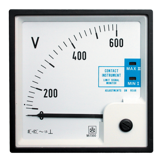
MI7350
ELECTRONIC SIGNALER
USERS MANUAL
Contents:
1. Short description of signalling apparatus
2. Operating description
3. Technical data
4. Characteristic data of signalling apparatus
1. SHORT DESCRIPTION OF SIGNALER
This is electronic signalling instrument with analog display.
Electronic is mounted in plastic housing. On the signaller front the
analog instrument displays measuring value. Signalling LED-s MAX
ΙΙ and MIN Ι indicates when measuring value is greater or lover then
limit value. On the back side of the instrument are two potentiometers
for adjusting a lower limit (CHANNEL Ι) and upper limit
(CHANNEL ΙΙ) of signaller. Also there are potentiometers for delay
time adjusting (DELAY Ι and DELAY ΙΙ).
2. OPERATING DESCRIPTION
Versions of signalling instrument provide use in various applications.
Versions of inputs provide measuring and signalling of different
physical quantities. Relay outputs can control signalling or control
elements. Limit value for lower and upper limit can be adjusted on
rear of the instrument by potentiometers in range of 0 ... 100%.
Delay of activating of relay outputs can be adjusted on rear by
potentiometers in range 0,5 ... 30 s. Pointer on scale displays value of
measuring input. LED on scale illuminates when input value becomes
greater then MAX ΙΙ limit value or lower then MIN Ι limit value.
After delay time interval if input value stays out of limit relay
energies. Relay ΙΙ deenergizes when input value is lover then MAX ΙΙ
limit value. Relay Ι deenergizes when input value is greater then MIN
Ι limit value.
3. TECHNICAL DATA
3.1. INPUTS
3.1.1
DC voltage and DC current inputs
Measuring system:
DC V - meter ranges:
Accuracy class:
Input resistance:
DC A - meter ranges:
Accuracy class:
Input resistance is range dependent on ranges.
Shunt voltage is
3.1.2
AC voltage and AC current inputs
Measuring system:
AC V - meter ranges:
AC A - meter ranges:
Instrument with moving coil for
measuring DC current.
40 mV ... 600V
1,5 %
> 10 MΩ for ranges 40 mV ... 4 V
> 1 MΩ for ranges 5 V ... 600 V
25 µA ... 5 A
1,5 %
100 mV
Instrument with moving coil and
rectifier for measuring AC current and
voltages.
100 mV ... 600 V
1 mA ... 5 A
Accuracy class:
Frequency range:
Input resistance:
3.1.3
Measuring of AC effective values
Measuring system:
AC Vef - meter ranges:
AC Aef - meter ranges:
Accuracy class:
Frequency range:
NOTE:
The signalling electronic is calibrated on r.m.s. values, at
a sine shaped wave
3.1.4
Frequency meter
Measuring ranges:
Input voltage:
3.1.5
Thermometer with thermocouple probe
Temperature probe:
Measuring ranges:
Temperature compensation:
Accuracy class:
3.1.6
Thermometer with Pt 100 resistance probe
Temperature probe:
Measuring ranges:
Connecting:
Accuracy class:
3.2 OUTPUTS
Signaller has two output relays.
Switching element:
- Output CHANNEL Ι:
- Output CHANNEL ΙΙ:
4. CHARACTERISTIC DATA OF SIGNALING APPARATUS
4.1 LIMIT VALUE AND DELAY TIME ADJUSTING
Adjusting elements are on rear side of housing:
Setting accuracy:
Setting reproducibility:
Hysteresis:
Delay time adjusting range:
Setting accuracy:
Setting reproducibility:
ATTENTION: Isolate supplies before adjusting % F.S.D. or DELAY
settings!
1,5 %
40 ... 400 Hz
> 1 MΩ; < 50 pF
Instrument with moving iron for
effective values measuring.
6 V ... 600 V
100 mA ... 5 A (5/10 A)
1,5 %
30 ... 100 Hz
45 ... 55 Hz Accuracy class: 0,5 %
48 ... 52 Hz Accuracy class: 0,5 %
45 ... 65 Hz Accuracy class: 1 %
55 ... 65 Hz Accuracy class: 0,5 %
58 ... 62 Hz Accuracy class: 0,5 %
60 ... 500 V AC
thermocouple - IEC 584-1
0 ... 250 °C ( Fe - const) J
0 ... 600 °C ( Fe - const) J
0 ... 1200 °C ( NiCr - Ni) K
0 ... 1600 °C ( PtRh - Pt) S
built-in, reference temperature 20 °C
1,5 %
Pt 100 - IEC 751
-200 ... 0 ...+ 50 °C
0 ... 250 °C
200 ... 450 °C
400 ... 650 °C
Two wires
1,5 %
potential
free
alternating
contacts. Maximal switching power at
resistive load: ≤ 600 VA (≤ 3 A,
≤ 250 V)
adjustable by MIN limit value
adjustable by MAX limit value
Range of limit value adjusting (MIN,
MAX) 0 ... 100 % F.S.D.
± 5 % (25 ... 75 %), ± 15 % (0...25 %,
75 ... 100 %)
< 2 %
< 1 % F.S.D
0,5 ... 30 s
± 20 % ± 2 s
< 2 %
relay
Advertisement
Table of Contents

Related Manuals for Iskra MI7350


Summary of Contents for Iskra MI7350
- Page 1 MI7350 Accuracy class: 1,5 % Frequency range: 40 ... 400 Hz ELECTRONIC SIGNALER Input resistance: > 1 MΩ; < 50 pF USERS MANUAL 3.1.3 Measuring of AC effective values Measuring system: Instrument with moving iron for Contents: effective values measuring.
- Page 2 5. GENERAL DATA 6.2.2 DC A - meter AC A - meter 5.1 SUPPLY AC Aeff- meter 110/230 V ± 10 % 45 ... 65 Hz or 24 V DC Power consumption: 2 VA 5.2 TEMPERATURE LIMITS Operating temperature range: 0 ... 55 °C -20 ...
Need help?
Do you have a question about the MI7350 and is the answer not in the manual?
Questions and answers