
Related Manuals for Iskra WM3M4


Summary of Contents for Iskra WM3M4
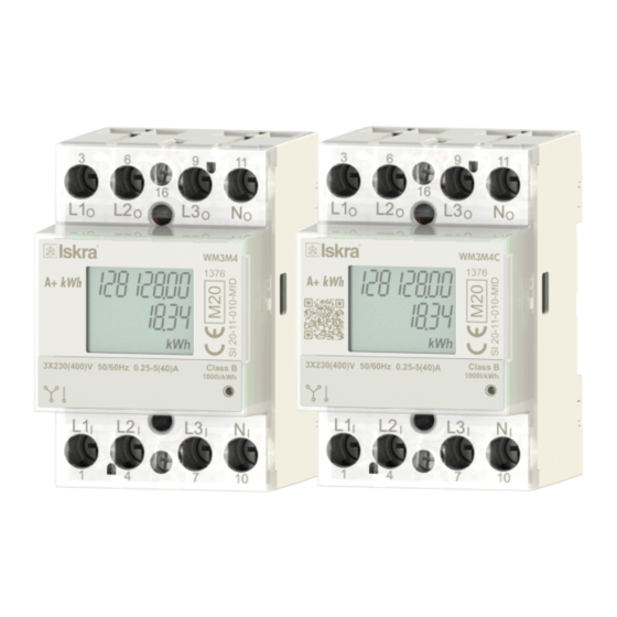
- Page 1 Three-phase electrical energy meters for charging stations WM3M4 & WM3M4C October 2020 • Version 1.07 User’s Manual...
- Page 2 HREE HASE LECTRICAL NERGY ETERS FOR HARGING TATIONS Three-phase electrical energy meters for charging stations WM3M4 & WM3M4C User and Installation manual User’s Manual WM3M4 &WM3M4C...
- Page 3 PLEASE NOTE This booklet contains instructions for installation and use of a three-phase energy meters WM3M4 & WM3M4C. Installation and use of a device also includes handling with dangerous currents and voltages therefore should be installed, operated, serviced and maintained by qualified personnel only.
- Page 4 The manufacturer or provider shall take waste electrical and electronic equipment free of charge. The complete procedure after lifetime should comply with the Directive 2002/96/EC about restriction on the use of certain hazardous substances in electrical and electronic equipment. User’s Manual WM3M4 &WM3M4C...
-
Page 5: Table Of Contents
Table of contents BASIC DESCRIPTION AND OPERATION ESCRIPTION OF THE DEVICE ARDWARE DESCRIPTION AIN FEATURES CONNECTION OUNTING LECTRICAL CONNECTION FIRST STEPS ISPLAY OF DEVICE INFO ELCOME SCREENS LCD D ISPLAY INFORMATION SETTINGS NTRODUCTION EN SOFTWARE ONNECTION ETTINGS EASUREMENTS MEASUREMENTS NLINE MEASUREMENTS ELECTION OF AVAILABLE QUANTITIES ALCULATION AND DISPLAY OF MEASUREMENTS User’s Manual... - Page 6 ONSUMPTION MEASURING AND DIGITAL SIGNING PROCEDURE RYPTO EGISTER EFINITIONS OWER LOSS BEHAVIOUR NEXPECTED RESET BEHAVIOUR TECHNICAL DATA CCURACY ECHANICAL CHARACTERISTICS OF INPUT LECTRICAL CHARACTERISTICS OF INPUT AFETY AND AMBIENT CONDITIONS EU D IRECTIVES CONFORMITY IMENSIONS ABBREVIATION/GLOSSARY User’s Manual WM3M4 &WM3M4C...
-
Page 7: Basic Description And Operation
ASIC DESCRIPTION AND OPERATION 1 BASIC DESCRIPTION AND OPERATION The following chapter presents basic information about WM3M4 & WM3M4C three-phase energy meters required to understand its purpose, applicability and basic features connected to its operation. In this chapter you will find:... - Page 8 The WM3M4 & WM3M4C energy meters are MID certified meters, intended for energy measurements in the three-phase and single-phase electrical charger stations. The WM3M4C energy meter features high temperature operation and digital signing for a charging event, whereas WM3M4 features only high temperature operation. Both meters measure energy directly in 4-wire networks according to the principle of fast sampling of voltage and current signals.
- Page 9 ASIC DESCRIPTION AND OPERATION 1.2 Hardware description The whole system of the WM3M4 & WM3M4C energy meters is equipped with the following units: Stand-alone unit. Power supply unit. Process unit (MCU microcontroller) with IR communication, LED display, LCD support, and EEPROM.
-
Page 10: Connection
ONNECTION 2 CONNECTION This chapter deals with the instructions for connection of the WM3M4 & WM3M4C energy meters. Both the use and connection of the device include handling with dangerous currents and voltages. The connection shall thus be performed ONLY by a qualified person using appropriate equipment. ISKRA, d.o.o. -
Page 11: Mounting
ONNECTION 2.1 Mounting The WM3M4 & WM3M4C energy meters are intended for DIN-rail mounting. In the case of using the stranded wire, the ferrule must be attached before the mounting. Figure 2: Dimensional drawing and rear connection terminals position User’s Manual WM3M4 &WM3M4C... - Page 12 Length or removed isolation: 10 mm Communication terminals: Contact capacity: 1 mm … 2.5 mm Connection screws: M3 Maximum torque: 1.2 Nm (PZ2) Length or removed isolation: 8 mm PLEASE NOTE Neutral wire must be connected to the meter. User’s Manual WM3M4 &WM3M4C...
- Page 13 ONNECTION Figure 3: Three - phase connection diagram Figure 4: Single-phase connection diagram User’s Manual WM3M4 &WM3M4C...
-
Page 14: First Steps
IRST TEPS 3 FIRST STEPS Programming WM3M4 & WM3M4C energy meters is very transparent and user-friendly. Numerous settings are organized in groups according to their functionality. In this chapter you will find basic programming steps: Display of device info Welcome screens LCD Display information User’s Manual WM3M4 &WM3M4C... - Page 15 Figure 6: LCD segment test FW identification window and MID relevant counters: MID unlock counter FW upgrade counter CRC of main FW CRC of measuring modules FW FW version Figure 7: FW identification window and MID relevant counters User’s Manual WM3M4 &WM3M4C...
- Page 16 BIT 1 Duration Charging power (e.g.: 3h 13min 42s) Status LCD: Table 5 digit: Clock status (see Energy BIT 0 Table 6 digit: Charging status (see consumption digit: Reserved digit: Reserved Table 1: LCD ROW2 Configuration User’s Manual WM3M4 &WM3M4C...
- Page 17 Not sync (U) Informative clock Synchronized clock Relative clock Table 5: Clock sync status Register 47000 Value Charging Status LCD status Not charging (Idle) Charging Charging after power down Charging after meter reset Table 6: Charging status User’s Manual WM3M4 &WM3M4C...
- Page 18 BIT0 and BIT2 are set, so we have Parameter CRC Error and MID-lock Error. In case the meter is in Error state the start of charging process with digital signiture is blocked and the meter needs to be replaced. 3.3.2 List of available characters on LCD 0,O,1,I,l,2,3,4,5,S,6,G,7,8,9,A,B,b,C,D,d,E,F,H,L,J,N,P,R,U,V,c,h,i,r,n,o,v,u,t,- User’s Manual WM3M4 &WM3M4C...
-
Page 19: Settings
Available settings of that segment are displayed in the right part by clicking any of the stated parameters. In this chapter, you will find a detailed description of all WM3M4 & WM3M4C energy meters features and settings. The chapter is organized in a way to follow settings organization as in setting software MiQen. -
Page 20: Introduction
(size 1 DIN module) and MiQen software version. 4.2 MiQen software MiQen software is a tool for complete programming and monitoring of ISKRA measuring instruments, connected to a PC via serial communication or by a special WM-USB adapter. A user-friendly interface consists of six segments: devices management (Connection), instrument settings (Settings), real-time measurements (Measurements), data analysis (Analysis), saved preffered devices (My Devices –... -
Page 21: Connection
MEMORY INFO : shows available memory since last official data transfer HELP : for more detailed information how to handle a device MiQen software is required for programming and monitoring the WM3M4 & WM3M4C energy meters. Software installation downloaded from https://www.iskra.eu/en/Iskra-... - Page 22 A Communication port window opens with different communication interfaces. The WM3M4 & WM3M4C energy meters supports only serial communication, so only serial communication parameters can be set. Figure 12: Communication port window Start communicating with a device Click on the REFRESH button and devices information will be displayed.
-
Page 23: Settings
This can be done with a right click on a mouse on a certain parameter. Afterwards, a window is shown with a save and a read icon. Figure 15: Save and read parameters window Those icons can also be found on a top bar. Settings values colored in gray are informative nature only. User’s Manual WM3M4 &WM3M4C... - Page 24 ETTINGS Identification window: Figure 16: WM3M4 Identification window Figure 17: WM3M4C Identification window Type Serial number Software version Hardware version Accuracy class Calibration voltage Calibration current Communication Digital signature algorithm (supported only for WM3M4C) ...
- Page 25 Figure 19: Operating mode window Date and time: date and time cannot be changed. UTC time offset: it is the difference in hours and minutes from Coordinated Universal Time (UTC) for a particular place and date. User’s Manual WM3M4 &WM3M4C...
- Page 26 The time to be waited between the attempts is included. Digital signature format: the energy meter supports ASN.1 and 64 signature format (valid only for WM3M4C). Figure 21: Digital signature format window User’s Manual WM3M4 &WM3M4C...
- Page 27 5 s to 60 s. Display MID info screen: displays FW identification screen and MID relevant counters on LCD for a chosen period of time up to 60 seconds (see chapter Welcome screens and item 6.5.16). User’s Manual WM3M4 &WM3M4C...
- Page 28 >depending on a serial number of the device). The BP password is available in the user support department in ISKRA d.o.o., and is entered instead of the password PL1 or/and PL2. Do not forget to state the device serial number when contacting the personnel in ISKRA d.o.o.
-
Page 29: Measurements
4.4.2.1 Counters The WM3M4 & WM3M4C energy meters have two unresettable counters for which MID approval is valid. The setting of these counters is fixed in the production and the setting parameters cannot be modified during use and counters cannot be reset. - Page 30 For further processing of the results of measurements, it is possible to set a recorder ( button) on the active device that will record and save selected measurements to MS Excel .csv file format. Figure 29: Measurements Recorder User’s Manual WM3M4 &WM3M4C...
-
Page 31: Measurements
EASUREMENTS 5 MEASUREMENTS The WM3M4 & WM3M4C energy meters ensure active energy measurement and actual measurements of other parameters of three phase network. The meters perform measurements with a constant sampling frequency of 3906.25 Hz. Online measurements Selection of available quantities Calculation and display of measurements User’s Manual WM3M4 &WM3M4C... - Page 32 EASUREMENTS 5.1 Online measurements Online measurements are available on display or can be monitored with setting and monitoring software MiQen. Figure 30: Online measurements window. Figure 31: Charge control window. User’s Manual WM3M4 &WM3M4C...
- Page 33 Phase-to-phase angle x-y_RMS Metering Energy Counter E Other Miscellaneous measurements Frequency Temperature Status Checksum status Further description is available in following subchapters Table 8: Selection of available measurement quantitie User’s Manual WM3M4 &WM3M4C...
- Page 34 ���� ���� ��=1 �� ���� �� Figure 32: Voltage equations All voltage measurements are available through communication. 5.3.2 Current WM3M4 & WM3M4C energy meter measures: real effective (RMS) value of phase currents �� ∑ �� ��=1 �� = √...
- Page 35 5.3.7 Harmonic distortion The WM3M4 & WM3M4C energy meters calculate THD for phase currents and phase voltages and are expressed as percent of high harmonic components regarding to fundamental harmonic. User’s Manual WM3M4 &WM3M4C...
-
Page 36: Digital Signature (Valid Only For Wm3M4C)
IGNATURE VALID ONLY FOR WM 6 DIGITAL SIGNATURE (VALID ONLY FOR WM3M4C) Introduction Digital signing procedure Energy meter cryptographic functions explanation Consumption measuring and digital signing procedure Crypto Register Definitions Power loss behaviour NEXPECTED RESET BEHAVIOUR User’s Manual WM3M4 &WM3M4C... -
Page 37: Introduction
(customer info, time, etc.) to energy meter via MODBUS communication. Energy meter adds measured energy and generates final billing message with digital signature. EV charger control unit then reads complete billing information with measured energy consumption and digital signature. User’s Manual WM3M4 &WM3M4C... -
Page 38: Energy Meter Cryptographic Functions Explanation
Crypto chip generates signature in less than a second. Algorithm is documented in: FIPS 186-4 specification http://nvlpubs.nist.gov/nistpubs/FIPS/NIST.FIPS.186-4.pdf 6.3.6 Exporting billing dataset including signature Complete billing dataset and digital signature are available for readout via MODBUS communication. User’s Manual WM3M4 &WM3M4C... -
Page 39: Crypto Register Definitions
40204 Stop Bit 1 Stop bit 2 Stop bits 40205 Parity No parity Odd parity Even parity 40206 Data Bits 8 bits Table 9: RS485 communication parameters table Default settings: Baud rate: 115200 Parity: None Stop bits: 1 User’s Manual WM3M4 &WM3M4C... - Page 40 BIT 0. 47071 Clock synchronization status (see Table 47072 Clock synchronization timeout 47073 UTC / local time format 47074 Time adjustment (-3 seconds to +3 seconds) 47075 MID Status LCD screen Table 10: Cryptographic control registers User’s Manual WM3M4 &WM3M4C...
- Page 41 47054 : high 16 bits 47055 : low 16 bits Example: Unix time: 1570096309 hex:0x5D95C4B5 Write 0x5D95 to 47054 Write 0x C4B5 to 47055 The best practice is to set time at start of every charging procedure. User’s Manual WM3M4 &WM3M4C...
- Page 42 47074. 6.5.5 Signature format Energy meter supports hex (ASN.1) and Base 64 signature format in register 48188. Format can be set in register 47059: Value Signature format HEX (ASN.1) Base64 Table 13: Signature format User’s Manual WM3M4 &WM3M4C...
- Page 43 Tariff Change Active state ‘S’ (0x53) Suspended command Active state ‘r’ (0x72) End measurement (with Active state begin and end) ‘f’ (0x66) Fiscal Reading Any state ‘h’ (0x68) Hold command Active state Table 15: Transaction commands User’s Manual WM3M4 &WM3M4C...
- Page 44 6.5.14 Public key Public key is stored in 64 bytes raw format at MODBUS address 48124. For Transparenz Software check, public key header should be prepended: 3059301306072A8648CE3D020106082A8648CE3D03010703420004 For checking with ECDSA, public key header is: 04. User’s Manual WM3M4 &WM3M4C...
- Page 45 "PG":"", "MV":"", "MM":"", "MS":"", "MF": "", "IS":true, "IF":[ "RFID_PLAIN", "OCPP_RS_TLS" "IT":"ISO14443", "ID":"1F2D3A4F5506C7", "CT":"EVSEID", "CI":"", "RD":[] Fields highlighted in green are mandatory. Energy meter fills following values: PG:”T<signature counter>” or “F<fiscal counter>” for fiscal readings MV:“Iskra” MM:”WM3M4” User’s Manual WM3M4 &WM3M4C...
- Page 46 "RV":123457.529, "RI":"1-b:1.8.0", "RU":"kWh", "RT":"AC", "EF":"", "ST":"G" "TM":"2019-11-11T13:24:12,000+0000 S", "TX":"E", "RV":123457.529, "RI":"1-b:1.8.0", "RU":"kWh", "RT":"AC", "EF":"", "ST":"G"} Highlighted data is generated by energy meter. Data is without whitespaces (newline characters are added in this document for better readability). User’s Manual WM3M4 &WM3M4C...
- Page 47 Displayed MID info is in two rows on LCD display: Number of MID unlocks (2 digits) Firmware CRC (4 digits) Number of SW upgrades (2 digits) Phase module CRC (4 digits) Figure 34: Status LCD shows FW versions User’s Manual WM3M4 &WM3M4C...
- Page 48 47033 47034 Fiscal Reading Counter value T_32U 47035 47036 Hold measurement T_Unix Timestamp 47039 47040 Hold measurement T_Unix Timestamp 47041 47042 Hold measurement Counter T_32U value 47039 47040 Suspend Timestamp T_Unix 47041 47042 Suspend Counter value T_32U Table 16: Measurements table User’s Manual WM3M4 &WM3M4C...
-
Page 49: Power Loss Behaviour
Meter will generate and sign complete transaction with time error flag (“EF”: “t”). 6.7 Unexpected reset behaviour Meter will set Energy error flag (“EF”: “E”) if unexpected reset happens during charging. Measured energy consumption is not valid. User’s Manual WM3M4 &WM3M4C... -
Page 50: Technical Data
ECHNICAL DATA 7 TECHNICAL DATA In following chapter all technical data regarding operation of WM3M4 & WM3M4C energy meters are presented. Accuracy Mechanical characteristics of input Electrical characteristics of input Safety and ambient conditions EU Directives conformity Dimensions User’s Manual WM3M4 &WM3M4C... -
Page 51: Accuracy
... 25 (16) mm Connection screws: Maximum torque: 3.5 Nm (PZ2) Length of removed isolation: 10 mm Communication terminals Contacts capacity: 1 mm ... 2.5 mm Connection screws: Maximum torque: 1.2 Nm (PZ2) Length or removed isolation: 8 mm User’s Manual WM3M4 &WM3M4C... -
Page 52: Electrical Characteristics Of Input
8, N, 1 Protocol: MODBUS RTU Address: 33 – (default) Optical communication Type: Connection: via WM-USB adapter Speed: 19200 bit/s Frame: 8, N, 1 Protocol: MODBUS RTU Address: 33 – (locked) Remark: All settings are fixed User’s Manual WM3M4 &WM3M4C... -
Page 53: Safety And Ambient Conditions
DIN rail 35 mm Dimensions (W x H x D): 53,6 mm x 84 mm x 69,4 mm Package dimensions (W x H x D): 57 mm x 93 mm x 85 mm Colour: RAL 7035 User’s Manual WM3M4 &WM3M4C... -
Page 54: Eu Directives Conformity
EN 62059-32-1:2012 Electricity metering equipment - Dependability - Part 32-1: Durability - Testing of the stability of metrological characteristics by applying elevated temperature CLC/TR 50579:2012 Electricity metering equipment - Severity levels, immunity requirements and test methods for conducted disturbances in the frequency range 2 -150 kHz User’s Manual WM3M4 &WM3M4C... -
Page 55: Dimensions
ECHNICAL DATA 7.6 Dimensions 7.6.1 Dimensional drawing Construction Appearance All dimensions are in mm Dimensions User’s Manual WM3M4 &WM3M4C... -
Page 56: Abbreviation/Glossary
Abbreviations are explained within the text where they appear the first time. Most common abbreviations and expressions are explained in the following table: Term Explanation MODBUS / DNP3 Industrial protocol for data transmission MiQen Setting Software for ISKRA instruments Alternating Infrared (optical) communication Root Mean Square Power angle (between current and voltage) Power factor Total harmonic distortion... - Page 57 Published by Iskra, d.o.o. • Subject to change without notice • Version 1.07 October 2020 • EN K22.433.922...
Need help?
Do you have a question about the WM3M4 and is the answer not in the manual?
Questions and answers