
Related Manuals for Iskra iMC7 4 Series


Summary of Contents for Iskra iMC7 4 Series
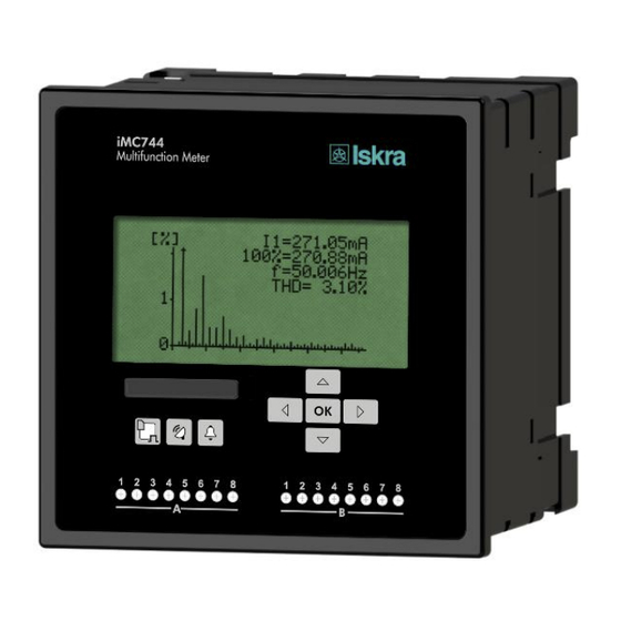
- Page 1 Power Monitoring Device iMC7x4 Multifunction Meter iMC744 Network Recorder iMC754 Quality Analyzer iMC774 July 2021 • Version 1.00 User’s Manual...
- Page 2 Power Monitoring Device iMC7x4 User and Installation manual Contents of consignment The consignment includes: Multifunction Meter iMC744/Network Recorder iMC754/Quality Analyzer iMC774 Quick installation manual User’s Manual...
- Page 3 Power Monitoring Device also includes handling with dangerous currents and voltages therefore should be installed, operated, serviced and maintained by qualified personnel only. ISKRA Company assumes no responsibility in connection with installation and use of the product. If there is...
- Page 4 Basic Description and Operation WARNING! Auxiliary power supply can be LOW range (19-70V , 48-77V ). Connecting device with LOW power supply to higher voltage will cause device malfunction. Check devices’ specification before turn it on! Used symbols on devices’ housing and labels ...
-
Page 5: Table Of Contents
Contents BASIC DESCRIPTION AND OPERATION NTRODUCTION ESCRIPTION OF THE DEVICE URPOSE AND USE OF THE DEVICE EATURES SUPPORTED OPTIONS AND FUNCTIONALITY CONNECTION NTRODUCTION OUNTING LECTRICAL CONNECTION MC774) ONNECTION OF AUX POWER SUPPLY VALID ONLY FOR I FIRST STEPS ASIC CONCEPTS NSTALLATION WIZARD ISPLAY OF DEVICE INFO SETTINGS... - Page 6 Basic Description and Operation MEASUREMENTS NTRODUCTION ELECTION OF AVAILABLE QUANTITIES XPLANATION OF BASIC CONCEPTS ALCULATION AND DISPLAY OF MEASUREMENTS RESENT VALUES AX VALUES LARMS ILLING ARMONIC ANALYSIS PQ A MC774) NALYSIS VALID ONLY FOR I EMOTE DISPLAY FEATURES COMMUNICATION MODES PULL COMMUNICATION MODE MQTT...
-
Page 7: Basic Description And Operation
Basic Description and Operation Basic Description and Operation The following chapter presents basic information about iMC7x4 Power Monitoring Device required to understand its purpose, applicability and basic features connected to its operation. Besides that, this chapter contains navigational tips, description of used symbols and other useful information for understandable navigation through this manual. -
Page 8: Introduction
Basic Description and Operation Introduction Regarding the options of a iMC7x4 Power Monitoring Device, different chapters should be considered since it might vary in functionality and design. More detailed description of device functions is given in chapter Main Features, supported options and functionality, page 9. Power Monitoring Device iMC7x4 is available in housing for panel mounting. - Page 9 MODBUS / DNP3 Industrial protocol for data transmission Memory card Multimedia memory card. SD supported. MiQen Setting Software for ISKRA instruments PA total Power Angle calculated from total active and apparent power Angle between fundamental phase voltage and phase current phase...
- Page 10 Basic Description and Operation Status (watchdog) module – for supervision of proper operation Bistable alarm output module Analogue output module Digital input module COM2 communication port module Analogue output module Analogue input module Alarm output module Digital input module Digital output module User’s Manual...
-
Page 11: Description Of The Device
Basic Description and Operation Description of the device iMC7x4 Power Monitoring Device is a comprehensive device intended for permanent monitoring of power quality from its production (especially renewable), transmission, distribution to final consumers, who are most affected by insufficient quality of voltage. It is mostly applicable in medium and low voltage markets. -
Page 12: Led Indicators
Basic Description and Operation LED indicators There are two types of LED indicators positioned on the front panel. General operation LED indicators and I/O status LED indicators. General operation LED indicators warns of a certain state of the device. A left (red) indicator indicates the card activity and that it should not be pulled out. -
Page 13: Purpose And Use Of The Device
Basic Description and Operation Purpose and use of the device Multifunction Meter iMC744 The instrument is used for monitoring and measuring electric quantities of three-phase electrical power distribution system. The meter is provided with 32 program adjustable alarms, up to four input or output modules and communication. - Page 14 Basic Description and Operation The internal memory capacity enables storing of more than 170,000 variations of the measurements from the standard values, which enables finding eventual reasons for the problems in network. Limits and required quality in a monitored period can be defined for each monitored characteristic.
-
Page 15: Main Features , Supported Options And Functionality
Basic Description and Operation Main Features, supported options and functionality iMC7x4 Power Monitoring Device is a perfect tool for monitoring and analysing medium or low voltage systems in power distribution and industrial segments. It can be used as a standalone PQ monitoring device for detection of local PQ deviations. - Page 16 Basic Description and Operation General hardware Features Default / Default / Default / Optional Optional Optional iMC744 iMC754 iMC774 General ● Class A measuring accuracy according to EN 61000-4- × × ● ● ● Voltage auto range up to 1000Vp-p ●...
- Page 17 Basic Description and Operation General hardware Features Default / Optional iMC774 Input and output modules Input / output module 1 2×AO / 2×AI / 2×RO / 2×PO / 2×PI / 2×TI / 1×BO / 2×DI / WO+RO ○/○/○/○/○/○/○/○/○ Input / output module 2 2×AO / 2×AI / 2×RO / 2×PO / 2×PI / 2×TI / 1×BO / 2×DI / WO+RO ○/○/○/○/○/○/○/○/○...
- Page 18 Basic Description and Operation General software Features Default Default Default optional optional optional iMC744 iMC754 iMC774 ● ● ● Setup wizard ● ● ● Wrong connection warning ● ● ● Custom screen settings (3 user defined screens on LCD) ● ●...
-
Page 19: Connection
Both the use and connection of the device includes handling with dangerous currents and voltages. Connection shall therefore be performed ONLY a by a qualified person using an appropriate equipment. ISKRA, d.o.o. does not take any responsibility regarding the use and connection. If any doubt occurs regarding connection and use in the system which device is intended for, please contact a person who is responsible for such installations. -
Page 20: Introduction
Pluggable terminals for connection of inputs, aux. Power supply and I/O modules Short installation manual This document and settings software MiQen can also be found on our web page: https://www.iskra.eu/en/Iskra-Software/. CAUTION Please examine the equipment carefully for potential damages which might arise during transport! -
Page 21: Before Use
CONNECTION Before use Before use please check the following: Nominal voltage (U = 1000V = 600V P-Pmax ACrms P-Nmax ACrms Supply voltage (type HIGH or type LOW), Nominal frequency, Voltage ratio and phase sequence, Current transformer ratio and terminals integrity, Protection fuse for voltage inputs (recommended maximal external fuse size is 6 A) External switch or circuit-breaker must be included in the installation... -
Page 22: Mounting
CONNECTION Mounting iMC7x4 Power Monitoring Device is intended only for panel mounting. Pluggable connection terminals allow easier installation and quick replacement should that be required. This device is not intended for usage as portable equipment and should be used only as a fixed panel mounted device. Dimensional drawing and rear connection terminals position iMC744 and iMC754 Dimensional drawing and rear connection terminals position iMC774 Recommended panel cut out is:... -
Page 23: Electrical Connection
CONNECTION Electrical connection Voltage inputs of a device can be connected directly to low-voltage network or via a voltage measuring transformer to a high-voltage network. Current inputs of a device are led through a hole in current transformers to allow uninterrupted current connection. - Page 24 CONNECTION Connection 3u (2W3) Three-phase – three- wire connection with unbalanced load Connection 4b (1W4) Three-phase – four-wire connection with balanced load Connection 4u (3W4) Three-phase – four-wire connection with unbalanced load PLEASE NOTE Examples of connections are given for device with built in two input / output modules and RS232 / RS485 communication.
-
Page 25: Connection Of Input/Output Modules
CONNECTION Connection of input/output modules WARNING Check the module features that are specified on the label, before connecting module contacts. Wrong connection can cause damage or destruction of module and/or device. PLEASE NOTE Examples of connections are given for device with built in two input / output modules and RS232 / RS485 communication. - Page 26 CONNECTION 2 (terminal numbers 15-20) I/O module 1 and – input options Tariff input module with two tariff inputs for changeover between up to four tariffs. Digital input module with two digital inputs enables reception of impulse signals. Pulse input module enables reception of pulses from various counters (water, gas, heat, flow…).
- Page 27 CONNECTION Auxiliary I/O module A and B – input options (valid only for iMC774) Digital input module with eight digital inputs enables reception of digital signals. Synchronisation module C (valid only for iMC774) Synchronisation module is equipped with support for two different synchronisation methods IRIG-B and GPS modem.
- Page 28 CONNECTION Memory Card iMC7x4 Power Monitoring Device is equipped with a front panel slot for a SD memory card that supports capacity up to 2 GB. CAUTION When memory slot is not used it should be covered with attached cover to avoid penetration of dust and small objects.
-
Page 29: Communication Connection
CONNECTION Communication connection Primary communication interface (COM1) type is normally specified when placing an order. Device can support several types of communication: serial RS232/ 485 communication designed as a pluggable 5-pole screw terminal connector, Ethernet communication designed as standard RJ-45 terminal and USB communication designed as standard USB-B type terminal Single USB communication designed as standard USB-B type terminal PLEASE NOTE... - Page 30 The driver is provided on the CD, enclosed in the original shipment package, or it can be downloaded from the ISKRA, d.o.o. web page www.iskra.eu. With this driver installed, USB is redirected to a serial port, which should be selected when using MiQen setting software.
- Page 31 CONNECTION Connection of Real Time Synchronization module C (valid only for iMC774) Synchronized real-time clock (RTC) is an essential part of any Class A analyzer for proper chronological determination of various events. To distinct cause from consequence, to follow a certain event from its origin to manifestation in other parameters it is very important that each and every event and recorded measurement on one instrument can be compared with events and measurements on other devices.
- Page 32 CONNECTION Network time protocol (NTP): Synchronization via Ethernet requires access to a NTP server. PLEASE NOTE NTP can usually maintain time to within tens of milliseconds over the public Internet, but the accuracy depends on infrastructure properties - asymmetry in outgoing and incoming communication delay affects systematic bias.
-
Page 33: ( Valid Only For Imc774)
CONNECTION Connection of aux. power supply (valid only for iMC774) Device can be equipped with either of two types of universal (AC/DC) switching power supply. Type High: 70...300 V DC 80...276 V AC; 40...65 Hz Type Low: 19...70 V DC 48...77 V AC;... -
Page 34: First Steps
FIRST STEPS FIRST STEPS Programming iMC7x4 Power Monitoring Device is very transparent and user friendly. Numerous settings are organized in groups according to their functionality. Programming iMC7x4 Power Monitoring Device can be performed using the keypad and display on the front panel. Due to representation of certain settings not all settings can be programmed this way. -
Page 35: Basic Concepts
FIRST STEPS Basic concepts Navigation keypad and LCD enable basic device settings. During the operation some icons can be displayed in upper part of LCD. The significance of icons (from right to left) is explained in the table below. Table 4: Survey of notification icons Icon Meaning Device is locked with a password of the second level (L2). - Page 36 FIRST STEPS PLEASE NOTE All settings that are performed through the Installation wizard can be subsequently changed by means of the Settings menu or via MiQen by means of communication or a Memory card. When entering installation wizard following display is shown: Installation Welcome to the Installation Wizard.
- Page 37 FIRST STEPS Common energy counter resolution Define Common energy counter resolution as recommended in table below, where Individual counter resolution is at default value 10. Values of primary voltage and current determine proper Common energy counter resolution. For detailed information about setting energy parameters see chapter Energy. Table 5: Suggested Common energy counter resolutions Current 50 A...
-
Page 38: Display Of Device Info
FIRST STEPS Display of device info A menu is divided into several submenus with data and information about device: Welcome screen When entering the information menu, a welcome screen is displayed on LCD showing type designation and name of power monitoring device. Information Serial number, Hardware and Firmware version, date of calibration and operational time. -
Page 39: Settings
SETTINGS SETTINGS A setting structure, which is similar to a file structure in an explorer is displayed in the left part of the MiQen setting window. Available settings of that segment are displayed in the right part by clicking any of the stated parameters. In this chapter you will find detailed description of all iMC7x4 features and settings. -
Page 40: Introduction
(beep). MiQen software MiQen software is a tool for a complete programming and monitoring of ISKRA measuring instruments. Remote operation is possible by means of serial (RS485/RS232), USB or TCP/IP communication in connection with a PC. A user- friendly interface consists of five segments: devices management, device settings, real-time measurements, data analysis and software upgrading. -
Page 41: Devices Management
Connect a device to a communication interface Depending on type of communication interface connect a device: Directly to a PC using RS232 cable To comm. adapter RS485 / RS232 (suggested adapter is ISKRA MI485) Directly to a PC using USB cable Network connection using Ethernet cable... - Page 42 The driver is provided on the CD, enclosed in the original shipment package, or it can be downloaded from the ISKRA d.o.o. web page www.iskra.eu. With this driver installed, USB is redirected to a serial port, which should be selected when using MiQen setting software.
-
Page 43: Device Settings
SETTINGS Start communicating with a device Click on REFRESH button and devices information will be displayed When devices are connected to a network and a certain device is required it is possible to browse a network for devices. For this purpose choose Scan the network when device is connected to a RS485 bus Browse ethernet devices when device is connected to the Ethernet Device settings... - Page 44 SETTINGS PLEASE NOTE When finished programming, changes should be confirmed by pressing Download settings button in MiQen menu bar ( ) or with a mouse right click menu. PLEASE NOTE When finished programming, all settings can be saved in a setting file (*.msf file). This way it is possible to archive settings in combination with a date.
-
Page 45: Real-Time Measurements
SETTINGS Real-time measurements Measurements can be seen ONLINE when device is connected to aux. power supply and is communicating with MiQen. When device is not connected it is possible to see OFFLINE measurements simulation. The latter is useful for presentations and visualisation of measurements without presence of actual device. -
Page 46: Data Analysis
SETTINGS Different measuring data can be accessed by means of tabs (Measurements, Min/Max …) in the lower part of MiQen window. For further processing of the results of measurements, it is possible to set a recorder button) on active device that will record and save selected measurements to MS Excel .csv file format. -
Page 47: Software Upgrading
SETTINGS Window for a choice of memory data to be analysed After data is read or imported recorded quantities can be monitored in a tabular or a graphical form. The events that triggered alarms can be analyzed or a report on supply voltage quality can be made. -
Page 48: General Settings
SETTINGS General settings Main menu Settings Measurements General Settings Date & Time Resets Connection SD card Communication Info Installation Security 14.04.2021 16:53:36 Energy Inputs/Outputs Main menu General settings are essential for iMC7x4 Power Monitoring Device. They are divided into four additional sublevels (Connection, Communication, Display and Security). - Page 49 SETTINGS Language Set language for display. When language is changed from or to Russian, characters of the password are changed too. For overview of character translation see chapter Password and language. Main menu Settings General Language Currency Choose currency for evaluating energy cost (see chapter Energy).
- Page 50 SETTINGS Real Time synchronisation source (valid only for iMC774) Synchronized real-time clock (RTC) is an essential part of any Class A analyzer for proper chronological determination of various events. To distinct cause from consequence, to follow a certain event from its origin to manifestation in other parameters it is very important that each and every event and recorded measurement on one device can be compared with events and measurements on other devices.
- Page 51 SETTINGS Time zone Set time cone in which device is mounted. Time zone influences internal time and time stamps. When UTC time is required, time zone 0 (GMT) should be chosen. Automatic S/W time If Yes is chosen, time will be automatically shifted to a winter or a summer time, regarding the time that is momentarily set.
- Page 52 SETTINGS Fixed window A fixed window is a mode that calculates average value over a fixed time period. Time constant can be set from 1 to 255 min. »Time into period« as displayed in MiQen actively shows the remaining time until the end of the period in which current MD and maximal MD from the last reset are calculated.
- Page 53 SETTINGS Sliding windows A mode of sliding windows enables multiple calculations of average in a period and thus more frequent refreshing of measuring results. Average value over a complete period is displayed. A running MD is updated every sub-period for average of previous sub-periods.
- Page 54 SETTINGS Max demand reset mode This setting defines a mode of resetting Max demand values. It can be set to Manual User resets max demand value with keypad or setting software (see chapter Reset) Automatic Daily every day at 00:00, Weekly on Monday at 00:00, Monthly...
-
Page 55: Starting Voltage For Sync (V)
SETTINGS Starting voltage for SYNC (V) Device needs to synchronize its sampling with measuring signals period to accurately determine its frequency. For that purpose, input signal has to large enough to be distinguished from a noise. If all phase voltages are smaller than this (noise limit) setting, instrument uses current inputs for synchronization. -
Page 56: Connection
SETTINGS Connection Main menu Settings Measurements General Settings Date & Time Resets Connection SD card Communication Info Installation Security 14.04.2021 16:53:36 Energy Inputs/Outputs Main menu CAUTION Settings of connections shall reflect actual state otherwise measurements could not be valid. Connection mode When connection is selected, load connection and the supported measurements are defined (see chapter Selection of available quantities). - Page 57 SETTINGS Used voltage and current range Setting of used voltage and current range is connected with all settings of alarms, analogue outputs and measurements recording. CAUTION In case of subsequent change of those ranges shall be alarm and analogue output settings correspondingly changed as well.
- Page 58 SETTINGS Voltage channel mapping For each voltage Measuring channel Ux, is possible to select connection terminal. Default value represents channel dedicated to this parameter as shown on the label. Default voltage channel mapping table: Measuring channel Default value Measuring channel U1 Terminal 2 Measuring channel U2 Terminal 5...
-
Page 59: Serial Communication
SETTINGS Serial communication Main menu Settings Measurements General Settings Date & Time Resets Connection SD card Communication Info Installation Security 14.04.2021 16:53:36 Energy Inputs/Outputs Main menu Serial Communication Communication parameters (only for main communication port COM1), which are important for the operation in RS485 network or connections with PC via RS232 communication. - Page 60 SETTINGS Push Data Format When PUSH or MQTT (M2M, machine-to-machine) communication modes are used, data can be sent (pushed/published) to two different servers or MQTT brokers. Within this setting menu, all parameters relevant to used servers or MQTT brokers should be set, as well as the data type for sent data, time synchronization source, and server response time.
-
Page 61: Usb Communication
The driver is provided on the CD, enclosed in the original shipment package, or it can be downloaded from the ISKRA d.o.o. web page www.iskra.eu. With this driver installed, USB is redirected to a serial port, which should be selected when using MiQen setting software. -
Page 62: Ethernet Communication
SETTINGS Ethernet communication Main menu Settings Communication (all settings are not supported on keypad) Device Address Device Modbus address is important when user is trying to connect to device via MiQen software. Usable range of addresses is from 1 to 247. Default address number is 33. - Page 63 SETTINGS When port 502 is used a remote application(s) can access device regardless the setting for Local Port in a device. This setting is applicable only when terminal access is required. Table 7: Reserved TCP Port numbers Important port numbers Function 1 –...
-
Page 64: Subnet Mask
SETTINGS Port 502 Is standardized port to communicate with the device via MODBUS/TCP communication protocol and is fixed. Communication via this port allows multiple connections to the device. Communication over this port does not block any other traffic. Port 33333 This UDP port is reserved for Discovery Service, a service run by MiQen software, to discover devices connected in to local Ethernet communication network. - Page 65 SETTINGS PUSH communication settings When PUSH communication mode is used, data can be sent (pushed) to two different servers. Within this setting, all parameters relevant to used servers should be set, as well as data type for sent data, time synchronization source and server response time.
-
Page 66: Display
SETTINGS Display Main menu Settings Measurements General Settings Date & Time Resets Connection SD card Communication Info Installation Security 14.04.2021 16:53:36 Energy Inputs/Outputs Main menu Display settings A combination of setting of the contrast and back light defines visibility and legibility of a display. - Page 67 SETTINGS Example: Desired result: Customized Customized Customized Combined customized screen 1 screen 2 screen 3 screen 4 1-3_RMS P-P_avg P-P_avg THD-I1 UNBALANCE UNBALANCE PLEASE NOTE Customized screens defined here are selected in menu Main menu Measurements Present values Custom Setting can be made only for 3 customized screens.
-
Page 68: Security
The BP password is available in the user support department in ISKRA d.o.o., and is entered instead of the password PL1 or/and PL2. Do not forget to state the device serial number when contacting the personnel in ISKRA d.o.o. - Page 69 SETTINGS The access to the device serial number via a keyboard Example: Main menu Info Password setting A password consists of four letters taken from the British alphabet from A to Z. When setting a password, only the letter being set is visible while others are hidden.
-
Page 70: Energy
SETTINGS Energy Main menu Settings Measurements General Settings Date & Time Resets Connection SD card Communication Info Installation Security 14.04.2021 16:53:36 Energy Inputs/Outputs Main menu WARNING Before modification, all energy counters should be read or if energy values are stored in recorders, recorder should be read with MiQen software or stored on Memory card to assure data consistency for the past. - Page 71 SETTINGS Table 8: Suggested Common energy counter resolutions Current 50 A 100 A 1000 A Voltage 110 V 100 mWh 1 Wh 10 Wh 10 Wh 100 Wh 230 V 1 Wh 1 Wh 10 Wh 100 Wh 1 kWh 1000 V 1 Wh 10 Wh...
-
Page 72: Tariff Clock
SETTINGS Tariff clock Basic characteristics of a tariff clock: 4 tariffs (T1 to T4) Separate settings for 4 seasons a year Up to 4 time divisions per season in each Day program for tariff switching Any combination of valid days in a week or holidays for each program Combining of day groups Up to 20 settable dates for holidays Operation of internal tariff clock... - Page 73 SETTINGS Days in a week and selected dates for holidays define time divisions for each daily group in a period for tariff switching. Dates for holidays have priority over days in a week. When the real time clock date is equal to one of a dates of holidays, tariff is switched to a holiday, within a period of active daily group with a selected holiday.
-
Page 74: I/Omodules
SETTINGS I/O modules Main menu Settings Measurements General Settings Date & Time Resets Connection SD card Communication Info Installation Security 14.04.2021 16:53:36 Energy Inputs/Outputs Main menu I/O functionality is a powerful tool of iMC7x4 Power Monitoring Device. Using various I/O modules device can be used not only for monitoring main electrical quantities but also for monitoring process quantities (temp., pressure, wind speed …) and for various control purposes. -
Page 75: Module Type
SETTINGS Table 10: List of available main I/O modules Module type Number of modules per slot iMC744 iMC754 iMC774 Alarm output Analogue output (AO) 2 x 20 mA 2 x 20 mA 2 Analogue input (AI) Digital output (DO) Digital input (DI) Digital output (BO) Status output (WO) 1 + 1xDO... -
Page 76: Analogue Input Module
SETTINGS An alarm output and a pulse output can also be selected with the keypad and display. When selecting settings of energy and quadrants for a certain counter, only preset selection is possible, while more demanding settings are accessible via communication. For other modules, information on a built-in module is available via LCD. -
Page 77: Tariff Input Module
SETTINGS Tariff input module Module has no setting. It operates by setting active tariff at a tariff input (see chapter Tariff clock). The device can have maximal one module with 2 tariff inputs only. With the combination of 2 tariff inputs maximal 4 tariffs can be selected. -
Page 78: Pulse Output Module
SETTINGS MiQen window for output signal definition For more information, see Help section in MiQen software. Pulse output module Pulse output is a solid state, opto-coupler open collector switch. Its main purpose is pulse output for selected energy counter, but can also be used as an alarm or general purpose digital output. - Page 79 SETTINGS Bistable alarm output module A Bistable alarm module is a relay type. The only difference between relay alarm output and bistable relay alarm output is that it keeps the condition at output in case of device power failure. Functions of Digital output modules To Digital outputs, Pulse and Relay, different functions can be attached.
- Page 80 SETTINGS Examples: Expected power Pulse output settings 150 − 1500 kW 1 p / 1kWh 1,5 − 15 MW 100 p / 1MWh 15 − 150 MW 10 p / 1MWh 150 − 1500 MW 1 p / 1MWh Alarm Output If Digital output is defined as an Alarm output, its activity (trigger) is connected...
- Page 81 SETTINGS General purpose digital output This functionality allows user to enable / disable digital output by software settings for example from SCADA system. For this operation MODBUS registers need to be accessed by means of software. By modifying appropriate MODBUS registers (from SCADA) digital output can be set or reset.
-
Page 82: Auxiliary I/O Modules A & B
SETTINGS Auxiliary I/O Modules A & B iMC7x4 Power Monitoring Device is equipped with two auxiliary I/O slots. The biggest difference in functionality between main and auxiliary I/O modules is in response time. Digital inputs and outputs do not have as fast response time as with main I/O modules. -
Page 83: Rtc Synchronization Module C
SETTINGS RTC Synchronization module C (valid only for iMC774) In order use Module C for synchronisation purposes it has to be defined as a synchronisation source. See chapter Real time synchronisation source. CAUTION RTC synchronisation is essential part of Class A instrument. If no proper RTC synchronisation is provided device operates as Class S instrument. - Page 84 SETTINGS IRIG time code B (IRIG-B) Unmodulated (DC 5V level shift) and modulated (1 kHz) serial coded format with support for 1pps, day of year, current year and straight seconds of day as described in standard IRIG-200-04. Supported serial time code formats are IRIG-B007 and IRIG-B127. For technical specifications see chapter Technical data.
-
Page 85: Alarms
SETTINGS Alarms Alarms are used for alarming exceeded set values of measured quantities and quantities from different input modules. Alarms can also trigger different actions according to their settings: Visual (alarms cause special alarm LED to lit) Sound (alarms can cause sound signalisation) Relay switch (alarms can switch digital outputs on main and aux. -
Page 86: Alarm Statistics Reset
SETTINGS Alarm statistics reset This setting is only for resetting online alarms statistics displayed in MiQen software. Alarms statistics for showing graphical representation of frequency of alarms occurence Alarms group settings Power Monitoring Device iMC7x4 supports recording and storing of 32 alarms that are divided into 4 groups of 8 alarms. -
Page 87: Individual Alarm Settings
SETTINGS Hysteresis This setting defines alarm deactivation hysteresis. When monitord quanitity is close to set limit line its slight variation can trigger numerous alarms. Hysteresis should be sett according to estimated variation of monitored quantity. Response time This setting defines alarm response on monitored quantity. Normal response: In this case monitored quantity is averaged according to display averaging settings (0.1 to 5s –... -
Page 88: Types Of Alarms
SETTINGS Action This section is consists of checkboxes that applies different functions to individual alarms. Switch on Relay checkbox can be selected if user wants this alarm to trigger output(s) that are connected to its group of alarms (pulse, relay or bistable output module). -
Page 89: Internal Memory (Valid Only For Imc774, Imc754)
SETTINGS Internal Memory (valid only for iMC774, iMC754) Measurements, alarms, PQ reports and details can be stored in a built in memory of Power Monitoring Device iMC7x4 8MB flash. This amount of memory suffices for storing EN 50160 compliant PQ reports with details for more than 12 month. -
Page 90: Memory Operation
SETTINGS Memory operation Memory functions in a cyclic mode in compliance with the FIFO method. This means that only the latest records are stored in the memory that will replace the oldest ones. A size of stored data or a storing period depends on selected partition size, a number of recorded quantities and a storage interval. - Page 91 SETTINGS General purpose recorder settings General purpose recorder consists from 4 partitions (A, B, C and D). General purpose recorder does not include alarm recorder or PQ reports and details recorder. Separately, for each of four partitions, following settings can be set: Storage interval Storage interval sets a time interval for readings to be recorded.
- Page 92 SETTINGS Recorded quantities For each measurement, which is to be recorded it is possible to set a required quantity and its type within storage interval. Stored parameter settings Parameter Here monitoring quantity can be selected from a list of supported measurements.
- Page 93 SETTINGS Average value represents calculated average value within selected storage interval. Actual value represents first momentary value within selected storage interval. Note that momentary value is not a single period value but an average (0.1 s to 5 s; see chapter General settings / Average interval). It applies only to recorders C and D.
-
Page 94: Conformity Of Voltage With En 50160 Standard
SETTINGS Conformity of voltage with EN 50160 standard The EN 50160 standard deals with voltage characteristics of electricity supplied by public distribution systems. It specifies the limits or values of voltage characteristics in normal operation within public low or middle voltage system network. -
Page 95: General Pq Settings
SETTINGS General PQ settings General PQ settings are basic parameters that influence other settings. Monitoring mode Monitoring mode can be set to: EN50160: Monitoring according to EN 50160 enabled. Weekly reports are issued according to set parameters No monitoring: Weekly reports for network compliance with the standard are disabled Electro energetic system Requirements for PQ monitoring differ regarding type of a monitored public... -
Page 96: Monitoring Period (Weeks)
SETTINGS Monitoring period (weeks) Monitoring period predefines period for issuing PQ reports. When Monitoring Mode is set to EN 50160, monitoring is performed continuously. This setting defines how often should reports be issued. Monitoring start day A starting day in a week for monitoring period is selected. It starts at 00:00 (midnight) in the selected day. -
Page 97: Sending Reports And Report Details
SETTINGS PLEASE NOTE Regardless of this setting, readings will be always stored in recorder and available for analysis. Flagging only influences PQ reports as a whole. Flagged data can be included or excluded from a PQ report Sending Reports and Report Details When PUSH communication mode is active, reports about quality and report details for each parameter can be sent (pushed) to a predefined location inside local or wide area network. - Page 98 SETTINGS EN 50160 parameters settings Table 13: Power Quality indices as defined by EN 50160 Phenomena PQ Parameters Frequency variations Frequency distortion Voltage variations Voltage fluctuation Voltage unbalance Voltage changes Rapid voltage changes Flicker Voltage events Voltage dips Voltage interruptions Voltage swells Harmonics &...
- Page 99 SETTINGS Settings for power quality parameters are set with setting and monitoring software MiQen MiQen HELP description clearly marks PQ parameters, which are not required as a part of EN 50160 PQ report. Below figure shows settings for interharmonic values: Settings for 10 user defined interharmonic frequencies User’s Manual...
-
Page 100: Reset Operations
SETTINGS Reset operations During normal operation of a device different counter s values need to be reset from time to time. Reset energy counters (E1, E2, E3, E4) All or individual energy meters (counters) are reset. Main menu Resets Energy counters All Energy counters / Energy counter E1 / E2 / E3 / E4 Reset energy counters costs (E1, E2, E3, E4) All or individual energy costs are reset. - Page 101 SETTINGS Synchronize MD Thermal mode In this mode, synchronization does not have any influence. Fixed interval / Sliding windows Synchronization sets time in a period or a sub-period for sliding windows to 0 (zero). If the interval is set to 2, 3, 4, 5, 6, 10, 12, 15, 20, 30 or 60 minutes, time in a period is set to such value that some intervals will be terminated at completed hour.
-
Page 102: Settings And Memory Card
SETTINGS Settings and memory card Power Monitoring Device iMC7x4 is provided with a built in slot for a full size SD memory card that is used for measurements transfer from internal memory, device setting and software upgrading. The memory card shall be formatted with the FAT16 file system. - Page 103 SETTINGS UPGRADE A file with upgrades is available for upload with the MiQen software. A file has a name of a corresponding device type designation and suffix FL2 (e.g. IMC774.FL2). AUTOMENU.TXT For faster and easier upgrading of the firmware there is » AUTOMENU.TXT « file in the root directory.
- Page 104 SETTINGS Handling memory card iMC7x4 Power Monitoring Device is on the front panel equipped with a slot for a Memory card. Slot is protected with a protection cover that can be simply removed before inserting the card. The protection cover shall be fixed back after work is done.
- Page 105 SETTINGS User’s Manual...
-
Page 106: Save Settings
SETTINGS Save settings File of current device settings is stored in SETTING directory. File name consists of device serial number and MSF extension. In case of file already stored on memory card, the device warns if file should be overwritten. Load settings For loading settings, the files that correspond to the device type are displayed on LCD. -
Page 107: Firmware Upgrading
SETTINGS Firmware upgrading Before upgrading files on memory card are checked first, this can last some time (approx. 1 minute). When both versions are displayed, upgrade can be performed if the device software version is lower or equal to the version in a file. -
Page 108: Measurements
MEASUREMENTS MEASUREMENTS iMC7x4 Power Monitoring Device performs measurements with a constant sampling frequency 31 kHz. Measurement methods differ for normal operation quantities, where values are averaged and aggregated according to aggregation requirements of IEC 61000-4-30 standard (Class A) and voltage events where half-period values are evaluated again according to Class A standard. -
Page 109: Introduction
MEASUREMENTS Introduction Online measurements Online measurements are available on display or can be monitored with setting and monitoring software MiQen and with devices WEB server. Readings on display are performed continuously with refresh time dependent on set average interval whereas rate of readings monitored with MiQen is fixed and refreshed approx. - Page 110 MEASUREMENTS Online measurements in graphical form – phase diagram and daily total active power consumption histogram Online measurements in tabelaric form User’s Manual...
- Page 111 MEASUREMENTS Monthly energy consumption profile The monthly energy consumption profile measures a daily average of the active power for the last 32 days. PLEASE NOTE The measured values of the current day are stored even if the meter is switched off or not powered.
- Page 112 MEASUREMENTS Example of review Row display values: The active power (W) the filtered active power (W) with thermal function PtD, the energy of the current day (kWh), the energy of the previous day (kWh), the energy of the first, second, third, and fourth 7-days period (kWh), the energy value of the last 31 days (current day not included, kWh).
- Page 113 MEASUREMENTS Energy consumption profile – MiQen software MiQen displays energy consumption profile in Energy Profile tab. Energy profile in tabelaric form User’s Manual...
- Page 114 MEASUREMENTS Yearly energy consumption profile The yearly energy consumption profile measures a monthly average of the active power for the last 24 months. PLEASE NOTE The measure values of the current month are stored even if the meter is switched off or not powered. The capture of the energy values could be changed manually by changing the date (on the meter screen or through MODBUS communication).
- Page 115 MEASUREMENTS Example of review Row display values: The active power (W) the filtered active power (W) with thermal function PtD, the energy of the current day (kWh), the energy of the previous day (kWh), the energy of the current month (kWh), the energy of the previous month (kWh), the energy of the current year (kWh), the energy of the previous year (kWh),...
-
Page 116: Interactive Instrument
MEASUREMENTS Interactive instrument Additional communication feature of a device allows interactive handling with a dislocated device as if it would be operational in front of user. This feature is useful for presentations or product training. Online harmonic measurements in graphical form and interactive instrument User’s Manual... -
Page 117: Selection Of Available Quantities
MEASUREMENTS Selection of available quantities Available online measuring quantities and their appearance can vary according to set type of power network and other settings such as; average interval, max. demand mode, reactive power calculation method … Complete selection of available online measuring quantities is shown in a table on the next page. - Page 118 MEASUREMENTS Meas. type Measurement 1-phase Comments 3-phase 3-phase 4-wire 3-wire Phase Voltage 1ph measurements 1-3_TRMS AVG_TRMS unbalance_neg unbalance_zero 1ph 1ph DC component of phase voltages 1-3_DC Current 1ph 1-3_TRMS ...
- Page 119 MEASUREMENTS Voltage Phase to phase measurements 1-3_TRMS AVG_TRMS THD-Upp % of RMS or % of base 1-3_harmonic_1-63_% 1-3_harmonic_1-63_ABS 1-3_harmonic_1-63_ 1ph and U are calculated for phase or phase- underdeviation under.
- Page 120 MEASUREMENTS Other Miscellaneous measurements freqMEAN Internal temp. Date, Time Last Sync. time GPS Time GPS Longitude If GPS receiver is connected to dedicated RTC time synchronization input ...
-
Page 121: Explanation Of Basic Concepts
MEASUREMENTS Explanation of basic concepts Sample frequency A device measures all primary quantities with a constant sampling rate of 31 kHz (625 s/per at 50 Hz). Average interval Operation of iMC7x4 Power Monitoring Device depends on several Average intervals, which should all be well understood and set to a proper value. Average interval for measurements and display Due to readability of measurements from LCD and communication, an Average interval can be selected from a range of predefined values (from 0.1s to 5 s). -
Page 122: Power And Energy Flow
MEASUREMENTS Power and energy flow Figures below show a flow of active power, reactive power and energy for 4u connection. Display of energy flow direction can be adjusted to connection and operation requirements by changing the Energy flow direction settings. Explanation of energy flow direction User’s Manual... -
Page 123: Calculation And Display Of Measurements
MEASUREMENTS Calculation and display of measurements This chapter deals with capture, calculation and display of all supported quantities of measurement. Only the most important equations are described; however, all of them are shown in a chapter Equations with additional descriptions and explanations. PLEASE NOTE Calculation and display of measurements depend on the connection used. -
Page 124: Present Values
MEASUREMENTS Present values Main menu Measurements Measurements Present values Settings Min/Max values Resets Alarms SD card Graphs time Info Graphs FFT Installation Power supply quality 14.04.2021 16:53:36 Demo cycling Main menu PLEASE NOTE Display of present values depends on connection mode. Therefore display organisation slightly differs from one connection mode to another. -
Page 125: Active, Reactive And Apparent Power
MEASUREMENTS Current Device measures real effective (trms) value of phase currents and neutral measured current (Inm), connected to current inputs Neutral calculated current (Inc), Neutral error current (Ie = |Inm – Inc|), Phase angle between Neutral voltage and Neutral Current (In), Average current (Ia) and a sum of all phase currents (It) Crest factor of phase currents (CRI1-3) ∑... -
Page 126: Power Factor And Power Angle
MEASUREMENTS Power factor and power angle Power angle (or displacement Power Factor) is calculated as quotient of active and apparent power for each phase separately (cos , cos , cos ) and total power angle (cos ). It represents angle between first (base) voltage harmonic and first (base) current harmonic for each individual phase. -
Page 127: Energy - Counters
MEASUREMENTS Frequency Network frequency is calculated from time periods of measured voltage. Device uses synchronisation method, which is highly immune to harmonic disturbances. Device always synchronises to a phase voltage U1. If signal on that phase is too low it (re)synchronises to next phase. If all phase voltages are low (e.g. short circuit) device synchronises to phase currents. -
Page 128: Harmonic Distortion
MEASUREMENTS Harmonic distortion Device calculates different harmonic distortion parameters: THD is calculated for phase currents, phase voltages and phase−to−phase voltages and is expressed as percent of high harmonic components regarding to fundamental harmonic TDD is calculated for phase currents K-factor is calculated for phase currents Device uses measuring technique of real effective (rms) value that assures exact measurements with the presence of high harmonics up to 63rd harmonic (see chapter Calculation of harmonics). - Page 129 MEASUREMENTS Customized screens Here 4 different customised screens are shown. First three screens show 3 different user defined values. Fourth screen displays 5 different values as a combination of 3 values of first screen and first 2 values of second screen. See chapter Settings of customized screens.
-
Page 130: Min/Max Values
MEASUREMENTS Min/Max values Main menu Measurements Measurements Present values Settings Min/Max values Resets Alarms SD card Graphs time Info Graphs FFT Installation Power supply quality 14.04.2021 16:53:36 Demo cycling Main menu All Min/Max values are displayed similar as Present values. Average interval for min. - Page 131 MEASUREMENTS Tabelaric presentation of min. max. values Graphical presentation of min. max. values In graphical presentation of min. and max. values relative values are depicted. Base value for relative representation is defined in general settings/Connection mode/used voltage, current range. For phase voltages and for phase-to-phase voltages the same value is used. User’s Manual...
-
Page 132: Alarms
MEASUREMENTS Alarms Main menu Measurements Measurements Present values Settings Min/Max values Resets Alarms SD card Graphs time Info Graphs FFT Installation Power supply quality 14.04.2021 16:53:36 Demo cycling Main menu Alarms are important feature for notifying exceeded user predefined values. Not only for visualisation and recording certain events with exact time stamp. -
Page 133: Survey Of Alarms
MEASUREMENTS Survey of alarms In a detailed survey alarms are collected in groups. A number of a group and alarm is stated in the first column, a measurement designation in the second, and a condition for alarm in the third one. Active alarm is marked. Main menu ... -
Page 134: Billing
MEASUREMENTS Billing Energy billing is an additional function for notifying the calculation of the difference of the energy in the previous month or this month. The value of the energy at the beginning of the previous month, the actual month, and the current value of energy can be observed. The values displayed start to be measured at the beginning of the month. - Page 135 MEASUREMENTS Display of billing values on iMC774 To enter the Captured energy sub-menu press the OK button. To observe different energy values (actual month, previous month, actual period, and previous period) use up/down buttons. Moving between different values of selected month/period use left/right buttons. Press an OK button twice to return to the previous menu.
- Page 136 MEASUREMENTS Display of billing – MiQen software In a detailed survey, energy values are collected in columns. The difference of energy is stated in the first and second columns (Difference B-A, Difference C- B). A measurement designation in the third, fourth and fifth columns (Capture A, Capture B, and Capture C).
-
Page 137: Harmonic Analysis
MEASUREMENTS Harmonic analysis Main menu Measurements Measurements Present values Settings Min/Max values Resets Alarms SD card Graphs time Info Graphs FFT Installation Power supply quality 14.04.2021 16:53:36 Demo cycling Main menu Harmonic analysis is an important part of PQ monitoring. Frequency converters, inverters, electronic motor drives, LED, halogen and other modern lamps. - Page 138 MEASUREMENTS All of the listed harmonic parameters can be monitored online, stored in internal memory (not all at a time) and compared against alarm condition threshold limit. The latter is in combination with alarm relay output suitable for notification and/or automatic disconnection of compensation devices, when too much harmonics could threaten capacitors.
- Page 139 MEASUREMENTS More information about harmonic parameters, especially individual harmonic values, can be obtained when device is connected to communication and monitoring and setting software MiQen is used. Tabelaric presentation of phase voltage harmonic components Graphical presentation of phase voltage harmonic components User’s Manual...
- Page 140 MEASUREMENTS PLEASE NOTE According to standard IEC 61000-4-7 that defines methods for calculation of harmonic parameters, harmonic values and interharmonic values do not represent signal magnitude at exact harmonic frequency but weighted sum of cantered (harmonic) values and its sidebands. More information can be found in mentioned standard.
-
Page 141: Pq Analysis ( Valid Only For Imc774)
MEASUREMENTS PQ Analysis (valid only for iMC774) Main menu Measurements Measurements Present values Settings Min/Max values Resets Alarms SD card Graphs time Info Graphs FFT Installation Power supply quality 14.04.2021 16:53:36 Demo cycling Main menu PQ analysis is a core functionality of iMC774 Power Monitoring Device. PQ (Power Quality) is a very common and well understood expression. -
Page 142: Online Monitoring
MEASUREMENTS For evaluation of voltage quality, device can store main characteristics in the internal memory. The reports are made on the basis of stored data. Data of the last 300 weeks and up to 170,000 variations of the measured quantities from the standard values are stored in the report, which enables detection of anomalies in the network. - Page 143 MEASUREMENTS Online monitoring PQ parameters and over viewing reports is easier with MiQen. Tabelaric presentation of PQ parameters and overall compliance status for actual and previous monitoring period For all parameters basic information is shown: Actual quality Actual quality is for some parameters expressed as a percentage of time, when parameters were inside limit lines and for others (events) is expressed as a number of events within monitored period.
- Page 144 MEASUREMENTS Required quality Required quality is limit for compliance with standard EN 50160 and is directly compared with actual quality. Result of comparison is actual status of compliance. More information about required quality limits can be found in standard EN 50160.
- Page 145 MEASUREMENTS PQ records Even more detailed description about PQ can be obtained by accessing PQ reports with details about anomalies in internal memory. Structure and operation of internal memory and instructions on how to access data in internal memory is described in chapters Device management and Internal memory).
- Page 146 MEASUREMENTS Main window is divided into two parts. Upper part holds information about recorded periodic PQ reports and lower part holds detailed information about each of upper reports. For each of monitored parameters it is possible to display anomaly report. This represents a complete list of accurately time stamped measurements that were outside PQ limit lines.
- Page 147 MEASUREMENTS In evaluation of PQ parameter details it is possible to show All events Non-flagged events. Multiphase events According to standard EN 50160 events (interruptions, dips, swells) should be multiphase aggregated. Multiphase aggregation is a method where events, which occur in all phases at a same time, are substituted with a single multiphase event since they were most likely triggered by a single anomaly in a network.
- Page 148 MEASUREMENTS Definition for multiphase dip and swell is: “Multiphase event starts when voltage on one or more phases crosses threshold line for event detection and ends when voltage on all phases is restored to normal value” Definition for multiphase interruption is: “Multiphase interruption starts when voltage on all three phases crosses threshold line for interruption detection and ends when voltage on at least one phase is restored to normal value”...
-
Page 149: Remote Display Features
MEASUREMENTS Voltage event details are displayed in two ways. First as a list of all events with all details and second in a table according to UNIPEDE DISDIP specifications. Presentation of Dips and Interruptions in a list (only four events) and in a statistics table Remote display features The remote display is very useful for a quick overview of all measured parameters on the other devices connected via RS485 communication. - Page 150 MEASUREMENTS The measurements of the remote device are refreshed twice per second. The keyboard navigation of measurements and settings are transferred to the remote device, so it is possible to work with the remote device as from its own keyboard. The exception are keys OK and left.
-
Page 151: Communication Modes
COMMUNICATION MODES iMC7x4 Power Monitoring Device supports two communication modes to suit all demands about connectivity and flexibility. Standard PULL communication mode is used for most user interaction purposes in combination with monitoring and setting software MiQen, SCADA systems and other MODBUS oriented data acquisition software. PUSH communication mode is used for sending unsolicited data to predefined links for storing data do various data bases. -
Page 152: Pull Communication Mode
COMMUNICATION MODES PULL communication mode This is most commonly used communication mode. It services data-on-demand and is therefore suitable for direct connection of setting and / or supervising software to a single device or for a network connection of multiple devices, which requires setting up an appropriate communication infrastructure. -
Page 153: Mqtt Communication Mode (Valid Only For Imc774, Imc754)
COMMUNICATION MODES MQTT communication mode (valid only for iMC774, iMC754) MQTT is a widely accepted transport protocol used in many IoT solutions. It provides a standard way to send measuring data and alarms from the instrument to the MQTT broker. MQTT client in iMC7xx is intended to publish the same payload as push protocol. - Page 154 COMMUNICATION MODES MQTT Username: (optional, depends on MQTT broker configuration) MQTT Password: (optional, depends on MQTT broker configuration) MQTT Root topic: root topic for publishing. Use only printable characters without spaces. Complete publish topic consists of three topic levels: root_topic/serial_number/measurements Example: If root topic is set to: power_plant_1 and serial number of instrument is: MC012345...
-
Page 155: Web Interface
COMMUNICATION MODES WEB Interface A built-in WEB interface is intended to view settings and real-time measurements without additional SW such as MiQen. Settings Page Web management settings page User’s Manual... - Page 156 COMMUNICATION MODES Measurements Page Web management measurements page Energy Counters Page Web management energy counters page User’s Manual...
- Page 157 COMMUNICATION MODES Energy Profile Web management energy counters page User’s Manual...
- Page 158 COMMUNICATION MODES Daily energy consumption profile Web management daily energy consumption profile page User’s Manual...
- Page 159 COMMUNICATION MODES Monthly energy consumption profile Web management monthly energy consumption profile page User’s Manual...
- Page 160 COMMUNICATION MODES 24 hour Load profile User’s Manual...
-
Page 161: Technical Data
TECHNICAL DATA In following chapter all technical data regarding operation of iMC7x4 Power Monitoring Device is presented. ACCURACY INPUTS CONNECTION I/O MODULES COMMUNICATION SAFETY DIMENSIONS ISKRA 2021... -
Page 162: Accuracy
TECHNICAL DATA Accuracy Measured values Measuring Range Standard Accuracy class (Direct connection) iMC744 iMC774 iMC754 1.8 – 18 kW (In = 5 A) IEC 61557-12 Active power 0 – 1.8 kW (In = 1 A) IEC 61557-12 Reactive power 0 – 18 kvar IEC 61557-12 Apparent power 0 –... - Page 163 TECHNICAL DATA Measured values Measuring Range Accuracy class (Direct connection) Standard Class Power factor (PF −1(C)…0…+1(L) IEC 61557-12 Voltage swells IEC 61557-12 0.2, ±1 cyc 100 – 120 % U IEC 61000-4-30 Class A Volatge dips IEC 61557-12 0.2, ±1 cyc 5 –...
-
Page 164: Measurement Inputs
TECHNICAL DATA Measurement Inputs Measurement inputs for Quality Analyzer iMC774 Voltage input Number of channels Sampling rate 31 kHz Min. voltage for sync. Nominal value (U 500 V , 866 V Max. measured value (cont.) 600 V ; 1000 V Max. - Page 165 TECHNICAL DATA Measurement inputs for Multifunction Meter iMC744 and Network Recorder iMC754 Voltage input Nominal voltage 500 VL-N (Un) Rating 75 VL-N / 250 VL-N / 500 VL-N Overload 1.2 x Un permanently Minimal 2 V sinusoidal measurement Maximal 750 VL-N measurement Consumption <...
-
Page 166: Connection
TECHNICAL DATA Connection Permitted conductor cross-sections Max. conductor cross-sections Terminals iMC744, iMC754 iMC774 2,5 mm with pin terminal Voltage inputs (4) 5 mm one conductor 4 mm solid wire Ø 6 Ø 6 Current inputs (4) one conductor conductor with insulation with insulation... - Page 167 TECHNICAL DATA Multifunction Meter iMC744 and Network Recorder iMC754 (1)(2) Ethernet RS232 RS485 Type of connection Network Direct Network Direct Max. connection − 1000 m − length Number 32 − − − stations / Screw Terminals RJ−45 USB-B terminals Insulation In accordance with SIST EN 61010−1: 2004 standard Transfer mode...
-
Page 168: I/O Modules
TECHNICAL DATA I/O Modules Quality Analyzer iMC774 Main module (1, 2) Digital input Purpose Tariff input, Pulse input, General module purpose digital input Tariff input No. of inputs per module Rated voltage 5 ... 48 V AC/DC * 110 ±20% V AC/DC * 230 ±20% V AC/DC * * Depends on a built in hardware Frequency range... - Page 169 TECHNICAL DATA Type Optocoupler open collector switch No. of outputs per module Purpose Pulse output Rated voltage 40 VAC/DC Max. switching current 30 mA (RONmax = 8Ω) Pulse length programmable (2 … 999 ms) Auxiliary module (A, B) Type Relay switch No.
- Page 170 TECHNICAL DATA Analogue input module current Nominal input range 1 –20 … 0 … 20 mA (±20%) input resistance 20 Ω input accuracy 0.5 % of range temperature drift 0.01% / °C conversion resolution 16 bit (sigma-delta) internally referenced Analogue input mode Single-ended voltage Nominal input range1...
-
Page 171: Multifunction Meter Imc744 And Network Recorder Imc754
TECHNICAL DATA Multifunction Meter iMC744 and Network Recorder iMC754 Alarm module No. of outputs 2 (module 1 and 2) / 8 (Digital output (module 3 and 4) module) Max. switching power 40 VA Max. switching voltage AC 40 V Max. switching voltage DC 35 V Max. -
Page 172: Safety
TECHNICAL DATA Safety Power Quality Analyzer iMC774 protection class II Safety In compliance with EN 61010−1:2010 600 V rms, installation category II 300 V rms, installation category III Pollution degree 2 Test voltage Uaux against SELV circuits - 3.51 kV rms Other circuits to functional earth –... -
Page 173: Operating Conditions
TECHNICAL DATA Operating conditions Operating conditions which have been tested for proper operation of a device within specified accuracy are in accordance with requirements in standards IEC61557-12, IEC61326-1, IEC61000-4-30 and IEC61000-4-7 Ambient conditions Ambient temperature K55 temperature class Acc. to EN 61557-12 -10 …... -
Page 174: Dimensions
TECHNICAL DATA Dimensions Dimensional drawing Dimensional drawing for Quality Analyzer iMC774 Construction Appearance All dimensions are in mm Dimensions Panel cut-out Enclosure Dimensions 144 × 144 ×100 Mounting Panel mounting 144×144 Required mounting hole 138 × 138 Enclosure material PC/ABS Flammability Acc. - Page 175 TECHNICAL DATA Measurement inputs for Multifunction Meter iMC744 and Network Recorder iMC754 Construction Appearance All dimensions are in mm Dimensions Panel cut-out Enclosure Dimensions 144 × 144 ×100 Mounting Panel mounting 144×144 Required mounting hole 138 × 138 Enclosure material PC/ABS Flammability Acc.
-
Page 176: Connection Table
TECHNICAL DATA Connection table Quality Analyzer iMC774 Function Terminals Comment CAT II 600V AC current CAT III 300V 26/27 Measuring input: CAT II 600V AC voltage CAT III 300V + (common) 16 Module 1/2 + + (common) 19 Inputs / outputs: Module 3/4 +... - Page 177 TECHNICAL DATA Measurement inputs for Multifunction Meter iMC744 and Network Recorder iMC754 Function Connection Comment CAT II 600V AC current CAT III 300V Measuring input: CAT II 600V AC voltage CAT III 300V (common) 16 Module 1/2 ...
-
Page 178: Appendix A: Modbus Communication Protocol
In this document main modbus registers are listed. For complete, latest, Modbus table please visit ISKRA web site. The memory reference for input and holding registers is 30000 and 40000 respectively. PLEASE NOTE For the latest and complete MODBUS table please visit ISKRA web page. User’s Manual... - Page 179 APPENDIX A: MODBUS communication protocol Register table for the actual measurements (1) MODBUS Parameter Register Type Start Actual time 30101 30104 T_Time Frequency 30105 30106 Voltage U 30107 30108 Voltage U 30109 30110 Voltage U 30111 30112 Average phase Voltage U 30113 30114 Phase to phase voltage U...
- Page 180 APPENDIX A: MODBUS communication protocol Register table for the actual measurements (2) MODBUS Parameter Register Type Start Power Factor PF1 30166 30167 Power Factor PF2 30168 30169 Power Factor PF3 30170 30171 Total Power Factor PF 30164 30165 Power Angle U1−I1 30173 Power Angle U2−I2 30174...
- Page 181 APPENDIX A: MODBUS communication protocol Register table for the actual measurements (3) MODBUS Parameter Register Type Start Max Demand Since Last RESET MD Real Power P (positive) 30542 30543 MD Real Power P (negative) 30548 30549 MD Reactive Power Q − L 30554 30555 MD Reactive Power Q −...
- Page 182 APPENDIX A: MODBUS communication protocol Register table for the actual measurements (4) MODBUS Parameter Register Type Start Energy Actual counter is calculated: Energy Counter 1 Exponent 30401 exponent Cnt.× 10 Energy Counter 2 Exponent 30402 Energy Counter 3 Exponent 30403 Energy Counter 4 Exponent 30404 Counter E1...
- Page 183 APPENDIX A: MODBUS communication protocol Register table for the actual measurements (5) MODBUS Parameter Register Type Start Flickers Flicker Pst1 30580 Flicker Pst2 30581 Flicker Pst3 30582 Flicker Plt1 30583 Flicker Plt2 30584 Flicker Plt3 30585 Flicker Pf5 - L1 30586 30587 Flicker Pf5 - L2...
- Page 184 APPENDIX A: MODBUS communication protocol Register table for the actual measurements (6) MODBUS Parameter Register Type Start Line voltage harmonic data U12 Harmonic Data Base for % calculation 31385 31386 U12 1 Harmonic Abs % 31387 U12 1 Harmonic Phase Angle 31388 U12 Harmonics from 2 to 62 U12 63 Harmonic Abs %...
- Page 185 APPENDIX A: MODBUS communication protocol Register table for the actual measurements (7) MODBUS Parameter Register Type Start Phase current harmonic data I1 Harmonic Data Base for % calculation 31769 31770 I1 1 Harmonic Abs % 31771 I1 1 Harmonic Phase Angle 31772 I1 Harmonics from 2 to 62 I1 63 Harmonic Abs %...
- Page 186 32190 1. Interharmonic Abs % 32191 2. Interharmonic Abs % 32192 3. - 10 Interharmonic 32193 32200 All other MODBUS regiters are a subject to change. For the latest MODBUS register defenitions go to ISKRA web page www.iskra.eu User’s Manual...
- Page 187 APPENDIX A: MODBUS communication protocol Register table for the basic settings Values Pass. Register Content Type Dependencies Level 40143 Connection mode Mode 1b - Single Phase 3b - 3 phase 3 wire balanced 4b - 3 phase 4 wire balanced 3u - 3 phase 3 wire unbalanced 4u - 3 phase 4 wire...
-
Page 188: Data Types Decoding
APPENDIX A: MODBUS communication protocol Data types decoding (1) Type Bit mask Description Unsigned Value (16 bit) Example: 12345 = 3039(16) Signed Value (16 bit) Example: -12345 = CFC7(16) Signed Long Value (32 bit) Example: 123456789 = 075B CD15(16) Short Unsigned float (16 bit) bits # 15…14 Decade Exponent(Unsigned 2 bit) bits # 13…00... - Page 189 APPENDIX A: MODBUS communication protocol Data types decoding (2) Type Bit mask Description Date (32 bit) bits # 31…24 Day of month 01 - 31 (BCD) bits # 23…16 Month of year 01 - 12 (BCD) bits # 15…00 Year (unsigned integer) 1998..4095 Example: 10, SEP 2000 = 1009 07D0(16) Unsigned Value (16 bit), 2 decimal places Example: 123.45 = 3039(16)
-
Page 190: Appendix B: Dnp3 Communication Protocol
DNP3 protocol enables point to point (for example device to PC) communication via RS232 communication and multi drop communication via RS485. Device automatically responses to MODBUS or DNP3 request. PLEASE NOTE For the latest and complete DNP3 table please visit ISKRA web page. User’s Manual... - Page 191 APPENDIX B: DNP3 communication protocol Issue: E DNP 3.0 Date: 8 Jan 2013 Device Profile Document Device Name: Measurement centre Vendor Name: ISKRA d.o.o. Models Covered: iMC774 Highest DNP Level Supported: Device Function: For Requests: 1 Master For Responses: 1 ...
- Page 192 APPENDIX B: DNP3 communication protocol Timeouts while waiting for: Data Link Confirm: None Fixed at ____ Variable Configurable Complete Appl. Fragment: None Fixed at ____ Variable Configurable Application Confirm: None Fixed at ____ Variable...
- Page 193 APPENDIX B: DNP3 communication protocol Object Request Response Object Variation Function Qualifier Function Qualifier Description Number Number Codes (dec) Codes (hex) Codes (dec) Codes (hex) Device Attributes - software version 00, 17 Device Attributes – hardware version 00, 17 Device Attributes – user assigned ID 00, 17 Device Attributes –...
- Page 194 APPENDIX B: DNP3 communication protocol Object Request Response Qualifier Object Variation Function Function Qualifier Description Number Number Codes (dec) Codes (dec) Codes (hex) Codes (hex) Binary output status 00, 01, 06 Binary output status 00, 01, 06 00, 01 Points for object 10 Relay 1 Data Relay 2...
- Page 195 APPENDIX B: DNP3 communication protocol Object Request Response Object Variation Function Qualifier Function Qualifier Description Number Number Codes (dec) Codes (hex) Codes (dec) Codes (hex) 16-Bit Analog Input without flag 00, 01, 06 16-Bit Analog Input with flag 00, 01, 06 00, 01 16-Bit Analog Input without flag 00, 01, 06...
- Page 196 APPENDIX B: DNP3 communication protocol Points for object 30 (2) Power Factor Total (PFt) Data CAP/IND P. F. Phase 1 (PF1) Data -1 CAP 300% for -1 IND CAP/IND P. F. Phase 2 (PF2) Data -1 CAP 300% for -1 IND CAP/IND P.
- Page 197 APPENDIX B: DNP3 communication protocol Points for object 30 (3) Active Power Total (Pt) - (negative) Data Reactive Power Total (Qt) - L Data Reactive Power Total (Qt) - C Data Apparent Power Total (St) Data Data Data Data ENERGY Energy Counter 1 Data (32-bit value) MOD 20000...
- Page 198 APPENDIX B: DNP3 communication protocol Object Request Response Object Variation Function Qualifier Function Qualifier Description Number Number Codes (dec) Codes (hex) Codes (dec) Codes (hex) 16-bit Analog output status 00, 01, 06 16-bit Analog output status 00, 01, 06 00, 01 Points for object 40 Data Analog output 1...
-
Page 199: Appendix C: Equations
APPENDIX C: EQUATIONS APPENDIX C: EQUATIONS Definitions of symbols Symbol Definition Sample factor Average interval Phase voltage (U or U Phase-to-phase voltage (U or U Total number of samples in a period Sample number (0 ≤ n ≤ N) x, y Phase number (1, 2 or 3) Current sample n Phase voltage sample n... -
Page 200: Neutral Current
APPENDIX C: EQUATIONS Voltage Phase voltage ∑ = √ N − samples in averaging interval (up to 65 Hz) Phase-to-phase voltage ∑ − u − phase voltages (U = √ N − a number of samples in averaging interval 1 − √ 3 − 6β = √... - Page 201 APPENDIX C: EQUATIONS Power Active power by phases N − a number of periods i ∑(u n − index of sample in a period f − phase designation Total active power t − total power 1, 2, 3 − phase designation SignQ ( φ...
- Page 202 APPENDIX C: EQUATIONS THD, TDD Current THD √∑ 100 THD ( % ) = − value of first harmonic n − number of harmonic Current TDD √∑ 100 TDD ( % ) = − value of max. load current (fixed, user defined value) n −...
- Page 203 APPENDIX C: EQUATIONS Flickers = (P Pst − Short-term flicker intensity = (P Short-term flicker intensity is measured in 10 minute = (P periods. = (P − flicker levels that are exceeded by x% in a 10-minute period (e.g. P represents a flicker level that is 0,0314P + 0,0525P...
-
Page 204: Appendix D: Xml Data Format
APPENDIX D: XML DATA FORMAT APPENDIX D: XML DATA FORMAT Explanation of XML data format All data, which is prepared to be sent at next time interval is combined into element <data>. It comprises of elements <value>, which contain all information regarding every single reading. Attributes of element <value>... - Page 205 APPENDIX D: XML DATA FORMAT Example of readings <data> package <data logId="033324218" app="ML" storeType="measurement" dataProvider="xml001" controlUnit="iMC004475" part="B" datetimeUTC="2009-09-16 3:00:00" dst="60" tzone=" 60" tInterval="015"> <value ident="U1 " unit="V ">234,47</value> <value ident="U2 " unit="V ">234,87</value> <value ident="U3 " unit="V ">234,52</value> <value ident="I1 "...
- Page 206 Published by Iskra, d.o.o. • Subject to change without notice • Version 1.00 July 2021•EN K22.444.300...
Need help?
Do you have a question about the iMC7 4 Series and is the answer not in the manual?
Questions and answers