
Related Manuals for Iskra WM1-6A


Summary of Contents for Iskra WM1-6A
- Page 1 Energy meters WM1x6A Single-phase electrical energy meter WM1-6A Single-phase electrical energy meter WM1M6A December 2021 • Version 1.01 User’s Manual...
- Page 2 Single-phase electrical energy meter WM1x6A User and Installation manual User’s Manual...
- Page 3 ISKRA Company assumes no responsibility in connection with installation and use of the product. If there is any doubt regarding installation and use of the system in which the device is used for measuring or supervision, please contact a person who is responsible for installation of such system.
- Page 4 Used symbols on devices’ housing and labels SYMBOL EXPLANATION DANGER Indicates proximity of hazardous high voltage, which might result in serious injury or death if not handled with care. WARNING Indicates situations where careful reading of this manual is required and following requested steps to avoid potential injury is advised.
- Page 5 ASIC DESCRIPTION AND OPERATION Table of contents BASIC DESCRIPTION AND OPERATION ESCRIPTION OF THE DEVICE INGLE PHASE ENERGY METERS APPLICATION AIN FEATURES CONNECTION OUNTING LECTRICAL CONNECTION FIRST STEPS ISPLAY OF DEVICE INFO LCD U NTERFACE IMITS REEZE COUNTERS SETTINGS INTRODUCTION EN SOFTWARE EVICES MANAGEMENT EVICE SETTINGS...
- Page 7 ASIC DESCRIPTION AND OPERATION 1 BASIC DESCRIPTION AND OPERATION The following chapter presents basic information about a single-phase energy meter WM1x6A required to understand its purpose, applicability and basic features connected to its operation. In this chapter you will find: ESCRIPTION OF THE DEVICE INGLE PHASE ENERGY METERS APPLICATION...
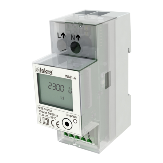
- Page 8 ASIC DESCRIPTION AND OPERATION 1.1 Description of the device The single-phase energy meters WM1-6A, WM1M6A (MID certified) are intended for energy measurements in single-phase electrical power network and can be used in residential, industrial and utility applications. Meters measure energy directly in 2-wire networks according to the principle of fast sampling of voltage and current signals.
- Page 9 ASIC DESCRIPTION AND OPERATION 1.2 Single-phase energy meters application Energy meters have built-in optical (IR) communication port on the side as a standard. Special WM-USB adapter (size 1 DIN module) can easily be attached to it. It can be used for direct communication with a PC to change settings of devices without any communication installed.
- Page 10 Connection shall therefore be performed ONLY by a qualified person using an appropriate equipment. ISKRA, d.o.o. does not take any responsibility regarding the use and connection. If any doubt occurs regarding connection and use in the system which device is intended for, please contact a person who is responsible for such installations.
- Page 11 CONNECTION 2.1 Mounting Singlee-phase electrical energy meter WM1x6A is intended only for DIN-rail mounting. In case of using the stranded wire, the ferrule must be attached before the mounting. Ferrule contact length should be 18 mm. Figure 2: Dimensional drawing and rear connection terminals position User’s Manual...
- Page 12 CONNECTION 2.2 Electrical connection WARNING Wrong or incomplete connection of voltage or other terminals can cause non-operation or damage to the device. To prevent electrical shock and/or equipment damage, disconnect electrical power at the main fuse or circuit breaker before installation or any servicing. ...
- Page 13 CONNECTION Figure 4: Connection diagram for M-BUS option Figure 5: Connection diagram for tariff input option Figure 6: Connection diagram for pulse output and RS485 communication Complete WM1x6A system is assembled with three units: Current and voltage capture unit. ...
- Page 14 CONNECTION Table 1: Survey of communication connection Auxiliary terminal M-Bus Tariff input RS485* *It is recommended to use ferrite bead on communication line RS485 (two turns) to reduce radiated emission. PLEASE NOTE Check labels on the side of the meter to check what modules are built in. User’s Manual...
- Page 15 FIRST STEPS 3 FIRST STEPS Programming a single-phase electrical energy meter WM1x6A is very transparent and user friendly. Numerous settings are organized in groups according to their functionality. In this chapter you will find basic programming steps: ISPLAY OF DEVICE INFO LCD U NTERFACE IMITS...
- Page 16 FIRST STEPS 3.1 Display of device info On LCD measured data are presented. Display scrolls automatically. Displayed quantities and scroll time can be set via communication by MiQen software. Energy meters have LCD display with following layout. Tariff setting for displayed counter/actual tariff (→) Energy import/active power import ...
- Page 17 FIRST STEPS 3.2 LCD User Interface After the electrical connection, the display shows a welcome screen for two seconds then the firmware version for the next two seconds. The following is a measurement screen automatically cycling on the screen, regarding the period that is defined in settings. The cycling period and required measurement could be set factory or in MiQen software.
- Page 18 FIRST STEPS 3.2.1 Energy counters Energy counters are represented as shown on LCD examples bellow (up to 4 resetable counters, letter r representing it). At the top of the screen is settings of energy counter (tariff, import/export/total, active/reactive/apparent), the 8-digit numerical number shows the value of the energy and the letter at the bottom shows actual activity (counting (A)/not counting ( )).
- Page 19 FIRST STEPS Voltage: Reactive power: Apparent power: Power factor: User’s Manual...
- Page 20 FIRST STEPS Power angle: Frequency: 3.2.3 Display menu structure The display menu is entered by holding the push button for more than one second. Blinking of the screen indicates that. Short clicks then move user through the main menu. By holding the button when positioned on certain screen ( e.g. counter menu, set, info, etc…) the Set sub-menu is entered. User’s Manual...
- Page 21 FIRST STEPS 3.2.3.1 Set sub-menu When in set sub-menu, short clicks move user through it, allowing her/him to select a dedicated menu. The screens 3.2 to 3.4 appear only in case the actual option is available on the meter. User’s Manual...
- Page 22 FIRST STEPS 3.2.3.1.1 Reset counters menu Holding button on any of screens 3.1.1 through 3.1.5 resets any of counters or all of them respectively. 3.2.3.1.2 RS485 menu Screen 3.2.1 shows the address of RS485 communication and screen 3.2.2 shows the baud rate. 3.2.3.1.3 M-bus menu Screens 3.3.1 shows the primary address of M-bus communication, screen 3.3.2 shows baud rate and screen 3.3.3 shows the secondary address.
- Page 23 Screen 4.3 shows CRC code and below the number of Firmware upgrades. Screen 4.4 shows CRC of parameters and below the number of times the WM1M6A (MID version) was unlocked. Screen 4.5 shows operating time (days:hour:minute) of WM1-6A. Screen 4.6 shows initial LCD screen with all segments on.
- Page 24 RS485 network. 3.2.5 ZWave inclusion WM1-6A that has a built-in ZW module supports LCD menu that allows inclusion or exclusion into ZWave network. Holding the button for more than 6 seconds, the energy meter will switch to inclusion or exclusion ZWave mode and LCD shows the following menu: Holding button on screen 5.1 include or exclude ZWave from network.
- Page 25 FIRST STEPS 3.3.1 Limit A User can set the ON state of an output A, when the threshold is reached (any from the above specified measured values can be set as a threshold). Likewise the OFF state can be set, when the same measured value falls below the OFF state threshold.
- Page 26 FIRST STEPS Limit A AND Limit B Limit A AND Limit B is a logical operation, which sets the output A AND B ON, when both output A and output B are in ON. Figure below (example 3) shows the example of output A AND B being ON. For clearer picture refer also to output A (example 1) and output B (example 2) figures.
- Page 27 FIRST STEPS Following Modbus registers define Limit function: Address Contents Data Values P. Level LIMIT 40187 Limits enabled None Limit 1 Limit 2 Limit 1 OR Limit 2 Limit 1 AND Limit 2 40188 Display notification None Relay ON Relay OFF 40189 Limit 1: Parameter See OutTypes...
- Page 28 FIRST STEPS 3.4 Freeze counters 3.4.1 Meaning Since WM1-6A energy meter does not support internaly synchronised real-time clock (RTC) for the purpose of simultaneous capture of measurements, the freeze function is implemented. Use is enabled only when the meter is on.
- Page 29 FIRST STEPS 3.4.5 Status register of freeze (41905) The purpose of the status register is to test the reliability of RS485 communication. Enter the broadcast command of different identification codes between 1 to FFFD in the freeze status register (41905). Repeatedly send a different identification code to the freeze status register (41905) in order to increase the reliability of receiving commands.
- Page 30 SETTINGS 4 SETTINGS A setting structure, which is similar to a file structure in an explorer is displayed in the left part of the MiQen setting window. Available settings of that segment are displayed in the right part by clicking any of the stated parameters.
- Page 31 (size 1 DIN module) and MiQen software version 2.0 or higher. 4.2 MiQen software MiQen software is a tool for a complete programming and monitoring of ISKRA measuring instruments, connected to a PC via serial communication or by a special WM-USB adapter. A user-friendly interface consists of five segments: devices management (Connection), instrument settings (Settings), real-time measurements (Measurements), data analysis (Analysis), and software upgrading (Upgrades).
- Page 32 MiQen version 2.1 or higher is required for programming and monitoring WM1x6A. Software installation is stored on a CD as a part of consignment or it can be downloaded from https://www.iskra.eu/en/Iskra-Software/MiQen-Settings-Studio/ PLEASE NOTE MiQen has very intuitive help system. All functions and settings are described in Info window on the bottom of MiQen window.
- Page 33 SETTINGS Set device Modbus address number Each device connected to a network has its unique Modbus address number. In order co communicate with that device an appropriate address number should be set. Factory default Modbus address for all devices is 33. Therefore it is required to change Modbus address number of devices if they are connected in the network so each device will have its unique address number.
- Page 34 The BP password is available in the user support department in ISKRA d.o.o., and is entered instead of the password PL1 or/and PL2. Do not forget to state the device serial number when contacting the personnel in ISKRA, d.o.o..
- Page 35 SETTINGS 4.4.2.1 Counters There are four pairs of counters, which are user configurable. Each counter setting applies to one resetable and one non-resetable counter. User can set Active, Reactive, Apparent Energy, energy flow direction and tariff. In Custom setting there are additional options for measurment in individual quadrants and energy measurement for individual phases.
- Page 36 SETTINGS Figure 15: Measurements in tabular form For further processing of the results of measurements, it is possible to set a recorder ( button) on active device that will record and save selected measurements to MS Excel .csv file format. Figure 17: Measurements Recorder User’s Manual...
- Page 37 SETTINGS 4.6 Data analysis PLEASE NOTE The energy meter WM1x6A do not support data analysis. 4.7 My devices My devices section enables the personal selection of devices. 4.8 Software upgrading MID version does not support software upgrade. Always use the latest version of software, both MiQen and software in the device. The program automatically informs you about available upgrades (device firmware upgrades and MiQen software upgrades) that can be transferred from the web site and used for upgrading.
- Page 38 MEASUREMENTS 5 MEASUREMENTS The WM1-6A is bidirectional energy meter measures voltage and current. From which it is able to calculate two quantities, imported and exported energy. The WM1-6A energy meter performs measurements with a sampling frequency equal to 3906,25 Hz.
- Page 39 MEASUREMENTS 5.1 Introduction 5.1.1 Online measurements Online measurements are available on display or can be monitored with setting and monitoring software MiQen. Readings on display are performed continuously with refresh time dependent on set average interval whereas rate of readings monitored with MiQen is fixed and refreshed approx. each second. Figure 27: Online measurements in tabelaric form User’s Manual...
- Page 40 MEASUREMENTS 5.2 Selection of available quantities Microprocesor calculates the RMS voltage, RMS current, active, reactive and apparent power, power factor, power angle, first harmonic of voltage, first harmonic of current, THD of voltage and THD of current. Complete selection of available online measuring quantities is shown in a table below. Meas.
- Page 41 MEASUREMENTS 5.3 Calculation and display of measurements This chapter deals with capture, calculation and display of all supported measurement quantities. For more information about display presentation see chapter 3.2 LCD User Interface. Only the most important equations are described; however, all of them are shown in a chapter APPENDIX C: EQUATIONS with additional descriptions and explanations.
- Page 42 MEASUREMENTS 5.3.4 Power factor and power angle PF or distortion power factor is calculated as the quotient of active and apparent power for each phase separately and total power angle. It is called distortion power factor since true (distorted) signals are using in equation (all equations are presented in chapter APPENDIX C: EQUATIONS).
- Page 43 TECHNICAL DATA 6 TECHNICAL DATA In following chapter all technical data regarding operation of a single-phase electrical energy meter is presented. CCURACY ECHANICAL CHARACTERISTICS OF INPUT LECTRICAL CHARACTERISTICS OF INPUT AFETY AND AMBIENT CONDITIONS User’s Manual...
- Page 44 TECHNICAL DATA 6.1 Accuracy Measured values Accuracy class Active energy: class 1 EN 62053-21 class B EN 50470-3 ±1.5% from �� to �� ������ ���� ±1% from �� to �� ���� ������ Reactive energy: class 2 EN 62053-23 ±2.5% from �� to ��...
- Page 45 TECHNICAL DATA Minimum measuring time: 10 s User’s Manual...
- Page 46 TECHNICAL DATA Pulse output (option) Pulse rate: 1000 imp/kWh Pulse duration: 32 ms ± 2 ms Rated voltage DC: 27 V max Switched current 27 mA max Standard: EN 62053-31 (A&B) M-BUS Serial communication (option) Type: M-BUS Speed: 300 bit/s to 9600 bit/s (default 2400 bit/s) Protocol: M-BUS Primary address:...
- Page 47 TECHNICAL DATA 6.4 Safety and ambient conditions According to standards for indoor active energy meters. Temperature and climatic condition according to EN 62052-11. Dust/water protection: IP50 (For IP51 it should be installed in appropriate cabinet.) Operating temperature: -25 °C - +55 °C (non-condensig humudity) Storage temperature: -40 °C - + 70 °C Enclosure:...
- Page 48 TECHNICAL DATA 6.5 EU DIRECTIVES CONFORMITY EU Directive on Measuring Instruments 2014/32/EU EU Directive on EMC 2014/30/EU EU Directive on Low Voltage 2014/35/EU EU Directive WEEE 2002/96/EC 6.6 Dimensions 6.6.1 Dimensional drawing Construction Appearance All dimensions are in mm Dimensions User’s Manual...
- Page 49 Abbreviations are explained within the text where they appear the first time. Most common abbreviations and expressions are explained in the following table: Term Explanation MODBUS / DNP3 Industrial protocol for data transmission MiQen Setting Software for ISKRA instruments Pulse input module Alternating quantity Infrared (optical) communication Pt1000 Temperature sensor Root Mean Square...
- Page 50 8 APPENDICES 8.1 APPENDIX A: MODBUS communication protocol Modbus protocol enables operation of device on Modbus networks. For WM1-6A\WM1M6A with serial communication the Modbus protocol enables multi drop communication via RS485 communication. Modbus protocol is a widely supported open interconnect originally designed by Modicon.
- Page 51 The tables below represent the complete set of MODBUS register map. SETTINGS Contents Data Values / Dependencies Address Input Registers READ ONLY INFO 30000 Device group 30001 30008 Model Number T_Str16 WM1-6A Energy 30009 30012 Serial Number T_Str8 WM###### 30013 Software Reference 100=1.00 30014 Hardware Reference T_Str2 A (B,C,D…) 30015...
- Page 52 APPENDICES Contents Data Values / Dependencies Address Input Registers 30080 FW upgrade counter 30096 CheckSum Parameters 30097 CheckSum Firmware 30098 Active Communication Port COM1 30099 Modbus Max. Register Read at Once 30101 Phase valid measurement Bit 0 Invalid measurement phase 1 Bit 1 Invalid measurement phase 2 Bit 2...
- Page 53 APPENDICES Contents Data Values / Dependencies Address Input Registers ACTUAL MEASUREMENTS 30105 30106 Frequency 30107 30108 30126 30127 30140 30141 Active Power Total (Pt) 30148 30149 Reactive Power Total (Qt) 30156 30157 Apparent Power Total (St) 30164 30165 Power Factor Total (PFt) 30172 Power Angle Total(atan2(Pt,Qt))
- Page 54 APPENDICES Contents Data Values / Dependencies Address Input Registers ENERGY 30400 Error register No Error Bit 0 Error Parameter CRC Bit 1 Error Firmware CRC Bit 2 MID version is not locked 30401 Energy Counter 1 Exponent (resettable) 30402 Energy Counter 2 Exponent (resettable) 30403 Energy Counter 3 Exponent (resettable) 30404...
- Page 55 APPENDICES Address Data Values Contents Level RAM logger 36000 Measurement parameter See OutTypes 36001 Time interval minutes 36002 Number of valid results 36003 Time stamp of last minutes since midnight result (<0 if no time) 36004 36131 Logger table (newest to Normalised values oldest) ACTUAL MEASUREMENTS...
- Page 56 APPENDICES Address Contents Data Values Level 40013 Reset command register 1 Bit-0 Reset counter 1 Bit-1 Reset counter 2 Bit-2 Reset counter 3 Bit-3 Reset counter 4 Reset alarm output relay Bit-4 40015 external relay command action 40016 Load control Output state 40017...
- Page 57 APPENDICES Address Data Values Contents Level Reverse Energy flow 40151 CT connection direction (Fixed) 40173 LCD Mode Manual Cycling 40174 LCD cycling period Seconds 40184 LCD parameters Bit 0 Counter 1 (Always) 65535 Bit 1 Counter 2 Bit 2 Counter 3 Bit 3 Counter 4 Bit 4...
- Page 58 APPENDICES COMMUNICATION 40202 Port 1: Device Address (Modbus) 40203 Port 1: Baud Rate Baud rate 1200 Baud rate 2400 Baud rate 4800 Baud rate 9600 Baud rate 19200 40204 Port 1: Stop Bit 1 Stop bit 2 Stop bits 40205 Port 1: Parity No parity Odd parity...
- Page 59 APPENDICES Address Contents Data Values Level ENERGY 40401 Active Tariff Tariff input 1..2 Tariff 1..2 40421 Energy Counter Active Power Parameter Reactive Power Apparent Power 40422 Energy Counter Bit-0 Quadrant I Enabled Configuration Bit-1 Quadrant II Enabled Bit-2 Quadrant III Enabled Bit-3 Quadrant IIII Enabled Bit-4...
- Page 60 APPENDICES Counter freeze 41901 Auto freeze interval [minutes] 41902 time to freeze [s] 41903 41904 time from freeze [s] 41905 Freeze status 41906 Current Active Tariff 41907 41908 Energy Counter 1 (resetable) 41909 41910 Energy Counter 2 (resetable) 41911 41912 Energy Counter 3 (resetable) 41913 41914...
- Page 61 APPENDICES Type Value / Bit Mask Description Unsigned Measurement (32 bit) bits # 31..24 Decade Exponent(Signed 8 bit) bits # 23..00 Binary Unsigned Value (24 bit) Example: 123456*10 stored as FD01 E240 (16) Signed Measurement (32 bit) bits # 31..24 Decade Exponent (Signed 8 bit) bits # 23..00 Binary Signed value (24 bit)
- Page 62 APPENDICES Type Value / Bit Mask Description T_Time Time and Date (64 bit) bits # 63..56 1/100s 00 - 99 (BCD) bits # 55..48 Seconds 00 - 59 (BCD) bits # 47..40 Minutes 00 - 59 (BCD) bits # 39..32 Hours 00 - 24 (BCD) bits # 31..24 Day of month 01 - 31 (BCD)
- Page 63 WM1-6A confirms correct receipt by transmitting of the Read-out Data. If the Short Telegram has not been received correctly; no Data will be transmitted by the M-BUS WM1-6A. The Read-out Data are sent within 35 ms – 75 ms from receipt of the Short Telegram by the M-BUS Meter (fom more infomations see section M-Bus telegrams).
- Page 64 APPENDICES M-Bus Telegram Total Energy counters 0, 1, 2, 3 Energy counters could represent: +/- active energy, +/-reactive energy or apparent energy and one of 4-th tariff. DIFE DIFE VIFE VIFE VIFE DATA xx.xx.xx.xx none none none none None none none none none...
- Page 65 APPENDICES Voltages (V) Voltage as 32 bit x 10 (7-9) DIFE VIFE VIFE VIFE DATA xx.xx.xx.xx 8.3 APPENDIX C: Equations Definitions of symbols Symbol Definition Phase, f is allways equal 1. Phase voltage (U Total number of samples in a period Sample number (0 ≤...
- Page 66 APPENDICES Apparent power − phase voltage − phase current Reactive power − apparent power SignQ − active power Reactive power by phases (displacement method) N − a number of samples in a period ...
- Page 67 Published by Iskra, d.o.o. • Subject to change without notice • Version 1.01 December 2021 • EN K22.433.913...
Need help?
Do you have a question about the WM1-6A and is the answer not in the manual?
Questions and answers