
Related Manuals for Iskra IE14-S


Summary of Contents for Iskra IE14-S
- Page 1 Series of single phase meters IMPACT- IE14: IE14-S IE14MS IE14MN IE14MM IE14MD IE14MDC September 2020 • Version 1.09 User’s Manual...
- Page 2 Single-phase electrical energy meter IMPACT-IE14 User’s and Installation manual User’s Manual...
- Page 3 ,and maintained by qualified personnel only. ISKRA Company assumes no responsibility in connection with the installation and use of the product. If there is any doubt regarding the installation and use of the system in which the device is used for measuring or supervision, please contact a person who is responsible for the installation of such a system.
- Page 4 Used symbols on devices’ housing and labels SYMBOL EXPLANATION Single phase connection. Double insulation in compliance with the EN 61010−1: 2010 standard. WARNING Indicates situations where careful reading of this manual is required and following requested steps to avoid potential injury is advised. NFC communication.
-
Page 5: Table Of Contents
ASIC DESCRIPTION AND OPERATION Table of contents BASIC DESCRIPTION AND OPERATION ESCRIPTION OF THE DEVICE INGLE PHASE ENERGY METERS APPLICATION AIN FEATURES IMPACT-IE14 YPES OF ENERGY METERS CONNECTION OUNTING LECTRICAL CONNECTION FIRST STEPS ISPLAY OF DEVICE INFO LCD U NTERFACE REEZE COUNTERS SETTINGS NTRODUCTION... - Page 6 ASIC DESCRIPTION AND OPERATION CCURACY ECHANICAL CHARACTERISTICS OF INPUT LECTRICAL CHARACTERISTICS OF INPUT AFETY AND AMBIENT CONDITIONS EU DIRECTIVES CONFORMITY IMENSIONS ABBREVIATION/GLOSSARY APPENDICES DVANCED NCRYPTION TANDARD APPENDIX A: MODBUS COMMUNICATION PROTOCOL APPENDIX B: M-B APPENDIX C: OBIS CODE APPENDIX D: E QUATIONS User’s Manual...
-
Page 7: Basic Description And Operation
ASIC DESCRIPTION AND OPERATION 1 BASIC DESCRIPTION AND OPERATION The following chapter presents basic information about a IE14 single-phase energy meter required to understand its purpose, applicability, and basic features connected to its operation. In this chapter, you will find: Description of the device Appearance Single-phase energy meters application... -
Page 8: Description Of The Device
ASIC DESCRIPTION AND OPERATION 1.1 Description of the device The IE14 single-phase energy meters are intended for energy measurements in single-phase electrical power networks and can be used in residential, industrial, and utility applications. Meters measure energy directly in 2-wire networks according to the principle of fast sampling of voltage and current signals. -
Page 9: Single-Phase Energy Meters Application
Meter has an optional built-in optical (IR) communication port on the side. It can be used for controlling Bistable switch – BICOM or in combination with SG smart gateway (more info about BICOM and SG can be found on https://www.iskra.eu/. Meter can be equipped: ... - Page 10 ASIC DESCRIPTION AND OPERATION voltage, current, frequency, power factor, power angle, active tariff (option), THD of voltage, THD of current. Pulse output according to EN 62053-31 (option). RS485 (Modbus) Serial communication (option). M-Bus Serial communication (option). NFC communication for easy setting and downloading meter data via mobile app.
-
Page 11: Types Of Impact-Ie14 Energy Meters
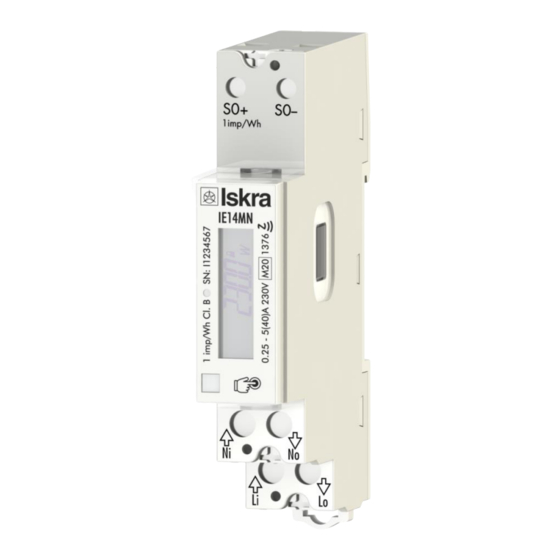
CONNECTION 1.4 Types of IMPACT-IE14 energy meters 022433925000 IE14-S Single phase energy meter 40 A, S0, without capacitive touch button 022433925100 IE14MS Single phase energy meter 40 A, S0, MID 022433925200 IE14MN Single phase energy meter 40 A, S0, IR, NFC, MID... -
Page 12: Connection
ONLY by a qualified person using appropriate equipment. ISKRA, d.o.o. does not take any responsibility regarding the use and connection. If any doubt occurs regarding connection and uses in the system which device is intended for, please contact a person who is responsible for such installations. -
Page 13: Mounting
CONNECTION 2.1 Mounting The IE14 single-phase electrical energy meter is intended only for DIN-rail mounting. In the case of using the stranded wire, the ferrule must be attached before the mounting. The ferrule contact length should be 12 mm. 2.2 Electrical connection WARNING Wrong or incomplete connection of voltage or other terminals can cause non-operation or damage to the device. - Page 14 CONNECTION Figure 2: Electrical diagram 230 V Mark Meaning Line input Neutral input Line output Neutral output Table 2: Marks of inputs and outputs. User’s Manual...
- Page 15 CONNECTION Figure 3: Connection diagram for pulse output Figure 4: Connection diagram for M-Bus option Figure 5: Connection diagram for RS485 communication 2.2.1 Communication connection There are multiple options for communication available for interaction with the outside world: IR communication module (option) using the MODBUS. It can be used for setting and testing the meter using a USB adapter.
- Page 16 CONNECTION Auxiliary terminal Pulse output M-Bus RS485 *It is intended to be used for shielding for RS485. Table 3: Survey of communication connection PLEASE NOTE Check connection diagram on the side of the meter to check what modules are built in. User’s Manual...
-
Page 17: First Steps
FIRST STEPS 3 FIRST STEPS Programming an IE14 single phase energy meter is very transparent and user friendly. Numerous settings are organized in groups according to their functionality. In this chapter, you will find basic programming steps: Display of device info LCD User Interface Freeze counters User’s Manual... -
Page 18: Display Of Device Info
FIRST STEPS 3.1 Display of device info Measured data is presented on LCD. Display scrolls automatically. Displayed quantities and scroll time can be set via communication by MiQen software, or via mobile app using NFC. Energy meters have LCD display with the following layout: Actual Value Non resettable (MID) energy register. -
Page 19: Lcd User Interface
FIRST STEPS 3.2 LCD User Interface After the electrical connection, the display shows a segment check screen, software version screen, and check sum screen in a period of five seconds. The following is automatic cycling of measurements which consists of energy counters and actual measured values. The period is defined in settings. The cycling period and required measurement could be set via capacity touch, MiQen software, or mobile app using NFC. - Page 20 FIRST STEPS 3.2.1 Capacity touch selfcalibration process In a reported fixed 64s interval the average, minimum, and maximum value of the capacity touch sensor is calculated. If the conditions are stable (without interruptions) then the average value of the capacity touch sensor is used as a reference value. If the new reference value deviates sufficiently from the permanently stored value, it is permanently saved.
- Page 21 FIRST STEPS (Abs(Q1+Q4) – abs(Q2+Q3)) Active energy Q1– all tariffs 17.8.0 A. .0 Active energy Q2– all tariffs 18.8.0 A. .0 Active energy Q3– all tariffs 19.8.0 A. .0 Active energy Q4– all tariffs 20.8.0 A. .0 Reactive energy – Q1+Q2 - all tariffs 3.8.0 r.I.0 Reactive energy –...
- Page 22 FIRST STEPS 3.2.3 Actual measured quantities The number on the screen shows the actual value of the measured quantity (P-W, Q-var, S, PF, U, f, and I). There is the direction of active energy flow (import/export = (/)) and reactance (inductive/capacitive = L/C) on the screen as well.
- Page 23 FIRST STEPS Power angle: THD-U: THD-I: 3.2.4 Initial display menu structure The display menu is entered by touching the capacitive button for more than one second. The blinking of the screen indicates that. Short touches to move through the main menu. If the capacitive button is not used for more than one minute, the cycling mode starts automatically.
- Page 24 FIRST STEPS Software Check sum: A checksum is a small-sized datum derived from a block of digital data for the purpose of detecting errors that may have been introduced during its transmission or storage. Screen 1: – Measurement module Check-sum Screen 2: –...
- Page 25 FIRST STEPS 3.2.4.3 Set menu When in set menu, short touches move user through it, allowing her/him to select a dedicated menu. 3.2.4.3.1 Set sub-menus Led test mode (Led tSt): This function shall be used only for testing purposes during type testing and metrological verification of the meters. Test modes: Normal –...
- Page 26 FIRST STEPS Communication menu: (when in COMM menu, short touches move user through it): Communication menu is available at M-bus and RS485 option (IE14MM and IE14MD) and can be used for setting communication parameters (communication addresses, baud rate, parity and stop bits) M-bus setting menu: If one stops using short touches on a certain screen, the screen with the parameter value is shown and it starts cycling automatically.
-
Page 27: Freeze Counters
FIRST STEPS 3.2.4.4 Reset menu When in the reset menu, short touches move the user through it, allowing her/him to select a dedicated menu. With the long touch, all counters or a single counter can be chosen. Reset counter E05: For final execution, additional confirmation of reset is necessary. - Page 28 FIRST STEPS 3.3.3 Time to freeze register (41902) The purpose of the time to freeze register is to freeze all energy meters simultaneously. Set the number of times to freeze register (41902), the value of appropriate time (in seconds) before the time of the freeze, and time of the freeze.
- Page 29 FIRST STEPS PLEASE NOTE Please do not use the values 0000, FFFF, or FFFE. The 0000 is reserved to start the meter when connected to the power supply. The freeze function is performed. The FFFF is reserved to trigger the freezing function automatically (same as the time to freeze register 41902). The FFFE is reserved for the auto interval freeze.
-
Page 30: Settings
SETTINGS 4 SETTINGS A setting structure, which is similar to a file structure in an explorer is displayed in the left part of the MiQen setting window. Available settings of that segment are displayed in the right part by clicking any of the stated parameters. -
Page 31: Introduction
(size 1 DIN module) and MiQen software version 2.0 or higher. 4.2 MiQen software MiQen software is a tool for complete programming and monitoring of ISKRA measuring instruments, connected to a PC via serial communication or by a special IR-USB adapter (only for devices with IR communication). -
Page 32: Devices Management
SETTINGS MiQen version 2.1 or higher is required for programming and monitoring IE14. Software installation can be downloaded from https://www.iskra.eu/en/Iskra-Software/MiQen-Settings-Studio/ PLEASE NOTE MiQen has very intuitive help system. All functions and settings are described in Info window on the bottom of MiQen window. -
Page 33: Device Settings
SETTINGS Set device Modbus address number Each device connected to a network has its unique Modbus address number. In order to communicate with that device an appropriate address number should be set. Figure 10: Address number The factory default the Modbus address for all devices is 33. Therefore it is required to change Modbus address number of devices if they are connected in the network so each device will have its unique address number. - Page 34 SETTINGS Average interval for measurements (sec): the averaging interval defines a refresh rate of measurements on display or communication. It is also used for actual alarm value calculation for alarm triggering. Figure 13: Average interval for measurements window Mode defines whether displayed values automatically cycle between different measurands or display only one measurement.
- Page 35 Figure 15: Cycling period window Displayed measurements – Counters: sets the counters displayed at the display. A user can select them on the drop-down menu (low-cost version (IE14-S) only shows counter 1): Figure 16: Set of displayed measurements User’s Manual...
- Page 36 SETTINGS Displayed measurements – Others: sets the measurements at the startup display. Figure 17: Displayed measurements window Backlight intensity: defines the visibility and legibility of a display. Display settings shall be defined in compliance with the conditions in which they will be monitored. Economizing mode switches off backlight according to the set time of inactivity.
- Page 37 SETTINGS Saving mode (min): defines the time in minutes for the instrument to get into energy-saving mode (backlight off). Enter value 0 if you don’t want to use energy-saving mode. … Figure 19: Saving mode window User’s Manual...
- Page 38 A backup password >BP is used if passwords at level 2 >PL2 has been forgotten, and it is different for each device. For meters without communication (IE14-S), the backup password code (which you can access in the backup code menu; 3.2.4.2.1) is enough. For other meters, there is a serial number that has to be stated to the user support department in Iskra d.o.o.
- Page 39 SETTINGS 4.4.1.1.2 Generating passwords Enter L1 password. Example: BBBB Figure 20: Password Level 1 window Enter L2 password. Example: CCCC Figure 21: Password Level 2 window Right click on the mouse and execute “Download settings”. Figure 22: Download settings window After the execution, the passwords are entered.
- Page 40 SETTINGS 4.4.1.1.3 Operation test for passwords (example for L1) Go to the “Reset window”. Choose the option “Reset energy counters”. Figure 23: Reset window Mark the counter you want to reset. Figure 24: Reset energy counters window Click “OK”. Right click on the mouse and execute “Download settings”. Figure 25: Download settings window Then L1 password is required.
- Page 41 SETTINGS 4.4.1.1.4 Wrong password entry In the case of a wrong L1 or L2 password entry, a note appears stating that the password is incorrect. Figure 27: Wrong password entry window Another entry can be carried out after 5 s. if you enter the L2 password in this field where the L1 password is required, the action will run without disruption.
- Page 42 SETTINGS Then type the CCCC password (for example). Figure 31: Password 2 entry window L2 password is removed, and L1 also after that. Figure 32: Download complete window Both password positions are now set to not set. PLEASE NOTE A factory set password is "AAAA" at both access levels >PL1 and PL2. This password does not limit access.
- Page 43 SETTINGS 4.4.2 Energy Active Tariff setting is not applicable as no tariff input is available at IE14 meter. For meters with RS485 communication the resettable non-MID counters C1 to C8 can be parametrised for tariffs T1 to T4 and the tariff can be changed by writing the tariff value to the MODBUS register 40030 using system software (not supported in MiQen software).
- Page 44 4.4.3.1 IR relay IR Relay module supports control of ISKRA bistable switch BICOMxxx-WM1 via IR port. IR Relay operating mode defines how IE14 controls external bistable switch BICOM via propriety IR communication. Available modes are: Not connected, Manual, and Limit control. The Preset is Not connected.
- Page 45 SETTINGS Figure 35: Pulse output window 4.4.4 Limits IE14 has a built-in limit function which can control the bistable relay using IR communication or optional S0 output. They are divided into 3 groups (1, 2, E), each having 4 limits. Each group of limits has some common settings applicable to all limits within this group.
- Page 46 SETTINGS Figure 37: Limit settings window 4.4.5 Programmable logic Figure 38: Programmable logic window 4.4.5.1 Logical function 1 & Logical function 2 Basic logical functions are: AND, OR, XOR, NOT, NAND, NOR and XNOR. IE14 supports AND/OR logical functions. Figure 39: Logical function window User’s Manual...
-
Page 47: Real-Time Measurements
SETTINGS Logical function - Select logical function over existing logical inputs: Figure 40: Logical function selection window 4.5 Real-time measurements Measurements can be seen ONLINE when the device is connected to aux. power supply and is communicating with MiQen. When the device is not connected it is possible to see OFFLINE measurement simulation. - Page 48 SETTINGS Figure 42: Energy in tabular form MiQen shows Check Sum Status in the scope of Energy measurement display as a binary value of Check Sum Status register 30400. For more information, see chapter 3.2.3.2.1. Figure 43: Limits in tabular form User’s Manual...
- Page 49 SETTINGS Figure 44: Measurements in tabular form For further processing of the results of measurements, it is possible to set a recorder ( button) on an active device that will record and save selected measurements to MS Excel .csv file format.
-
Page 50: Data Analysis
SETTINGS RAM logger Actual measurements in the Graphic view show a vector diagram and a graph of 96 average 15 minutes values of active power, which represents the values for one day. The values are taken from the set of 128 average active power values of the RAM logger. It is not stored in the non-volatile memory, so it is lost at power down. - Page 51 SETTINGS PLEASE NOTE MiQen cannot be used for the execution of firmware upgrades of devices. It only informs that a new version is available and offers a link to download it from the server. Software for the execution of firmware upgrades is included in the downloaded zip file together with the upgrade file, upgrade procedure, description and revision history.
-
Page 52: Nfc Settings
MID certified (energy registers can be reset) the parameters of the energy registres can also be changed. The advantage of NFC implemented functionality on Iskra d.o.o./electricity meters is that in the event of a power down, it remembers all the last measured values, which can be read via NFC. -
Page 53: Measurements
MEASUREMENTS 5 MEASUREMENTS The IE14 is a bidirectional energy meter that samples voltage and current. From that, it can calculate all measuring quantities. The IE14 energy meter performs measurements with a sampling frequency equal to 3906,25 Hz. Introduction Selection of available quantities Calculation and display of measurements User’s Manual... -
Page 54: Introduction
MEASUREMENTS 5.1 Introduction 5.1.1 Online measurements Online measurements are available on display or can be monitored with setting and monitoring software MiQen. Readings on display are performed continuously with refresh time dependent on set average interval whereas the rate of readings monitored with MiQen is fixed and refreshed approximately every second. -
Page 55: Selection Of Available Quantities
MEASUREMENTS 5.2 Selection of available quantities Microprocessor calculates the RMS voltage, RMS current, active, reactive, and apparent power, power factor, power angle, first harmonic of voltage, first harmonic of current, THD of voltage, and THD of current. A complete selection of available online measuring quantities is shown in a table below. Meas. -
Page 56: Calculation And Display Of Measurements
MEASUREMENTS 5.3 Calculation and display of measurements This chapter deals with capture, calculation, and display of all supported measurement quantities. For more information about display presentation see chapter 3.2. Only the most important equations are described; however, all of them are shown in chapter APPENDIX C: EQUATIONS with additional descriptions and explanations. - Page 57 MEASUREMENTS 5.3.4 Power factor and power angle The power factor is calculated as the quotient of active and apparent power. The power angle is the angle between the active and reactive power. 5.3.5 Frequency Network frequency is calculated from periods of the measured voltage. The instrument uses a synchronization method, which is highly immune to harmonic disturbances.
-
Page 58: Digital Signature (Valid Only For Ie14Mdc)
DIGITAL SIGNATURE ( IE14MDC) VALID ONLY FOR 6 DIGITAL SIGNATURE (VALID ONLY FOR IE14MDC) Introduction Digital signing procedure Energy meter cryptographic functions explanation Consumption measuring and digital signing procedure Crypto Register Definitions Power loss behaviour Unexpected reset behaviour 64 User’s Manual... -
Page 59: Introduction
DIGITAL SIGNATURE ( IE14MDC) VALID ONLY FOR 6.1 Introduction Energy meter supports digital signing of billing information to ensure integrity of data for end customer. All digital signing procedures are HW based with dedicated crypto chip, which supports ECDSA FIPS186-3 Elliptic Curve Digital Signature. Energy meter supports MODBUS over RS485 for communication with EV control unit. -
Page 60: Energy Meter Cryptographic Functions Explanation
DIGITAL SIGNATURE ( IE14MDC) VALID ONLY FOR 6.3 Energy meter cryptographic functions explanation Energy meter has HW based cryptographic unit for digital signing of billing dataset. 6.3.1 Generation of private/public key par This is one-time procedure made at production of energy meter. Generation of key pair is HW based with dedicated crypto chip. -
Page 61: Consumption Measuring And Digital Signing Procedure
DIGITAL SIGNATURE ( IE14MDC) VALID ONLY FOR 6.4 Consumption measuring digital signing procedure EV charger control unit must use following procedure to measure charging consumption and sign billing dataset: Set time, time zone, signature format Enter billing dataset Enter dataset size Send Begin command Send intermediate reading commands (optional) Send fiscal reading (optional) - Page 62 DIGITAL SIGNATURE ( IE14MDC) VALID ONLY FOR 6.5.2 Cryptographic control registers MODBUS Size in Access Type Description Address bytes 47051 Command Register 47052 Signature Status Register 47053 Time zone Offset 47054 - 47055 Date and Time Synchronization 47056 Input Message Length 47057 Output Message Length 47058...
- Page 63 DIGITAL SIGNATURE ( IE14MDC) VALID ONLY FOR 6.5.3 Signature status register (47052) Value Description Not initialised Idle Signature in progress Signature OK Invalid date time CheckSum error Invalid command Invalid state Invalid measurement Test mode error Verify state error Signature state error Keypair generation Error SHA failed Init failed...
- Page 64 DIGITAL SIGNATURE ( IE14MDC) VALID ONLY FOR 6.5.4.2 Time status Control unit must also set the status of clock in register 47071. 6.5.4.3 Time status timeout Clock status changes to Unsynchronized after timeout (in minutes), which is set in register 47072. 6.5.4.4 Time zone Write offset (in minutes) from UTC time to 47053.
- Page 65 DIGITAL SIGNATURE ( IE14MDC) VALID ONLY FOR 6.5.6 Signature algorithm Energy meter currently supports only ECDSA-secp256r1-SHA256 algorithm. Register 47060: Value Signature format Without signature ECDSA-secp256r1-SHA256 Table 13: Signature algorithm. 6.5.7 Entering billing dataset Dataset register is at MODBUS address 47100. Only 120 MODBUS registers (240 bytes) can be entered in one write command.
- Page 66 DIGITAL SIGNATURE ( IE14MDC) VALID ONLY FOR Signature process starts after every command. Control unit can read out signed dataset with current time and energy meter value reading. Meter stores one value (timestamp and counter value) for each command. Registers are defined in measurements table (0).
- Page 67 "GI":"Gateway 1", "GS":"123456789", "PG":"", "MV":"", "MM":"", "MS":"", "MF": "", "IS":true, "IF":[ "RFID_PLAIN", "OCPP_RS_TLS" "IT":"ISO14443", "ID":"1F2D3A4F5506C7", "CT":"EVSEID", "CI":"", "RD":[] Fields highlighted in green are mandatory. Energy meter fills following values: PG:”T<signature counter>” or “F<fiscal counter>” for fiscal readings MV:“Iskra” MM:”IE14” User’s Manual...
- Page 68 DIGITAL SIGNATURE ( IE14MDC) VALID ONLY FOR MS:”meter serial number” MF:”meter firmware version” RD: meter generates complete array of readings data Example of modified dataset: "FV":"1.0", "GI":"Gateway 1", "GS":"123456789", "PG":"T82212", "MV":"Iskra", "MM":"IE14", "MS":"18230001", "MF":"0.21", "IS":true, "IF":[], "IT":"NONE", "ID":"", "CT":"", "CI":"", "RD":[ "TM":"2019-11-11T13:22:28,000+0000 S",...
- Page 69 DIGITAL SIGNATURE ( IE14MDC) VALID ONLY FOR 6.5.16 Measurements table Control unit can check measurements and statuses during the charging process 47000 Measurement status 0 Idle 1 Active 2 Active after power failure 3 Active after reset 47001 47002 Duration Seconds 47003 47004 Consumption T_32U...
-
Page 70: Power Loss Behaviour
DIGITAL SIGNATURE ( IE14MDC) VALID ONLY FOR 6.5.17 Input / Output Data Table 47100 47611 Input Message (JSON/Binary) 47612 48123 Output Message (JSON) 48124 48155 Public Key (raw) 48156 48187 Signature (raw) 48188 48315 Signature ASN.1 48316 Binary Output Message Lenght 48317 Binary Output Message Table 16: Input / Output data table. -
Page 71: Technical Data
TECHNICAL DATA 7 TECHNICAL DATA In following chapter all technical data regarding operation of a single-phase electrical energy meter is presented. Accuracy Mechanical characteristics of input Electrical characteristics of input Safety and ambient conditions User’s Manual... -
Page 72: Accuracy
TECHNICAL DATA 7.1 Accuracy Measured values Accuracy class Active energy: class 1 EN 62053-21 class B EN 50470-3 ±1.5% from �� to �� ������ ���� ±1% from �� to �� ���� ������ Reactive energy: class 2 EN 62053-23 ±2.5% from �� to ��... -
Page 73: Electrical Characteristics Of Input
TECHNICAL DATA 7.3 Electrical characteristics of input Inputs and outputs Type (connection): single-phase (1b) Measuring input Reference current (�� ������ Maximum current (�� 40 A ������ Minimum current (�� 0.25 A ������ Transitional current (�� 0.5 A ���� Starting current (�� 20 mA ����... - Page 74 TECHNICAL DATA Pulse output (option) Type: Optocoupler open collector switch Pulse rate: 1000 imp/kWh (test mode only) Pulse duration: 32 ms ± 2 ms Rated voltage DC: 27 V max Switched current 27 mA max Standard: EN 62053-31 (A&B) M-Bus Serial communication (option) Type: M-Bus Speed:...
-
Page 75: Safety And Ambient Conditions
Touch by fingers protection IP20 Operating temperature: -25 °C - +55 °C (non-condensing humidity) – IE14-S, IE14MS, IE14MN and IE14MM -25 °C…+70 °C (non-condensig humudity) – IE14MD and IE14MDC (optional temperature range also -25 °C - +55 °C) Storage temperature: -30 °C…+ 70 °C... -
Page 76: Eu Directives Conformity
TECHNICAL DATA 7.5 EU DIRECTIVES CONFORMITY EU Directive on Measuring Instruments 2014/32/EU EU Directive on EMC 2014/30/EU EU Directive on Low Voltage 2014/35/EU EC Directive WEEE 2002/96/EC EU Directive RED 2014/53/EU 7.6 Dimensions 7.6.1 Dimensional drawing Construction Appearance All dimensions are in mm Dimensions User’s Manual... -
Page 77: Abbreviation/Glossary
Abbreviations are explained within the text where they appear the first time. Most common abbreviations and expressions are explained in the following table: Term Explanation MODBUS / DNP3 Industrial protocol for data transmission MiQen Setting Software for ISKRA instruments Pulse input module Alternating current Infrared (optical) communication Root Mean Square Pulse output Power angle (between current and voltage) -
Page 78: Appendices
APPENDICES 9 APPENDICES PLEASE NOTE This chapter is a subject of change. 9.1 Advanced Encryption Standard 9.2 APPENDIX A: MODBUS communication protocol Modbus protocol enables operation of device on Modbus networks. For IE14(M)\IE1X(M) with serial communication the Modbus protocol enables multi drop communication via RS485 communication. Modbus protocol is a widely supported open interconnect originally designed by Modicon. - Page 79 APPENDICES Request Frame Starting Register Register Count Slave Address Function Code Response Frame Register Data Slave Address Function Code Byte Count HI LO HI LO FE 00 59 96 Request- response cycle example Address number of slave: 21 Function code: 04 30000 ...
-
Page 80: Appendix B: M-Bus
Secondary Address (UD) consists of: Identification Number: 00000000 – 99999999 8-digit Secondary Address number Manufacturer’s Code: 73 26 2 Byte Company Constant (Iskra = “73 26”) Version Number: 01 – FF 1 Byte Medium: 02 1 Byte Constant Electricit Reset, Restart M-Bus MC350 via Primary/Secondary Address (SND_UD) This Telegram reset/restarts M-Bus MC350. - Page 81 APPENDICES M-Bus Telegram Total Energy counters 0, 1, 2, 3 Energy counters could represent: +/- active energy, +/-reactive energy or apparent energy and one of 4-th tariff. DIFE DIFE VIFE VIFE VIFE DATA xx.xx.xx.xx none none none none None none none none none...
-
Page 82: Appendix C: Obis Code
APPENDICES Voltages (V) (7-9) Voltage as 32 bit x 10 DIFE VIFE VIFE VIFE DATA xx.xx.xx.xx 9.4 APPENDIX C: OBIS CODE OBIS code Description Active energy registers: 1.8.0 Positive active energy (A+) total [kWh] 1.8.1 Positive active energy (A+) in tariff T1 [kWh] 1.8.2 Positive active energy (A+) in tariff T2 [kWh] 1.8.3... -
Page 83: Appendix D: Equations
APPENDICES 7.8.2 Exported inductive reactive energy in 3-rd quadrant (Q3) in tariff T2 [kvarh] 7.8.3 Exported inductive reactive energy in 3-rd quadrant (Q3) in tariff T3 [kvarh] 7.8.4 Exported inductive reactive energy in 3-rd quadrant (Q3) in tariff T4 [kvarh] 8.8.0 Exported capacitive reactive energy in 4-th quadrant (Q4) total [kvarh] 8.8.1... - Page 84 APPENDICES φ ∈ [ 0° − 180° ] → SignQ ( φ ) = +1 Q − reactive power φ ∈ [ 180° − 360° ] → SignQ ( φ ) = −1 − power angle Apparent power �� = �� ∙...
- Page 85 Published by Iskra, d.o.o. • Subject to change without notice • Version 1.09 September 2020 • EN K22.433.925...
Need help?
Do you have a question about the IE14-S and is the answer not in the manual?
Questions and answers