Proxim Tsunami Multipoint MP-820-BSU-100 Installation Manual
Tsunami 800 and 8000 series (point-to-point and point-to-multipoint products)
Hide thumbs
Also See for Tsunami Multipoint MP-820-BSU-100:
- Software management manual (170 pages) ,
- Hardware installation manual (91 pages)
Table of Contents
Advertisement
Tsunami
(Point-to-point and Point-to-multipoint Products)
Products Covered
®
--> Tsunami
Multipoint
- MP-820-BSU-100
- MP-825-BS3-100
- MP-8100-BSU
- MP-8200-BSU; MP-8250-BS9; MP-8250-BS1
- MP-820-SUA-50
- MP-825-SUR-50
- MP-825-CPE-50
- MP-825-CPE-100
- MP-8100-SUA
- MP-8150-SUR
- MP-8150-SUR-100
- MP-8150-CPE
- MP-8200-SUA
- MP-8250-SUR
- MP-8160-BSU and MP-8160-BS9
- MP-8160-SUA
- MP-8160-CPE
- MP-826-CPE-50
--> Tsunami Quickbridge
- QB-8100-EPA / LNK
- QB-8150-EPR / LNK
- QB-8150-LNK-100
- QB-8150-LNK-12/50
- QB-8151-EPR / LNK
- QB-8200-EPA / LNK
- QB-8250-EPR / LNK
- QB-825-EPR / LNK-50
- QB-825-EPR / LNK-50
®
800 and 8000 Series
Hardware Installation Guide
+
+
®
+
Advertisement
Table of Contents

Related Manuals for Proxim Tsunami Multipoint MP-820-BSU-100


Summary of Contents for Proxim Tsunami Multipoint MP-820-BSU-100
- Page 1 ® Tsunami 800 and 8000 Series (Point-to-point and Point-to-multipoint Products) Hardware Installation Guide Products Covered ® --> Tsunami Multipoint - MP-820-BSU-100 - MP-825-BS3-100 - MP-8100-BSU - MP-8200-BSU; MP-8250-BS9; MP-8250-BS1 - MP-820-SUA-50 - MP-825-SUR-50 - MP-825-CPE-50 - MP-825-CPE-100 - MP-8100-SUA - MP-8150-SUR - MP-8150-SUR-100 - MP-8150-CPE - MP-8200-SUA...
- Page 2 Disclaimer Proxim reserves the right to revise this publication and to make changes in content from time-to-time without obligation on the part of Proxim to provide notification of such revision or change. Proxim may make improvements or changes in the product(s) described in this guide at any time.
- Page 3 ® Tsunami 800 and 8000 Series - Hardware Installation Guide...
- Page 4 ® Tsunami 800 and 8000 Series - Hardware Installation Guide...
- Page 5 ® Tsunami 800 and 8000 Series - Hardware Installation Guide...
-
Page 6: About This Guide
Preface Preface This chapter contains the following information: About this Guide ® A comprehensive guide that provides an overview about the Tsunami 800 and 8000 series products, their installation methods and hardware specifications. Products Covered Product(s) Supported Countries MP-820-BSU-100 US, WD, EU MP-825-BS3-100 US, WD, EU MP-8100-BSU... -
Page 7: Related Documents
Related Documents In addition to this guide, you can refer to the following documents that are available on the Proxim’s support site at Quick Installation Guide (QIG) - A quick reference guide that provides essential information to install and configure the device. -
Page 8: Documentation Conventions
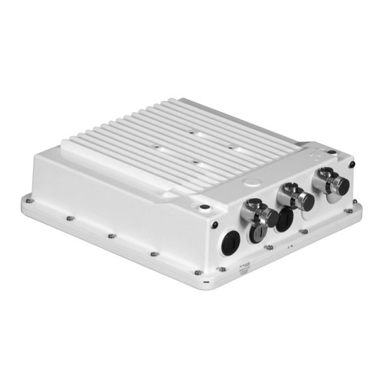
Preface Documentation Conventions Icon Representation Name Image Meaning Note A special instruction that draws attention of a user. Important A note of significant importance that the user should be aware of. Caution A warning that cautions the user of a possible danger. ®... - Page 9 Introduction This chapter contains information on the following: ® 1.1 About Tsunami 800 and 8000 Series Products Product Description Image MP-820-BSU-100 The MP-820 Base Station unit, is a flexible wireless outdoor product that operates in 5.150 – 5.925 GHz frequency band. This connectorized device comes with 2x2 MIMO radio and two N-Type connectors to connect external antennas.
- Page 10 Introduction MP-825-CPE-50 The MP-825 Customer Premises Equipment comes with a 2x2 MIMO radio and 15 dBi integrated dual-polarized panel antenna that operates in 5.15 - 5.925 GHz frequency band with aggregate throughput of 50 Mbps. MP-825-CPE-100 The MP-825 Customer Premises Equipment comes with a 2x2 MIMO radio and 15 dBi integrated dual-polarized panel antenna that operates in 5.150 - 5.925 GHz frequency band with aggregate throughput of 100 Mbps.
- Page 11 Introduction MP-8160-CPE-A100 The MP-8160 Customer Premises Equipment comes with a single high power 2x2 MIMO radio and 15 dBi integrated dual-polarized panel antenna that operates in 5.900 – 6.425 GHz frequency band. MP-826-CPE-50 The MP-826 Customer Premises Equipment comes with a 2x2 MIMO radio, and 15 dBi integrated dual-polarized panel antenna that operates in –...
- Page 12 Introduction QB-8151-LNK A pair of QB-8151-EPR devices form a link. QB-8200-EPA The QB-8200-EPA QuickBridge operates in 4.900 – 5.925 GHz frequency band. This connectorized device comes with a 3x3 MIMO high power radio and three N-Type connectors to connect external antennas.
- Page 13 The underlying technology of Proxim’s product radios are based on a combination of MIMO and OFDM (Orthogonal Frequency Division Multiplexing). MIMO-OFDM combination radios solve interference, fading and multi-path problems. On the receiver side, having multiple receivers increases the amount of received power and also reduces multi-path problems by combining the received signals for each frequency component separately.
-
Page 14: Hardware Overview
800 Series - Hardware Overview and Installation ® This chapter provides hardware overview, and step-by-step procedure to install and mount the following Tsunami series products. 2.1 MP-820-BSU-100 / MP-820-SUA-50 / MP-820-SUA-100/ MP-825-SUR-50 / MP-825-BS3-100 / QB-825-EPR/LNK-50 This section provides the hardware overview and installation procedure for the following products: MP-820-BSU-100 MP-820-SUA-50 MP-825-SUR-50... - Page 15 800 Series - Hardware Overview and Installation Figure 2-2 MP-825-SUR-50 / MP-825-BS3-100/ QB-825-EPR-50 A detailed description about the various components of the device are explained in the following sections. 2.1.1.1 Gigabit Ethernet Port The device comes with one auto-sensing 10/100/1000 BASE-T Ethernet port with configurable Tx modes and speeds. The Gigabit Ethernet port (PoE IN and Data) of the device allows the user to connect to the LAN by using Cat5e/Cat6 Ethernet cable, and also power ON the device by using the Power over Ethernet (PoE) Injector supplied with the product package.
- Page 16 800 Series - Hardware Overview and Installation Figure 2-3 Serial Components Product can be powered either by using 12V supply or through RJ11(Serial port) interface. Pin 6 of RJ11 is used to supply 12V DC to the device. – Product shall be supplied with 12V (+/-10%)/2A DC supply when Serial port power option is used. –...
-
Page 17: Product Package
800 Series - Hardware Overview and Installation 2.1.1.4 Grounding Point To protect the device against lighting or ESD events, you must ground the device properly. To ensure proper grounding, use either of the ground points that are situated at the bottom corner of the device and the grounding screw (M4 thread size) provided to attach a ground wire of at least 12 AWG stranded to the device. - Page 18 800 Series - Hardware Overview and Installation What’s in the Kit Image Mounting Kit and Hardware The mounting kit includes the following: Mounting clamp for wall/pole Extension arm Mounting plate to enclosure Mounting clamp for pole mounting The following table lists and describes some of the items included with the mounting kit: Quantity Description...
-
Page 19: Installation Procedure
Required RSL and fade margin to achieve link availability objectives. For more details on how to calculate RSL and fade margin, please refer to the ‘Antenna Installation Guide’ and ‘Proxim Link Calculator’ that are available on the support site at... -
Page 20: Step 3: Gather Required Tools
Please make a note of the Ethernet addresses, the MAC addresses and the serial number. These addresses may be used when configuring the device. Note that the serial number helps you to seek support from the Proxim’s Customer support team. -
Page 21: Step 6: Assemble Mounting Hardware
800 Series - Hardware Overview and Installation Step 6: Assemble Mounting Hardware 1. Fix the mounting plate (A) by using the provided screws and washers (Torque 9 N . m/75 in-lbs). Mounting Plate Mounting Plate fixed to the device 2. Fix the extension arm (B) to the fixed mounting plate with the provided screw, nut and washers. The extension arm gives the device more possible tilt, letting you adjust for azimuth or elevation over a larger angle. -
Page 22: Step 7: Mount The Device
800 Series - Hardware Overview and Installation 4. Tighten the assembled parts (Torque 15 N . m/130 in-lbs). The following figure shows the full assembled mounting hardware fixed to the device. Figure 2-5 Assembled Device Step 7: Mount the Device 1. -
Page 23: Step 8: Plug In The Cables
800 Series - Hardware Overview and Installation 2. To wall-mount the device, mount the bracket (C) to a wall using 4 screws (not provided), as shown: Figure 2-7 Wall Mounting Step 8: Plug in the Cables : Unscrew the sealing cap for installation of the cable. 1. -
Page 24: Step 9: Connect The Antenna
Ensure to use antenna ports A1 and A2 for dual polarization antennas Step 10: Install Surge Protector Proxim recommends two approved lightning surge protectors to be installed, one near to the device and the other at the building ingress point. -
Page 25: Step 11: Ground The Unit
800 Series - Hardware Overview and Installation Figure 2-10 Surge Protector : Use Outdoor-rated, UV protected, shielded Cat5e/Cat6 cable for the following: 3. Connect an RJ45 terminated cable between the indoor device and to the port on the surge protector at the building ingress. -
Page 26: Step 12: Power On The Device
800 Series - Hardware Overview and Installation Connect the grounding wire, which is supplied with the product package, to the device as shown below: Figure 2-11 Ground the device Step 12: Power ON the Device Plug in the power cord into a power outlet after having connected the PoE Injector and the device using Cat5e/Cat6 cable. There is no ON/OFF switch on the device. -
Page 27: Step 14: Align The Antenna
800 Series - Hardware Overview and Installation Figure 2-12 View LEDs The following table describes the status of LEDs: LED State Ethernet Interface Power/Ethernet LED Wireless LED No Power Radio is not present or failed to detect Amber No Application Image detected (ScanTool Power is ON and device detects reload mode) signal... -
Page 28: Hardware Overview
800 Series - Hardware Overview and Installation 2.2 MP-825-CPE-100/ MP-825-CPE-50 / QB-825-EPR&LNK-50 This section provides the hardware overview and installation method for MP-825-CPE-100, MP-825-CPE-50 and QB-825-EPR-50. 2.2.1 Hardware Overview Figure 2-13 MP-825-CPE-100/ MP-825-CPE-50 / QB-825-EPR-50 The device contains the following features: Features Description Ethernet Port (100 Mbps) - Page 29 800 Series - Hardware Overview and Installation 2.2.1.2 Grounding Point To protect the device against lightning or ESD events, you must ground the device properly. To ensure proper grounding, use the grounding point situated at the bottom corner of the device and the grounding screw (M4 thread size) provided to attach a ground wire of atleast 12 AWG stranded to the device.
- Page 30 Pre-testing equipment (back-to-back test procedure) Step 2: Choose a Location To make optimal use of the device, you must find a suitable location to install the hardware. Proxim recommends you do a site survey, observing the following requirements, before mounting the hardware.
- Page 31 Please make a note of the Ethernet addresses, the MAC addresses and the serial number. These addresses may be used when configuring the device. Note that the serial number helps you to seek support from the Proxim’s Customer support team.
- Page 32 To add an additional layer of protection to the connectors against the environment, see Step 8: Install Surge Protector Proxim recommends two approved lightning surge protectors to be installed, one near to the device and the other at the building ingress point.
-
Page 33: Step 9: Ground The Device
800 Series - Hardware Overview and Installation Perform the following steps to ensure proper surge protection: 1. Mount the surge protector near the outdoor device and use 10 AWG or larger wire to connect the protector’s ground lug to the appropriate mounting ground point. The outdoor device and co-located surge protector should have a common grounding point using the shortest possible grounding cable. - Page 34 800 Series - Hardware Overview and Installation 6. Never install during a storm and always follow your local safety codes. Connect the grounding wire, which is supplied with the product package, to the grounding lug as shown below: Figure 2-18 Ground the Device Step 10: Power ON the Device Plug in the power cord into a power outlet after having connected the PoE Injector and the device using Cat5/5e or better cable.
- Page 35 800 Series - Hardware Overview and Installation Figure 2-19 LED Indicators The following table describes the status of LED: LED State Ethernet Interface Power/Ethernet LED Wireless LED No Power Radio is not present or failed to detect Amber No Application Image detected (ScanTool Power is ON and device detects Reload signal mode) Blinking Green...
- Page 36 800 Series - Hardware Overview and Installation 2.3 MP-826-CPE-50 This section provides the hardware overview and installation procedure for the MP-826-CPE-50 2.3.1 Hardware Overview Figure 2-20 MP-826-CPE-50 The device contains the following features: Features Description Ethernet Port (100 Mbps) PoE IN and data RSSI (Received Signal Strength Indicator) Scaling mask LEDs indicating signal strength Grounding Point...
- Page 37 800 Series - Hardware Overview and Installation : You should use a straight through Ethernet cable between the PoE and the device. When you use a 4-pair cross over Ethernet cable, the reload functionality gets activated and forcibly deletes the operating image. 2.3.1.2 Grounding Point To protect the device against lightning or ESD events, you must ground the device properly.
- Page 38 Pre-testing equipment (back-to-back test procedure) Step 2: Choose a Location To make optimal use of the device, you must find a suitable location to install the hardware. Proxim recommends you do a site survey, observing the following requirements, before mounting the hardware.
- Page 39 Please make a note of the Ethernet addresses, the MAC addresses and the serial number. These addresses may be used when configuring the device. Note that the serial number helps you to seek support from the Proxim’s Customer support team.
- Page 40 800 Series - Hardware Overview and Installation d. Slide the tube-shaped Compression Washer (C) into the Compression Ring (D) and onto the cable from the bare end, and insert into the fixed Connector Body. e. Slide the Sealing Nut (E) over the bare end of the cable and fasten it on the fixed Connector Body. Crimp the bare end of the cable with RJ45 connector and connect it to the LAN+DC port on the PoE Injector.
- Page 41 800 Series - Hardware Overview and Installation Step 8: Install Surge Protector Proxim recommends two approved lightning surge protectors to be installed, one near to the device and the other at the building ingress point. : To buy a suitable Surge Protector, place an order separately with your distributor.
- Page 42 800 Series - Hardware Overview and Installation Step 9: Ground the Device To ensure proper grounding, use the grounding point situated at the bottom corner of the device and the grounding screw provided to attach a ground wire of atleast 12 AWG stranded to the device. It is important that the following grounding guidelines are followed to protect the device against lightning or ESD events: 1.
- Page 43 800 Series - Hardware Overview and Installation Step 11: View LEDs When the device is powered on, it performs startup diagnostics. When startup is complete, the LEDs show the device’s operational status. The LEDs are available at the device’s Ethernet connector inside the enclosure. You can see the LED through the Ethernet connector.
- Page 44 8000 Series - Hardware Overview and Installation ® This chapter provides hardware overview, and step-by-step procedure to install and mount the following Tsunami 8000 series products. 3.1 MP-8100-BSU&SUA / MP-8150-SUR / QB-8100-EPA&LNK / QB-8150- EPR&LNK / QB-8151-EPR&LNK This section provides the hardware overview and installation procedure for the following product(s): MP-8100-BSU MP-8100-SUA MP-8150-SUR...
- Page 45 8000 Series - Hardware Overview and Installation Figure 3-2 MP-8150-SUR / QB-8150-EPR / QB-8151-EPR A detailed description about the various components of the device are explained in the following sections. 3.1.1.1 Gigabit Ethernet Ports The device comes with two auto-sensing 10/100/1000 BASE-T Ethernet ports with configurable Tx modes and speeds. 3.1.1.1.1 a) Ethernet Port 1 The Gigabit Ethernet port 1 (PoE IN and Data) of the device allows the user to connect to the LAN by using Cat5e/Cat6 Ethernet cable, and also power ON the device by using the Power over Ethernet (PoE) Injector supplied with the product...
- Page 46 If power from the second Ethernet Port is desired, then Proxim recommends you to use 60W PoE (not supplied). If a device is connected to the second Ethernet port for data only, then use a PoE Splitter (not supplied).
- Page 47 8000 Series - Hardware Overview and Installation 3.1.1.3 Antenna Ports : Applicable only to MP-8100-BSU, MP-8100-SUA and QB-8100-EPA/LNK. The Antenna Ports A1, A2 and A3 are used to connect external antenna (s). These antenna connectors are of N-Type female with built-in surge protection. : Use antenna port A1 for single polarization antennas, and antenna ports A1 and A3 for dual polarization antennas.
- Page 48 8000 Series - Hardware Overview and Installation What’s in the Kit Image PoE Surge Arrestor Grounding Kit Quick Installation Guide Mounting Kit and Hardware The mounting kit includes the following: Mounting clamp for wall/pole Extension arm Mounting plate to enclosure Mounting clamp for pole mounting The following table lists the items included with the mounting kit: Quantity...
- Page 49 Required RSL and fade margin to achieve link availability objectives. For more details on how to calculate RSL and fade margin, please refer to the ‘Antenna Installation Guide’ and ‘Proxim Link Calculator’ that are available on the support site at...
- Page 50 2. Please make a note of the Ethernet addresses, the MAC addresses and the serial number. These addresses may be used when configuring the device. Note that the serial number helps you to seek support from the Proxim’s Customer support team.
-
Page 51: Step 6: Assemble Mounting Hardware
8000 Series - Hardware Overview and Installation Additional Weatherproofing Steps To add an additional layer of protection to the connectors against the environment, see For detailed explanation to weatherproof RF connections, refer to Antenna Installation Guide, which is available at Step 6: Assemble Mounting Hardware 1. -
Page 52: Step 7: Mount The Device
8000 Series - Hardware Overview and Installation The following figure shows the fully assembled mounting hardware fixed to the device. Figure 3-5 Assembled Device Step 7: Mount the Device 1. To pole-mount the device, insert the provided screws and washers through bracket (F). Fasten around the pole to bracket (C) and secure (Torque 11 N.m/100 in-lbs). -
Page 53: Step 9: Connect The Antenna
48 VDC (15 W average) is present on the second Ethernet port. Make sure the connected device can support this voltage. If power from the second Ethernet Port is desired, then Proxim recommends to use 60W PoE (not supplied). If the device is connected to the second Ethernet port for data, then use a PoE Splitter (not supplied) 3. -
Page 54: Step 11: Ground The Unit
8000 Series - Hardware Overview and Installation Step 10: Install Surge Protector Proxim recommends two approved lightning surge protectors to be installed, one near to the device and the other at the building ingress point. : For an additional Surge Protector, place an order separately with your distributor. -
Page 55: Step 12: Power On The Device
8000 Series - Hardware Overview and Installation important that the following ground guidelines are followed during installations to protect the device against lighting or ESD events: 1. Connect one end of the grounding cable to the device and the other end to the closest earthing system point at the installation. - Page 56 8000 Series - Hardware Overview and Installation LED State Ethernet 1 Power/Ethernet LED Wireless LED No Power Radio is not present or failed to detect Blinking Green-Fast Power is ON and the Ethernet link on Radio is ON and wireless link has not Ethernet 1 is down been established yet Blinking Green...
- Page 57 8000 Series - Hardware Overview and Installation antenna, SNR averaging settles at the new value and the beeping returns to the average length so the antenna can again be aimed for rising SNR. Aiming is complete if moving in any direction results in a falling SNR value (which can be heard as longer periods between beeps).
-
Page 58: Hardware Overview
8000 Series - Hardware Overview and Installation 3.2 MP-8160-BSU / MP-8160-SUA / MP-8160-BS9 This section provides the hardware overview and installation procedure for the following products: MP-8160-BSU MP-8160-BS9 MP-8160-SUA 3.2.1 Hardware Overview Figure 3-14 MP-8160-BSU / MP-8160-SUA Figure 3-15 MP-8160-BS9 A detailed description about the various components of the device are explained in the following sections. - Page 59 If power from the second Ethernet Port is desired, then Proxim recommends you to use 60W PoE (not supplied). If a device is connected to the second Ethernet port for data only, then use a PoE Splitter (not supplied).
- Page 60 8000 Series - Hardware Overview and Installation Figure 3-16 Serial Components The pin assignments for DB9 connector are as follows: D-Shell RJ11 1 + 3 + 5 : The pin6 on RJ11 connector is used as input for 12V DC IN for diagnostic purpose. Supplying power on this pin, when the device is powered by POE injector, might damage the device.
-
Page 61: Product Package
8000 Series - Hardware Overview and Installation 3.2.2 Product Package Each shipment includes the items listed in the following table. Please verify that you have received all the parts in this shipment, prior to installation. What’s in the Kit Image MP-8160-BSU/ MP-8160-SUA/ MP-8160-BS9... -
Page 62: Installation Procedure
8000 Series - Hardware Overview and Installation What’s in the Kit Image Mounting Kit and Hardware The mounting kit includes the following: Mounting clamp for wall/pole Extension arm Mounting plate to enclosure Mounting clamp for pole mounting The following table lists and describes some of the items included with the mounting kit: Quantity Description... -
Page 63: Step 1: Plan For Installation
Required RSL and fade margin to achieve link availability objectives. For more details on how to calculate RSL and fade margin, please refer to the ‘Antenna Installation Guide’ and ‘Proxim Link Calculator’ that are available on the support site at... - Page 64 Please make a note of the Ethernet addresses, the MAC addresses and the serial number. These addresses may be used when configuring the device. Note that the serial number helps you to seek support from the Proxim’s Customer support team.
- Page 65 8000 Series - Hardware Overview and Installation Extension Arm Extension Arm fixed to Mounting Plate fixed to the Mounting Plate device 3. Fix the mounting bracket (C) to fixed extension arm with the provided screw, nut and washers. Extension Arm fixed to Mounting Bracket fixed to Mounting Bracket Mounting Plate...
-
Page 66: Step 7: Mount The Device
48 VDC (15 W average) is present on the second Ethernet port. Make sure the connected device can support this voltage. If power from the second Ethernet Port is desired, then Proxim recommends to use 60W PoE (not supplied). If the device is connected to the second Ethernet port for data, then use a PoE Splitter (not supplied). - Page 67 Step 10: Install Surge Protector Proxim recommends two approved lightning surge protectors to be installed, one near to the device and the other at the building ingress point. : For an additional Surge Protector, place an order separately with your distributor.
- Page 68 8000 Series - Hardware Overview and Installation Figure 3-23 Surge Protector : Use Outdoor-rated, UV protected, shielded Cat5e/Cat6 cable for the following: 3. Connect an RJ45 terminated cable between the indoor device and to the port on the surge protector at the building ingress.
-
Page 69: Step 12: Power On The Device
8000 Series - Hardware Overview and Installation Connect the grounding wire, which is supplied with the product package, to the device as shown below: Figure 3-24 Ground the device Step 12: Power ON the Device Plug in the power cord into a power outlet after having connected the PoE Injector and the device using Cat5e/Cat6 cable. There is no ON/OFF switch on the device. - Page 70 8000 Series - Hardware Overview and Installation Blinking Green-Fast Power is ON and the Ethernet link on Not Applicable Ethernet 2 is DOWN Blinking Green Bootloader detected no image Not Applicable (5 times) and turns off Green Power is ON and the Ethernet link on Not Applicable Ethernet 2 is UP Step 14: Align the Antenna...
- Page 71 8000 Series - Hardware Overview and Installation Antenna Alignment Commands To enable the antenna alignment display from the CLI prompt, enter the following commands: : Enables display of the local signal, noise and SNR. : Enables display of the remote signal, noise and SNR. : Enables display of local and remote signal, noise and SNR.
- Page 72 8000 Series - Hardware Overview and Installation 3.3 MP-8150-CPE / QB-8150-LNK-12/50 This section provides the hardware overview and installation method for the following products: MP-8150-CPE QB-8150-LNK-12/50 3.3.1 Hardware Overview Figure 3-27 MP-8150-CPE / QB-8150-EPR-12 / QB-8150-EPR-50 A detailed description about the various components of the device are explained in the following sections. 3.3.1.1 Ethernet Port (PoE IN and Data) The device comes with auto-sensing 10/100 BASE-T Ethernet port with configurable Tx modes and speeds.
- Page 73 8000 Series - Hardware Overview and Installation The serial connection is established with an RJ11 to DB9 connector (also referred to as a “dongle”) by connecting the RJ11 end of the dongle connector to the device and the other end to your Personal Computer. Figure 3-28 Serial Components The pin assignments for DB9 connector are as follows: D-Shell...
- Page 74 8000 Series - Hardware Overview and Installation 3.3.2 Product Package Each shipment includes the items listed in the following table. Please verify that you have received all the parts in this shipment, prior to installation. What’s in the Kit Image MP-8150-CPE/ QB-8150-EPR-12/ QB-8150-EPR-50...
- Page 75 Pre-testing equipment (back-to-back test procedure) Step 2: Choose a Location To make optimal use of the device, you must find a suitable location to install the hardware. Proxim recommends you do a site survey, observing the following requirements, before mounting the hardware.
-
Page 76: Step 5: Assemble The Cable
Please make a note of the Ethernet addresses, the MAC addresses and the serial number. These addresses may be used when configuring the device. Note that the serial number helps you to seek support from the Proxim’s Customer support team. - Page 77 : Do not over tighten the screws at this stage, as the device may need adjustment to obtain good signal strength. Proxim also provides an optional universal wall mounting kit bracket (P/N 1087-UMK); this kit is designed to mount the device directly to a flat surface such as a roof, wall, or under an eave.
- Page 78 RJ45 LAN port on the PoE Injector. Step 8: Install Surge Protector Proxim recommends two approved lightning surge protectors to be installed, one near to the device and the other at the building ingress point. : To buy a suitable Surge Protector, place an order separately with your distributor.
- Page 79 8000 Series - Hardware Overview and Installation Figure 3-31 Surge Protector : Use Outdoor-rated, UV protected, shielded Cat5/Cat5e or better cable for the following: 3. Connect an RJ45 terminated cable between the indoor device and to the port on the surge protector at the building ingress.
- Page 80 8000 Series - Hardware Overview and Installation Figure 3-32 Grounding the Device Step 10: Power ON the Device Plug in the power cord into a power outlet after connecting the PoE Injector to the device by using Cat5/Cat5e or better cable.
Need help?
Do you have a question about the Tsunami Multipoint MP-820-BSU-100 and is the answer not in the manual?
Questions and answers