
Related Manuals for Triplett CamView IP Pro


Summary of Contents for Triplett CamView IP Pro
- Page 1 IP P IP P & IP P IP P IP P USER MANUAL 99 Washington Street Melrose, MA 02176 Phone 781-665-1400 Toll Free 1-800-517-8431 P/N UM-8071 Rev. 6/2016 Visit us at www.TestEquipmentDepot.com...
-
Page 2: Safety Information
• Do not use the product in an environment containing flammable gases • Do not attempt to disassemble the product. There are no user serviceable parts inside and product damage can occur. Contact Triplett customer service if the unit does not function properly. -
Page 3: Table Of Contents
TABLE OF CONTENTS 1. Introduction............01 1.1 General Use . - Page 4 4.3.5 Testing Remote Analog Monitors and Optical Transmitters/Receivers ..24 4.4 RJ45 Ethernet Cable TDR Test........25 4.4.1 Overview .
-
Page 5: Introduction
1. INTRODUCTION 1.1 General Use The CamView IP Pro, Pro-C, and Pro+ are designed to facilitate the installation and maintenance of surveillance video equipment. They can be used with Standard Definition analog NTSC/PAL camera systems and High Definition ONVIF conformant IP (Ethernet) camera systems. They provide an RS485 port for PTZ control of analog PTZ cameras, and can provide POE power for operating IP cameras, or 12VDC (not to exceed 2A) to power analog cameras. - Page 6 CamView IP Pro, Pro-C, and Pro+ User Manual 1.2.2 Standard Definition Analog Camera Test The Tester can display the analog video signal input from an attached analog camera or video source with NTSC or PAL format video output. The Tester can provide 12VDC (not to exceed 2.0 Amperes) to power the camera.
-
Page 7: Accessories
The Tester may be used to check the condition of the RJ45 cable pairs (normal, open, short) and perform a cable length measurement test using TDR. 1.2.8 High Definition Analog Camera Test (CamView IP Pro-C and Pro+ Only) The Tester will display the analog video signal input from an attached analog camera or video source with AHD or TVI format video output (CamView Pro+ only) or HD-CVI (CamView Pro-C only). -
Page 8: Device Diagram And Functions
CamView IP Pro, Pro-C, and Pro+ User Manual 2. DEVICE DIAGRAMS AND FUNCTIONS 2.1 Front of Tester... - Page 9 CamView IP Pro, Pro-C, and Pro+ User Manual Power Indicator — Lights up when powered on. Title Bar — Displays current function mode and system time. Display Area — Displays various user interface menus. On-Screen Instructions — Displays what your options are in the current screen and how to apply them.
-
Page 10: Keyboard Features
CamView IP Pro, Pro-C, and Pro+ User Manual 2.2 Front of Tester (Keyboard) 17 18 19 2.3 Back of Tester 2.4 Top of Tester... - Page 11 CamView IP Pro, Pro-C, and Pro+ User Manual TAB Key — Press to switch between input fields on the screen (e.g., username to pwd) CAPS Key — Select to turn Caps Lock on/off SYMBOL Key — Select to switch between letters and symbols on the keyboard ENTER Key —...
-
Page 12: Right Side Of Tester
CamView IP Pro, Pro-C, and Pro+ User Manual 2.5 Right Side of Tester 2.6 Left Side of Tester... - Page 13 CamView IP Pro, Pro-C, and Pro+ User Manual Power Button • Press and hold for 2 seconds to turn the tester on / off • Press twice quickly to turn the Flashlight on / off (Flashlight feature may be used while the tester is on) Audio Input Jack —...
-
Page 14: Basic Operation
3.3 Frequently Asked Questions About the Battery • The CamView IP Pro, Pro-C, and Pro+ use a lithium-ion polymer battery, which does not have a memory effect. Users can recharge the battery whenever they want. -
Page 15: Lanyard
• The battery can also be charged using a POE switch or other POE power sources that meet the 802.3af / 802.3at standard. However, we strongly recommend using the original POE injector provided with your CamView IP Pro, Pro-C, or Pro+ unit. DO NOT USE A NON-STANDARD POE POWER SUPPLY TO CHARGE THE BATTERY—THIS CAN DESTROY THE TESTER. -
Page 16: How To Use Your Camview Pro, Pro-C, And Pro
4. HOW TO USE YOUR CAMVIEW IP PRO, PRO-C, OR PRO+ 4.1 Main Menu When the CamView IP Pro-C/Pro+ first boots up, you will see the following Main Screen. (NOTE—CamView IP Pro Testers will show fewer options.) You can navigate this screen using the Up or Down Arrow Keys. Once you have highlighted the function you want to use, press the Right Arrow Key to go to the Interface Screen for that feature. - Page 17 CamView IP Pro, Pro-C, and Pro+ User Manual OPTION 2 For non-POE IP cameras, the camera can either be powered using its own 12V power adapter or using the Tester’s 12V/2A power output. When using the Tester’s 12V/2A output, please use the 12V power cable supplied to connect the Tester’s 12V Output Port to the camera’s 12V power...
-
Page 18: Using The Interface - Step-By-Step Instructions
IP Camera testing: STEP 1: Power Up the Tester Press the Power Button on the side of your CamView IP Pro, Pro-C, or Pro+ Tester to turn it on if it is not already powered on. - Page 19 CamView IP Pro, Pro-C, and Pro+ User Manual For example, if the camera’s IP address is 10.1.1.100, you would enter that into the “URL” field and then press the TAB Key. The Tester should then automatically append the IP address to include “.../onvif/device_service” at the end of the original 10.1.1.100 address.
-
Page 20: Diagram And Details Of Ovif Interface Screen
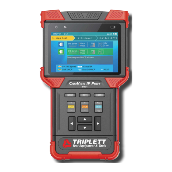
CamView IP Pro, Pro-C, and Pro+ User Manual 43 44 Network Port 1 Status Information — Also referred to as the Blue Bar, all of the information for the camera connected to Port 1 (blue RJ45 port on the side of the Tester) will show in this row. - Page 21 CamView IP Pro, Pro-C, and Pro+ User Manual Link Speed of Corresponding Port — The Link Speed displays above the bar icon. shows for each Port. The link speed can also be observed via the icon itself. • If the bar icon is gray, there is no network connection. It will also say “Link Down”...
- Page 22 CamView IP Pro, Pro-C, and Pro+ User Manual CAMERA SETTINGS: While you are in the Discover screen, you can press the SET Key to enter the Camera’s Settings Screen. The left side of the display shows the Setting’s Class, and the right side shows the details of the camera’s setting within that class.
- Page 23 CamView IP Pro, Pro-C, and Pro+ User Manual You may also export a report about this camera by selecting the SCR Key. You can retrieve the report, along with any screenshots or recordings, by plugging the mini USB cable into the tester and then attaching it to your computer.
-
Page 24: Testing Analog Cameras
CamView IP Pro, Pro-C, and Pro+ User Manual 4.3 Testing Analog Cameras 4.3.1 Overview You can test standard Analog (NTSC/PAL) cameras with the Pro model, NTSC/PAL & HD-CVI with the Pro-C model, or you can test NTSC/PAL, AHD & HD-TVI cameras if you have the Pro+ model. - Page 25 Analog Camera testing: STEP 1: Power Up the Tester Press the Power Button on the side of your CamView IP Pro, Pro-C, or Pro+ Tester to turn it on if it is not already powered on.
-
Page 26: Using The Interface - Step-By-Step Instructions
CamView IP Pro, Pro-C, and Pro+ User Manual To access and change the Tester’s settings to match the camera’s settings, press SET and then use the Arrow Keys to navigate the screen. (See image above.) When adjusting the parameters, press Iris- to restore previous values if you don’t want to save the setting. -
Page 27: Analog Video Generator
CamView IP Pro, Pro-C, and Pro+ User Manual 4.3.4 Analog Video Generator On the Main Menu, highlight “Analog Video Generator” (press the MODE button to enter the Main Menu if you are not already on it; press the Up or Down Arrow Keys to highlight it). Once the “Analog Video Generator”... -
Page 28: Testing Remote Analog Monitors And Optical Transmitters/Receivers
CamView IP Pro, Pro-C, and Pro+ User Manual 4.3.5 Testing Remote Analog Monitors and Optical Transmitters/Receivers You can transmit generated video to the remote monitor or DVR using the BNC Out jack (see im- age below). This will allow you to test the cable and monitor by comparing the image quality on the Tester to the image quality on the monitor. -
Page 29: Rj45 Ethernet Cable Tdr Test
STEP 1: Power Up the Tester Press the Power Button on the side of your CamView IP Pro-C or Pro+ Tester to turn it on if it is not already powered on. STEP 2: Connect the Ethernet Cable to the Tester... - Page 30 CamView IP Pro, Pro-C, and Pro+ User Manual 50 51 52 53 Network Port 1 Icon Tape Measure — Flashes just under the Network Port icon when a cable is being tested. Network Port 2 icon Cable Pairs — Both by number and color pattern.
-
Page 31: Testing For Breaks In Ethernet Cable Using Tdr
STEP 1: Power Up the Tester Press the Power Button on the side of your CamView IP Pro-C or Pro+ Tester to turn it on if it is not already powered on. - Page 32 CamView IP Pro, Pro-C, and Pro+ User Manual cable. The second example below shows the results from a cable with an open on the green pairs and the length to that open from each end of the cable. NOTE — Do not use the Repeat Test feature when performing this test as the test results will be...
-
Page 33: Network Analysis Tools
CamView IP Pro, Pro-C, and Pro+ User Manual 4.5 Network Analysis Tools 4.5.1 Overview Network analysis is a combination of several network tools, including Ethernet Sniff, Subnet List, and Ping test. 4.5.2 Network Tools Test Screen and Operation On the Main Menu, highlight “Network Tools” (press the MODE button to enter the Main Menu if you are not already on it;... - Page 34 CamView IP Pro, Pro-C, and Pro+ User Manual Tester’s Current Network Settings • IP/Mask - Tester’s IP Address and Subnet Mask. Select SET to change. • GW/DNS - Tester’s Gateway and DNS. Select SET to change. • Destination - Ping destination. When the bar is yellow, use the Flip Keyboard to change the information in this field.
- Page 35 CamView IP Pro, Pro-C, and Pro+ User Manual LIST SUBNET: To use the List Subnet function, IP and Mask should be set up, and the Subnet Mask should be 24bits wide (subnet size of 256 devices, or 8 bits). Refer to the instructions on page 29 if you need to update the IP, Subnet Mask, or Gateway.
-
Page 36: Recording, Reviewing, And Accessing Snapshots And Videos
CamView IP Pro, Pro-C, and Pro+ User Manual Ping 10.1.1.1 Average: 3ms **************** 10ms 30ms 0.1s 0.3s Lost 4.6 Recording, Reviewing, and Accessing Snapshots and Videos 4.6.1 Overview The Tester can take snapshots of or record input from video, then save the files to internal storage as either .jpg or .avi files. -
Page 37: Device Settings And Updating The Firmware
CamView IP Pro, Pro-C, and Pro+ User Manual 4.7 Device Settings and Updating the Firmware 4.7.1 Overview There are many other features in the Tester that you can adjust or view, including the screen’s language, Auto Shutoff delay, Serial Number, and so forth. There may also be times when you need to update the firmware or export files to a computer. -
Page 38: Upgrading Firmware And Identifying Current Firmware Version
Tester up-to-date with the most recent firmware. Follow these steps to update the firmware: STEP 1: Power Up the Tester Press the Power Button on the side of your CamView IP Pro, Pro-C, or Pro+ Tester to turn it on if it is not already powered on. - Page 39 CamView IP Pro, Pro-C, and Pro+ User Manual STEP 5: Run the Firmware Upgrade If you have internet access, the Tester will automatically check for new firmware updates when you initially land on the Check Upgrade screen. If, however, you see an error that states “Network Failed”...
-
Page 40: Exporting Reports
STEP 1: Power Up the Tester Press the Power Button on the side of your CamView IP Pro, Pro-C, or Pro+ Tester to turn it on if it is not already powered on. STEP 2: Connect the Tester to the Computer Plug the mini-USB end of the cable into the Tester, and plug the standard USB end of the cable into your computer. -
Page 41: Audio Test
Monitor feature. STEP 1: Power Up the Tester Press the Power Button on the side of your CamView IP Pro, Pro-C, or Pro+ Tester to turn it on if it is not already powered on. STEP 2: Connect the Tester’s RS485 Port to the Camera’s RS485 Hookup You can use the Alligator clips with the RS485 plug to do this. -
Page 43: Appendix 1: Sample Onvif Report
CamView IP Pro, Pro-C, and Pro+ User Manual APPENDIX 1: SAMPLE FIRST PAGE OF ONVIF REPORT NOTE — Data and format are dependent on the specific IP camera. -
Page 44: Appendix 2: Technical Specifications
CamView IP Pro, Pro-C, and Pro+ User Manual APPENDIX 2: TECHNICAL SPECIFICATIONS PORTS Network Ports (2) 10M/100M/1G RJ45 ports (Blue is POE Out; Green is POE In) I/O Ports (2) BNC ports (Video IN and Video OUT), (1) RS485, (1) Audio In, (1) USB, (1) Reset Button... - Page 45 CamView IP Pro, Pro-C, and Pro+ User Manual SYSTEM Screen 4.0 inch TFT 800*RGB*480(WVGA) resolution, 16.7M color, backlight brightness adjust- able Operation Method Power key, 12 control keys, QWERTY flip-open keyboard with 45 keys Auto Power Off Disable / 5~60 minutes...
-
Page 46: Warranty And Technical Support
Triplett / Jewell Instruments extends the following warranty to the original purchaser of these goods for use. Triplett warrants to the original purchaser for use that the products sold by it will be free from defects in workmanship and material for a period of (1) one year from the date of purchase.
Need help?
Do you have a question about the CamView IP Pro and is the answer not in the manual?
Questions and answers
Can you retrieve deleted video you accidentally deleted on the IP pro+8071