Advertisement
Quick Links
User Manual
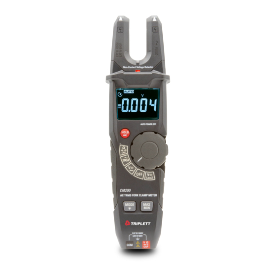
CM200
200A TRMS AC Open Jaw Clamp
Introduction
Congratulations on your purchase of the Triplett CM200 200A True RMS AC
Open Jaw Current Clamp meter. The True RMS AC Open Jaw Clamp meter
features:
Open Jaw Current measurement
Data Hold and Flash Light
Negative Polarity LCD Display
Low Z (Input Impedance) Testing AC/DC Voltage
Non-contact AC voltage detection
Auto Power OFF
Advertisement

Related Manuals for Triplett CM200


Summary of Contents for Triplett CM200
- Page 1 User Manual CM200 200A TRMS AC Open Jaw Clamp Introduction Congratulations on your purchase of the Triplett CM200 200A True RMS AC Open Jaw Current Clamp meter. The True RMS AC Open Jaw Clamp meter features: Open Jaw Current measurement ...
-
Page 2: Safety Notes
Safety International Safety Symbols This symbol, adjacent to another symbol or terminal, indicates the user must refer to the manual for further information. This symbol, adjacent to a terminal, indicates that, under normal use, hazardous voltages may be present Double insulation SAFETY NOTES ... - Page 3 Description Meter Description NCV (Non-Contact Voltage) Sensor Open Jaw Clamp NCV (Non-Contact Voltage) Indicator LED Negative Polarity LCD Display Rotary Switch Indicator LED Rotary Function Switch Rotary Switch Backlight Data HOLD/Flashlight Button MODE/Backlight Button 10. MAX/MIN Button 11. Flashlight 12. Battery Cover 13.
- Page 4 Display Icons Description 1. Alternating Voltage and Current Minus Sign 3. Direct Voltage and Current Auto Power Off (APO) Auto Range Mode Continuity Test Diode Test Low Battery Units of Measure 10. Display Digits 11. MAX/MIN 12. Data Hold 13. Lo Z (Low Impedance Input Mode)
-
Page 5: Operation
Operation AC Current Measurements *NOTE: Ensure that the test leads are disconnected from the meter before making current clamp measurements.* Set the Function switch to the AC Current. Place the current open jaw around the middle of the test lead. The clamp meter LCD will display the reading. - Page 6 Touch the test leads to the circuit under test. Read the voltage on the LCD display. Resistance Measurements Set the function switch to the V Ω CAP position. Insert the black test lead banana plug into the negative COM jack. Insert the red test lead banana plug into the positive jack.
- Page 7 4. Touch the test probe tips across the part under test. 5. Read the capacitance value in the display. 6. The display will indicate the proper decimal point and value. For very large values of capacitance measurement it can take several minutes before the final reading stabilizes.
- Page 8 Function Buttons MODE and Backlight Button • Press MODE and Backlight Button to select OHM/Diode/Continuity/CAP/LoZ AC/DC Voltage. • Press the MODE and Backlight button for over 1 second to turn the button, Knob and Rotary light on. • Press again for over 1second to turn the button, Knob, and Rotary light off. MAX/MIN Button •...
-
Page 9: Maintenance
Maintenance WARNING: To avoid electrical shock, disconnect the meter from any circuit, remove the test leads from the input terminals, and turn OFF the meter before opening the case. Do not operate the meter with an open case. Cleaning and Storage Periodically wipe the case with a damp cloth and mild detergent;... -
Page 10: Specifications
Specifications Function Range Resoluti Accuracy ±(% of reading+digits) AC True RMS 200.0A 100mA ±(3% + 5 digits) Current Over Rang Protection: Maximum input 200A; Frequency Response: 50 to 60Hz AC True RMS 1.000 to 6.000V ±(1.2% + 5 digits) Voltage (Auto Sense) 60.00V 10mV ±(1.2% + 2 digits) - Page 11 Function Range Resolution Accuracy ±(% reading+digits) Capacitance 60.00nF 0.01nF ±(3% + 5 digits) 600.0nF 0.1nF 6.000µF 60.00µF 0.01µF 600.0µF 0.1µF ±(3.5% + 10 digits) 4000µF 1µF ±(5.0% + 10 digits) * >6nF no specification; Over Rang Protection: 300V rms Function Testing Condition Reading Diode...
- Page 12 Triplett / Jewell Instruments extends the following warranty to the original purchaser of these goods for use. Triplett warrants to the original purchaser for use that the products sold by it will be free from defects in workmanship and material for a period of (1) one year from the date of purchase.
- Page 13 Accessories, including batteries are not covered by this warranty Copyright © 2020 Triplett www.triplett.com...
Need help?
Do you have a question about the CM200 and is the answer not in the manual?
Questions and answers