Advertisement
Quick Links
User Manual
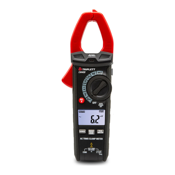
CM400
400A TRMS AC Clamp Meter
Introduction
Congratulations on your purchase of the Triplett CM400 400A True RMS AC
Clamp meter. The CM400 True RMS AC Clamp meter features:
AC Current measurements up to 400A.
Variable Frequency Drive (VFD) Voltage Measurements
Inrush Current Mode
Temperature Measurements
Non-contact AC voltage detection
Auto Power OFF
Advertisement

Subscribe to Our Youtube Channel
Related Manuals for Triplett CM400


Summary of Contents for Triplett CM400
- Page 1 User Manual CM400 400A TRMS AC Clamp Meter Introduction Congratulations on your purchase of the Triplett CM400 400A True RMS AC Clamp meter. The CM400 True RMS AC Clamp meter features: AC Current measurements up to 400A. Variable Frequency Drive (VFD) Voltage Measurements ...
-
Page 2: Safety Notes
Safety International Safety Symbols This symbol, adjacent to another symbol or terminal, indicates the user must refer to the manual for further information. This symbol, adjacent to a terminal, indicates that, under normal use, hazardous voltages may be present Double insulation SAFETY NOTES ... - Page 3 Description Meter Description NCV (Non-Contact Voltage) Sensor Current Clamp NCV (Non-Contact Voltage) Indicator LED Clamp Trigger Rotary Function Switch LCD Display Data HOLD/Flashlight Button REL/Backlight Button Range Button 10. MODE and VFD Button 11. PEAK and INRUSH Button 12. Flashlight 13.
- Page 4 Display Icons Description REL/ ZERO Button 2. Alternating Current/Voltage 3. Direct Current/Voltage 4. Minus Sign 5. Low Battery 6. Auto Range Mode 7. INRUSH Current Mode 8. Display Hold 9. MAX/MIN Mode 10. Variable Frequency Drive (VFD) Voltage Value 11. Diode Test 12.
-
Page 5: Operation
Operation AC Current Measurements *NOTE: Ensure that the test leads are disconnected from the meter before making current clamp measurements.* Set the Function switch to the 400A range. If the approximate range of the measurement is not known, select the highest range then move to lower ranges if necessary. - Page 6 AC Voltage Measurements Insert the black test lead into COM input jack and the red test lead into the Positive input jacks. Set the function switch to the VAC position. Press the MODE/VFD Button for 1 second to turn on the VFD test. Press the INRUSH/PEAK Button to turn on PEAK test.
- Page 7 Capacitance Measurements WARNING: To avoid electric shock, discharge the capacitor under test before measuring. Set the function switch to the ΩCAP position. Insert the black test lead into the COM input jack and the red test lead into the Positive input jacks. Touch the test probe tips across the part under test, If “OL”...
- Page 8 Diode Measurements Insert the black test lead into the COM input jack and the red test lead into the Positive input jacks. Turn the function switch to “ ” position. Use the MODE Button to select the diode function if necessary (Diode symbol will appear on the LCD when in Diode test mode) Touch the test probe tips to the diode or semiconductor junction under test.
- Page 9 Function Buttons MODE and VFD Button • Short Press the MODE/VFD Button to toggle between modes available for the rotary switch position (V/Hz/%) • Long Press and Hold the MODE/VFD while POWERING ON will disable the Auto Power OFF (APO) Function •...
- Page 10 • In AC voltage test mode, Press PEAK/INRUSH Button the Peak maximum and Peak minimum values are measured. • In current test mode, Press PEAK/INRUSH Button the Inrush current values are measured. Relative/Backlight Button The relative measurement feature allows you to make measurements relative to a stored reference value, A reference voltage, current, Capacitance etc.
-
Page 11: Maintenance
Maintenance WARNING: To avoid electrical shock, disconnect the meter from any circuit, remove the test leads from the input terminals, and turn OFF the meter before opening the case. Do not operate the meter with an open case. Cleaning and Storage Periodically wipe the case with a damp cloth and mild detergent;... -
Page 12: Specifications
Specifications Note: Accuracy is given as ±(% of reading + counts of least significant digit) at 23 C /±5 , with relative humidity less than 80%RH. Function Range Resolution Accuracy ±(% of reading+digits) AC True RMS 40.00A 10mA ±2.0% of rdg ± 8 digits Current 400.0A 100mA... - Page 13 Function Range Resolution Accuracy ±(% of reading+digits) Capacitance 99.99nF* 0.01nF ±4.5% of rdg ± 20 digits (Auto-Ranging) 999.9nF 0.1nF 9.999µF 0.001µF 99.99µF 0.01µF ±3.0% of rdg ± 5 digits 999.9µF 0.1µF 9.999mF 0.001mF 99.99mF 0.01mF ±5% of rdg ± 5 digits Input Protection: 300Vdc or 300V ac rms.
- Page 14 General Specifications Clamp Jaw Opening 1.2” (30mm) approx Display 3-3/4 digits (4000 Counts) backlit LCD Low Battery Indication “ ” is displayed Over-Range Indication “OL” display Measurement Rate 3 readings per second, nominal Temperature Sensor Type K thermocouple Input Impedance 10MΩ(VDC and VAC) AC Response True rms (AAC and...
- Page 15 Warranty Information Triplett / Jewell Instruments extends the following warranty to the original purchaser of these goods for use. Triplett warrants to the original purchaser for use that the products sold by it will be free from defects in workmanship and material for a period of (1) one year from the date of purchase.
Need help?
Do you have a question about the CM400 and is the answer not in the manual?
Questions and answers