Table of Contents
Advertisement
Quick Links
Advertisement
Table of Contents

Related Manuals for Triplett CM3000


Summary of Contents for Triplett CM3000
- Page 1 CM3000 1000A TRMS AC/DC Clamp with 3000A AC Flex...
-
Page 2: Safety Instructions
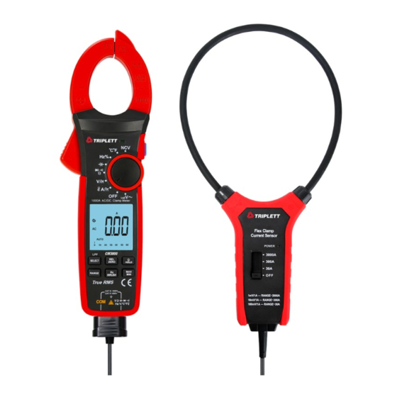
III. Safety Instructions IV. Electrical Symbols The meter is designed and manufactured according to IEC61010-1, IEC61010- 2-032 and IEC61010-2-033 safety standards, and conforms to CAT III 1000V, Symbol Description CAT IV 600V, double insulation, and pollution degree 2. Equipment protected throughout by DOUBLE INSULATION Note: Before each use, verify meter operation by measuring a known voltage. - Page 3 VI. LCD Display V. External Structure (Picture 1) (Picture 2, Picture 3, Picture 4) 9 10 1. Clamp jaws 2. Hand guard 3. LED indicator light 4. Jaw opening trigger Function dial 6. LCD display 7. Function buttons 8. NCV sensor 9.
- Page 4 10 11 12 13 14 15 16 9 10 11 12 21 22 Picture 4 UT206B/UT208B Low battery Continuity test Inrush current measurement 16 17 18 High voltage Low impedance measurement Picture 3 UT207B Auto power off Unit Low battery Continuity test Range indicator for the flexible Relative value...
-
Page 5: Function Dial
2. Function Buttons VII. Function Dial and Function Buttons Note: 1.Function Dial Short press: pressing a button for less than 2s. Description Long press: pressing a button for more than 2s. Dial Position AC/DC current measurement 1) SELECT Button Short press: switch between functions for each dial position. AC/DC voltage measurement 位... -
Page 6: Specifications
6) Hz/INRUSH Button 2. Environmental Specifications Short press: enter/exit the frequency measurement mode. Operating altitude:----------------------------- 2000m Only valid for ACV, LPF ACV, LoZ V~, ACA and measurement by flexible current Safety standards:----------------------------- IEC61010-1, IEC61010-2-032, probe. IEC61010-2-033; Long press: user has the option to select proper range with RANGE button first, CAT III 1000V, CAT IV 600V or simply long press this button to enter the inrush current measurement mode Pollution degree:------------------------------- 2... -
Page 7: Inrush Current
1) AC Current ( 2) Inrush Current ( Overload Overload Range Accuracy Range Accuracy Resolution Function Resolution Protection Protection 60.00A 0.01A ±(2.0%+9) Inrush current 60.00A 0.01A ± (10%+10) 600.0A 0.1A 1000A (ACA) 1000V DC/AC 1000A 600.0A 0.1A ± (2.0%+5) 30.00A 0.01A Inrush current 1000A... - Page 8 a) Add 4% when crest factor is 1~2 4 AC Voltage b) Add 5% when crest factor is 2~2.5 Range Accuracy c) Add 7% when crest factor is 2.5~3 Resolution Overload Protection The -3dB frequency of LPF is about 2.5kHz 6.000V 0.001V Only manual range for LPF ACV.
- Page 9 7) DC voltage ( 9) Continuity ( Range Accuracy Resolution Overload Protection Range Accuracy Resolution Overload Protection 600.0mV 0.1mV Open circuit: Resistance ± (0.8%+3) ≥70Ω, no beep 6.000V 0.001V 600.0Ω 0.1Ω 1000A Well-connected circuit: 60.00V 0.01V 1000A Resistance ≤30Ω, ± (0.5%+5) 600.0V 0.1V consecutive beeps...
- Page 10 Measurement result = displayed value – capacitance of open-circuit test leads 14) Non-contact AC voltage sensing (NCV) For capacitance ≤1μF, it is recommended to use “REL” measurement mode. Range Accuracy Overload Protection Accuracy guarantee: 5%~100% of range Bring the NCV sensor (upper tip) close 12) Temperature (°C/°F) to a wire to start sensing.
- Page 11 AC Current Measurement Note: 1) Turn the function dial to A~, , or position. The current measurement should be taken within 0°C~40°C. Do not suddenly 2) Press the trigger to open clamp jaws and fully enclose one conductor (only release the trigger, as the impact may change the reading for a short time. one conductor can be measured at a time).
- Page 12 3. Measurement by Flexible Current Probe (Picture 6) Inrush Current Measurement 1) After connecting the flexible current probe, short press the RANGE button to select the proper range. 2) Long press the Hz/INRUSH button to enter the inrush current measurement mode.
- Page 13 4. Related Measurement of AC Voltage and Voltage Frequency Measurement LPF ACV (Picture 7) 1) When the function dial is in the AC voltage, short press Hz or Hz/INRUSH button to enter the frequency measurement mode. 2) Short press Hz or Hz/INRUSH button again to exit frequency measurement mode.
- Page 14 5. DC Voltage Measurement (Picture 7) LoZ ACV Frequency Measurement 1) When the function dial is in the LoZ ACV position, short press the Hz/INRUSH 1) Insert the red test lead into the jack, and black test lead button to enter the frequency measurement mode. into the COM jack.
- Page 15 When measuring resistance above 1MΩ, it is normal to take a few seconds to 7. Resistance Measurement (Picture 9) stablize reading. Use caution when working with voltage above AC 30Vrms, 42Vpeak or DC 60V. Those voltages may pose shock hazard. After completing the measurement, disconnect the test leads from the circuit under test.
- Page 16 1) Insert the red test lead into the jack, and black into the 3) Connect the red probe with the diode anode, and black with the diode cathode. COM jack. 4) Read the approximate forward voltage of the diode on the display. For silicon 2) Turn the function dial to the position, short press the SELECT button PN junction, the normal value is generally about 500~800 mV.
- Page 17 1) Turn the function dial to the °C°F position, and the LCD will display “OL”. 1) Insert the red test lead into the jack, and black into the Ambient temperature will be displayed if users short-circuit the test leads. COM jack. 2) Insert the K-type thermocouple into the meter as shown.
-
Page 18: Auto Power Off
X. Maintenance 1) Turn the function dial to the NCV position, and bring the NCV sensor close to Warning: Before opening the rear cover of the meter, remove the test leads the wire under test. to avoid electric shock. 2) If there is AC voltage or electromagnetic field in the space, the LCD will display the sensing intensity from weak to strong by “—”.
Need help?
Do you have a question about the CM3000 and is the answer not in the manual?
Questions and answers