Table of Contents
Advertisement
Quick Links
Advertisement
Table of Contents

Subscribe to Our Youtube Channel
Related Manuals for Triplett CableRater


Summary of Contents for Triplett CableRater
- Page 1 TRIPLETT CableRater dB Loss Meter Instruction Manual 84-875 6/08...
-
Page 2: Table Of Contents
Loss or Gain between the Transmitter and Receiver measured with the press of a button. The CableRater is an invaluable tool for verifying the design of a Cable TV distri- bution system, prior to the connection of any Cable TV services. It can be used to troubleshoot a newly installed distribution system prior to, or following, the application of drywall. -
Page 3: Product Features
2.3) Do not operate the CableRater with any of the product’s covers open or removed. A dangerous potential applied to the F connectors may appear on the battery connector or other parts in the product. -
Page 4: Specifications
5: SPECIFICATIONS 5.1) Transmitter 5.1.1) Output Level ..... Approx 10dBmV +/- 3dB 5.1.2) Output Frequency ....Approx 61.25MHz (Channel 3) 5.1.3) Output Impedance . - Page 5 (whose frequency is the same as the ingress signal). If the CableRater is connected to a distribution system with ingress, the ingress signal might be measured by the CableRater, causing an error in the Loss mea- surement. The distribution system will not operate properly if there is ingress. So, if in- gress is detected by the CableRater this problem must be corrected before per- forming a Loss Test.
-
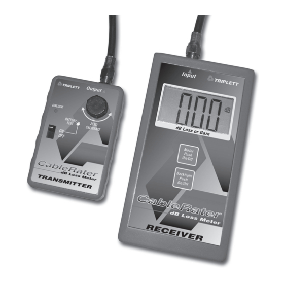
Page 6: Transmitter Front Panel
6: TRANSMITTER FRONT PANEL UNLOCK Figure 1 A) Battery Test LED B) Unlock Button C) ON / OFF Power Switch D) Output Connector E) Zero Calibrate Knob... -
Page 7: Receiver Front Panel
7: RECEIVER FRONT PANEL Figure 2 A) LCD Display with Backlight B) Low Battery Annunciator C) Auto Power Off (APO) Annunciator D) Under Range Annunciator E) Backlight Button F) Power Button G) Input Connector... -
Page 8: Preparing For Use
8: PREPARING FOR USE 8.1) Installing Battery in Transmitter 8.1.1) Remove screw from the back of the Transmitter case. 8.1.2) Carefully remove the front panel of the Transmitter. 8.1.3) Install 9 volt battery. 8.1.4) Reassemble Transmitter. 8.2) Installing Battery in Receiver, Setting Auto Power Off (APO) 8.2.1) Remove 2 screws located on the back, bottom, of the Receiver. -
Page 9: Operation
Note: Be careful not to drop the jumper inside the product when changing the settings. 8.2.4) After setting the jumpers as desired, install battery and replace battery cover. Refer to Figures 1 and 2 for locations of the controls. 9: OPERATION 9.1 Description of Transmitter 9.1.1 ON / OFF Power Switch and UNLOCK Button When the Transmitter is not in use, the ON / OFF switch should be placed in the... - Page 10 9.1.3 ZERO CALIBRATE Knob The ZERO CALIBRATE knob is used to ‘calibrate’ the Transmitter to the Receiver (more on this later). It can be turned clockwise or counterclockwise to increase or decrease the level of the test signal generated by the Transmitter. 9.1.4 OUTPUT Connector The OUTPUT connector is a standard F connector (the kind commonly used for cable TV installations).
- Page 11 If a cable is connected to the Input jack, and the Underrange indication is ob- served when the Receiver is turned On, the cable is not connected to the test signal (from the CableRater Transmitter), or something between the Transmitter and Receiver is introducing so much Loss that the signal is unmeasureable.
- Page 12 9.3.1 Testing for Ingress Ingress, and problems associated with it, are described in section 5.3.2. Before performing any Loss or Gain tests with the CableRater, it is a good idea to test for ingress. An ingress test is performed without cable TV service connected to the cable TV distribution system.
- Page 13 Observe the reading on the CableRater. If any reading is obtained, other than the Underrange indication, ingress is occurring. The higher the reading, the more ingress. This condition must be resolved before testing for Loss. 9.3.2 Fixing Ingress The common cause of ingress is a coaxial cable with an open shield. The cable itself may be OK, but the shield may be losing its connection where the F con- nector screws on to the splitter or other device.
- Page 14 9.4 Calibrating the Transmitter To calibrate the Transmitter, a patch cable is used to connect the Output jack of the Transmitter to the Input jack of the Receiver. See Figure 5. UNLOCK Figure 5 Turn On the Transmitter by holding the UNLOCK button down and moving the ON/OFF switch to the ON position.
- Page 15 ZERO CALIBRATE knob for the duration of the testing. Important Note: The level of the test signal from the CableRater Transmitter can change slightly if the Transmitter temperature changes. Consider this behavior if moving the Trans- mitter from a warm to a cold location, or vice versa.
- Page 16 40 Mega Hertz (MHz) to about 900MHz. The CableRater performs tests at about 60MHz. There are many resources ‘on line’ (on the Internet) that give details on the Loss of various types of cables. Figure 6 shows some typical Loss figures for RG-59 and RG-6. Notice that the Loss at 60MHz for 100ft of RG-59 and RG-6 is about the same (2.4dB vs 2.1dB).
- Page 17 Important Note: Occasionally, the CableRater may indicate that a longer cable has less Loss. This is possible if the longer cable in question is made with premium materials and superior construction techniques. However, if the cable is less than 30ft long, its more likely that the CableRater is “lying”.
- Page 18 Loss should be similar to the Loss shown in Figure 7. Note: The CableRater displays Loss as a negative or ‘minus’ value in dB. So a 2 way splitter would read about ‘-3.5dB’...
- Page 19 The CableRater is limited to testing Gain up to about 40dB. Attempting to mea- sure higher gains will produce inaccurate results. To test the Gain of an amplifier, first calibrate the Transmitter as described in 9.4. Then connect the CableRater Transmitter’s output to the amplifier’s input, and the amplifier’s output to the CableRater Receiver’s input, as shown in Figure 9.
- Page 20 In such a case, the CableRater will measure the Gain as being lower than expected. If saturation is suspected, reduce the input level to the amplifier with an attenuator, then measure the gain of the amplifier with the CableRater, adding the attenuator loss to the Gain displayed on the CableRater to obtain the correct amplifier gain.
- Page 21 (see Figure 7) could be added to supply 6 outlets with a signal of ap- proximately +5dBmV. To test the system for the appropriate Loss, first calibrate the CableRater Transmitter to the Receiver, then connect the Transmitter to the splitter input and measure each outlet for Loss with the Receiver. The Loss should measure about 9 or 10dB.
- Page 22 A ‘star’ or ‘home run’ scheme is often used. A coaxial cable (coax) from each room is run back to a common point, where the splitters and amplifiers are located. This might be a Structured Wiring panel or a board attached to a base- ment wall.
- Page 23 15dB, or 20dB. A 15dB amplifier would be a good choice . This would raise the level at each outlet to about +7 to +9dBmV. To use the CableRater to test this system, first without the amplifier.. connect the Transmitter to the input of the 16 way splitter. Then, connect the Receiver to each outlet and measure the Loss.
- Page 24 When a large number of cables have been installed and are unmarked, the CableRater can aid in identifying the cables. The typical distribution system lay- out has the ends of all of the cables routed to a central location, and the far ends of these cables located in the areas where televisions will be connected.
- Page 25 SLM will undoubtedly be more accurate for measuring the signal level on the cable. However, if an SLM is not available, the CableRater can be used to make a comparison measurement between a location known to have good signal level, and a location in which the signal level is unknown.
-
Page 26: Maintenance
10: MAINTENANCE The CableRater contains no user serviceable parts. To clean the outside of the CableRater, use a cloth dampened with a mild deter- gent solution. Do not use abrasive cleansers or chemical solvents that may dam- age the case. -
Page 27: Warranty
No representative of Triplett / Jewell Instruments or any other person is authorized to extend the liability of Triplett / Jewell Instruments in connection with the sale of its products beyond the terms hereof.
Need help?
Do you have a question about the CableRater and is the answer not in the manual?
Questions and answers