Advertisement
Quick Links
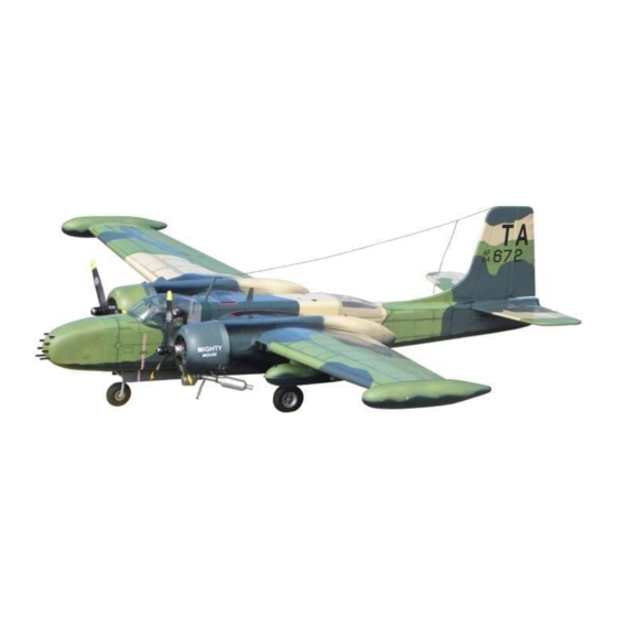
Radio control model / RC Motorflugmodell
A26K COUNTER INVADER
WINGSPAN: 68.in. / SPANNWEITER: 173cm
ASSEMBLY INSTRUCTION / AUFBAUANLEITUNG
TWIN .25 - .32 CLASS - 2 CYCLE ENGINE
TWIN .40 - .52 CLASS - 4 CYCLE ENGINE
ZWEITAKTMOTOREN:
VIERTAKTMOTOREN : 6.5 - 8.5cc (X2)
WARNING: This radio control model is not a toy. If modifier or flow carelessly, it could go out of
control and cause serious bodily injury or propety damage, It is you responsi-bility to build this kit
correctly, to properly install all components and to seek the help of an experi-enced R/C pilot for a
pre-flight safety inspection and test flying
Achtung: Dieses Modell ist kein Spielzeug!
Sollten Sie mit solch motorisiertem Modell keine Erfahrung haben, wenden
Sie sich bitte an erfahrene Modellflieger, die Sie unterstützen können.
Es könnte zu Verletzungen kommen, wenn das Modell ohne Vorkenntnisse
in Betrieb genommen wird. Denken Sie immer an die Sicherheit und Ihre Gesundheit.
4 - 5.2cc (X2)
Advertisement

Subscribe to Our Youtube Channel
Related Manuals for VQ Model A26K COUNTER INVADER


Summary of Contents for VQ Model A26K COUNTER INVADER
- Page 1 Radio control model / RC Motorflugmodell A26K COUNTER INVADER WINGSPAN: 68.in. / SPANNWEITER: 173cm ASSEMBLY INSTRUCTION / AUFBAUANLEITUNG TWIN .25 - .32 CLASS - 2 CYCLE ENGINE TWIN .40 - .52 CLASS - 4 CYCLE ENGINE ZWEITAKTMOTOREN: 4 - 5.2cc (X2) VIERTAKTMOTOREN : 6.5 - 8.5cc (X2)
- Page 2 REQUIRED FOR OPERATION (Purchase separately) BENOTIGTE KOMPONENTEN FUR DEN ABFLUG (Nicht enthalten) 9 x 7 for .32 - 2 cycle engine (x2) 10x7 for .52 - 4 cycle engine (x2) Silicone tube Minimum 6 channel radio for airplane / 6 servos. Throtle servo x2, Aileron servo x 2 Extension cord x 4 .40 ~ .52 cu.in.
- Page 3 1- Wing / Fläche Securely glue together, If coming off during flights, you lose control of your airplane which leads to accidents ! Vergewissern Sie sich, sauber geklebt zu haben Andernfalls konnen Probleme mit der Flugeigenschaft auftreten ! Wing joinner Tragflächenverbinder Use epoxy glue to bury the opening Nehmen Sie Epoxykleber, um die Tragflachen fest...
- Page 4 3.Engine / Motor In case of 4-cycle engine Viertaktmotoren Mark In case of 2-cycle engine Zweitaktmotoren 1/8” Note: Apply Silicon sealer to each of the screw and nut. Mark - Reposition the engine on the engine mount beams, aligning it with the holes.
- Page 5 5.Electric motor Using a aluminum motor mounting plate as a template, mark the plywood motor mounting plate where the four holes are to be drilled . Remove the aluminum motor mounting plate and drill a 5/32”(4mm) hole through the plywood at each of the four marks marked .
- Page 6 6.Electric motor Reposition the motor and secure it in place with eight 4mm nuts and washers. Note: B=B’(Side-view) and A=A’(Top-view) A=A’ A’ B’ Motorspant TOP-VIEW / Draufsicht SIDE-VIEW / Seitenansicht 7- Fixed gear / Fahrgestell 1/8x25/64” screw 3x10 mm screw 3x10mm schraube Kunststoffstreifen Nylon strap /...
-
Page 7: Typical Installation
8- Air Retract landing gear IN CASE OF 4T ENGINE (VIERTAKTMOTOREN) Einziehbares Fahrwerk (optional) 6x6mm Throttle servo mount hard wood (3mm plywood) IN CASE OF 2T ENGINE (ZWEITAKTMOTOREN) 6x6mm Throttle servo mount hard wood (3mm plywood) BOTTOM VIEW / UNTERSICHT Air retract landing gear (option) BOTTOM VIEW / UNTERSICHT... - Page 8 10- Electric Retract landing gear (optional) Main gear STEP STEP STEP INSTALLING THE ELECTRIC RETRACT: See Pic. 8 (Air Retract landing gear) 11- Shield / Motorgondel ABS top-left shield ABS top-right shield ABS rear shield ABS bottom-right shield Main landing gear 75mm wheel 4mm wheel collar 5/32”...
- Page 9 25/64”(10mm) Plastic control horn 12- Aileron servo / Hohenruderservo Use the fishing line inside each wing to lead the aileron and ......2 throttle servo extension cord all through the wing. 5/64x19/32” screw 2x15mm schraube ....4 WING - BOTTOM VIEW Fishing line 5/64x25/64”...
- Page 10 Höhenruder - Höhenleitwerk C = C’ D’ 14- Stabilizers / Trial fit each part before gluing . Be certain that there are no gaps. If the parts will join, but with a gaps, sand or trim the parts a little at a time until the parts meet exactly D’...
- Page 11 16- Installing the radio / Einbau RC-Anlage Elevator pushrod Retract servo here Rudergestänge Elevator servo Höhenruderservo Air tank here Rudder pushrod Rudder servo Seitenruderservo Elevator pushrod Nose gear pushrod (In case of mechanic retract) 3mm set Screw 3mm set Screw Gewindestift M3 Gewindestift M3 Elevator pushrod...
- Page 12 18- Linkages / Ruderanlenkung A-26 Rudder servo In case of mechanic retract landing gear Seitenruderservo 15/64x2” bolt 19-canopy / Kabinenhaube 6X50mm ...2 Nose gear servo tray 15/64x2” bolt (for electric retract) 5/64x13/64”screw 2x5mm schraube ....4 20- Linkages / Ruderanlenkung A-26 Nose gear servo In case of electric retract landing gear...
- Page 13 21- Nose gear (Fix gear) Bugfahrwerk 4mm nose gear 5/32” ID collar 4mm stellring 1/8x19/32” screw 3x15mm schraube Nose gear base (plastic) Nose gear arm ...4 Nose gear mount 1/8”(3mm) nut ....4 3x15mm screw 1/8”(3mm) nut Nose gear arm ....1 Nose gear pushrod 5/32”...
- Page 14 When you are satisfied with the alignment, use a pencil trace around the bottom of the 23- Wing shield wing shield where it meets the wing, Remove the wing shield from the wing, cut away the covering inside the pencil lines. Not to cut into the wood. Cut away only the covering Cut away only the covering...
- Page 15 26- Decor / Dekor FIRE EXTINGUISHER FIRE EXTINGUISHER NO STEP NO STEP NO STEP NO STEP A26 - VIET-NAM WAR - DECAL SHEET .VQ MODEL FIRE EXTINGUISHER CAUTION PROPELLER ROTATION...
Need help?
Do you have a question about the A26K COUNTER INVADER and is the answer not in the manual?
Questions and answers