Advertisement
Quick Links
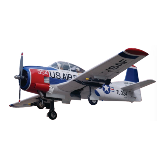
Instruction manual / Montageanleitung
SPECIFICATIONS
Wingspan:.....................................1870mm
Length:......................................... 1350mm
Electric Motor:.............900Watt - 80A. ESC
Glow Engine:..................120 4T / 75-95 2T
Gas Engine: ..................................17-20cc
RTF Weight: 5.3 - 5.6Kg (Will vary with
Equipment Used).
Radio:.................................See next pager
WARNING! This radio controlled model is NOT a toy. If modified or flown carelessly it could go out of controll and
cause serious human injury or property damage. Before flying your airplane, ensure the air field is spacious enough.
Always fly it outdoors in safe areas and seek professional advice if you are unexperienced.
ACHTUNG! Dieses ferngesteuerte Modell ist KEIN Spielzeug! Es ist für fortgeschrittene Modellflugpiloten bestimmt,
die ausreichende Erfahrung im Umgang mit derartigen Modellen besitzen. Bei unsachgemässer Verwendung kann
hoher Personen- und/oder Sachschaden entstehen. Fragen Sie in einem Modellbauverein in Ihrer Nähe um
professionelle Unterstätzung, wenn Sie Hilfe im Bau und Betrieb benötigen. Der Zusammenbau dieses Modells ist
durch die vielen Abbildungen selbsterklärend und ist für fortgeschrittene, erfahrene Modellbauer bestimmt.
Radio control model / Flugmodel
ALL BALSA, PLYWOOD CONSTRUCTION AND ALMOST READY TO FLY
All balsa and
plywood
Construction
Made in Vietnam
Advertisement

Related Manuals for VQ Model Trojan T-28


Summary of Contents for VQ Model Trojan T-28
- Page 1 Radio control model / Flugmodel ALL BALSA, PLYWOOD CONSTRUCTION AND ALMOST READY TO FLY Instruction manual / Montageanleitung All balsa and SPECIFICATIONS Wingspan:........1870mm plywood Length:......... 1350mm Electric Motor:.....900Watt - 80A. ESC Construction Glow Engine:....120 4T / 75-95 2T Gas Engine: ........17-20cc RTF Weight: 5.3 - 5.6Kg (Will vary with Equipment Used).
- Page 2 REQUIRED FOR OPERATION (Purchase separately) Extension cord for aileron servos: 60cm(x2) Extension cord for flap servos: 40cm(x2) 6 standard servos: Extension cord for retract servos: 40cm(x2) - Aileron: Extension cord for Rx battery pack: 30cm(x1) - Elevator: Extension cord for gear door servo: 30cm(x1) - Rudder: -Nose gear: 1...
-
Page 3: Glow Engine
1- Glow engine Attach the engine mount beams onto the fire-wall so the distance between of two engine mount beams is “A”. Secure the engine mount beams onto the fire-wall with litter CA glue. FRONT-VIEW ! Align the mark on both engine mount beams with the mark on the firewall. - Page 4 2- Glow engine Position the engine to the engine mounts so the distance from the prop hub to the fire-wall is 135mm (*). Mark the engine mounting plate where the four holes are to be drilled. Note: This distance (*) depends on the type of engine you use. Remove the engine and drill a 3mm holes through the beam at each of the four marks made above.
-
Page 5: Electric Motor
3- Electric motor Using a aluminum motor mounting plate as a template, Remove the aluminum motor mounting mark the plywood motor mounting plate where the four plate and drill a 3mm hole through holes are to be drilled. the plywood at each of the four marks marked . - Page 6 4- Electric motor Attach the four 5x80mm bolts 5x80mm bolt..4 and nuts to the fire-wall as shown. 5mm nut..12 5mm washer..16 Secure the Motor to the wooden motor mounting plate using the four 3mm hex bolts. 3mm bolt / nut...4 135mm Distance from the prop hub to the fire-wall is 135mm.
- Page 7 5- Fuel tank Blow Water Filler tube Rubber stopper 3x20mm bolt To engine Checking for leaks - block the vents and blow into the feed, After confirming the direction . Insert this assembly, clunk if in doubt submersing the tank in a blow of water will show end first, into the fuel tank and tighten and screw the fuel tank-cap on firmly.
- Page 8 6- Wing: extension cord & flap servo 30cm Extension cord Using the thread (pre-installed at factory) to slide the aileron extension cord into the wing half.
- Page 9 7- Wing: aileron servo Hard wood servo mount Thin CA ! Securely glue together. If coming off during fly, you lose control of your air plane. Threadlocker IMPORTANT: To be safe, you must attach the two 2x8mm screws as shown in this picture. 2x8mm screw servo hatch 2mm connector...
- Page 10 8- Wing: aileron and flap linkages Threadlocker 2x8mm self tapping screw 2x175mm push rod ..4 Plastic control horn ......4 2x30mm screw ......8 2mm connector ....2 2x8mm self tapping screw ....8...
- Page 11 9- Wing: wooden dowel Note: Make sure that the dowel must be perpendicular with the wing root before glue.
- Page 12 10- Wing: fixed gear assembling Insert the main landing gear into the slot on the gear mount, if necessary, use sander to widen the slot to Remove the nylon gear Reposition the nylon gear Using the nylon gear strap make this easier. strap and drill a 2mm hole strap and secure them in as a template, mark the...
- Page 13 11- Wing: fixed gear installation 3x12mm self tapping screw ..8...
- Page 14 12- Wing: fixed gear installation 4.2mm collar ..4 2x8mm self tapping screw ..4...
- Page 15 13- Wing: main gear housing cover 2x8mm self tapping screw ..16 14- Wing: Eretract landing gear Note: Eretract and strut must purchase separately GEAR SWITCH EXTENDED RETRACTED Make a key area with a file on music wire adapter. Extend retract with your transmitter and receiver or with servo driver.
- Page 16 15- Eretract assembling Fix the strut on the adapter..Fix the adapter in the retract with hexagon socket screws supplied with scale oleo strut..then tighten the locking bolt. Slip the wheel on the axle with the circlip pointing away from the strut... Attach the axle to the gear and tighten the locking bolt (use LOCTITE threadlocker on every bolt).
- Page 17 16- Eretract installation...
- Page 18 17- Eretract: Radio connection & operation Radio connection 1-Plug the connector from each of the retract unit into the 2 in 1 wire harness (not supplied). 2-Plug the single lead from the wire hardness into the gear channel of your receiver. An auxiliary channel can be used if the gear channel is occupied.
- Page 19 19- Gear door GEAR SWITCH RETRACTED Connect the electric retract with the radio to check the position of the wheel and the gear door when the electric retract in retracted position. Ensure smooth non-binding movement. When satisfied, secure the wooden gear door mount in place using CA glue.
- Page 20 20- Canon adaptable & external load support H-RK...
- Page 21 21- Canon adaptable & external load support...
-
Page 22: Horizontal Stabilizer
22- Canon adaptable & external load support Note: Detail such as pilot, pilot’s seat, rockets, instrument panels...are printed from a 3D printer with an environmentally friendly plastic (PLA) made from cornstarch, it will the decompose after about 3 years from the date of produced. 23- Horizontal stabilizer Cut away only the covering both sides... - Page 23 24- Horizontal stabilizer Insert the horizontal stabilizer into the slot on the fuselage, if necessary, use sander to widen the slot to make this easier. Cut away only the covering. Check the alignment of the horizontal stabilizer by measuring from the fixed point along the center line of the fuselage to the trailing edge of the horizontal stabilizer The distance must be equal on both sides.
- Page 24 24- Horizontal stabilizer Insert the horizontal stabilizer into the slot on the fuselage, if necessary, use sander to widen the slot to make this easier. Cut away only the covering. Check the alignment of the horizontal stabilizer by measuring from the fixed point along the center line of the fuselage to the trailing edge of the horizontal stabilizer The distance must be equal on both sides.
-
Page 25: Vertical Stabilizer
25- Horizontal stabilizer Use a small glue faucet, Apply the thin CA glue on the horizontal stabilizer where it contacts the fuselage (both the top and bottom sides),and into the slot of the fuselage as show. ! Securely glue together. If coming off during fly, you lose control of your air plane. - Page 26 29- Nose Eretract & strut Note: Eretract and strut must purchase separately Nose gear servo 3x15mm self tapping screw...
- Page 27 29- Nose Eretract & strut Note: Eretract and strut must purchase separately Nose gear servo 3x15mm self tapping screw...
- Page 28 30- Nose fixed gear ..1 Nose gear Nose gear mount ..1 Nose gear arm ..1 1.2x500mm Nose gear push-rod ..1 2.5x500mm Nylon push-rod guide tube 3x20mm hex bolt -washer - blind nut ..4 2mm connector ..1 4.2mm collar ..2...
- Page 29 31- Nose gear housing cover 2x8mm self tapping screw ..9 32- Nose gear housing door...
- Page 30 33- Nose gear housing door Fuselage Spring Thread Position of gear doors when retract gear in extended. Fuselage Position of gear doors when retract gear in retracted. 34- Air exhaust vent...
- Page 31 35- Exhaust pipes Aluminum tube 36- Dummy engine Secure the dummy engine in place with CA glue.
- Page 32 37- Cowling 2x8mm self tapping screw ..6 5 min.epoxy...
- Page 33 38- Main gear door & linkage Gear door push-rod Gear door servo Gear door push-rod Bend the gear door push rod for smooth work.
- Page 34 39- Linkages Elevator servo Elevator servo Gear door servo Rudder servo Threadlocker...
-
Page 35: Joining The Wing
40- Tail hatch 2x8mm self tapping screw ..6 41- Joining the wing... -
Page 36: Canopy Hatch
42- Joining the wing 7mm dia. nylon bolt 7mm dia. nylon bolt ..2 43- Canopy hatch 4x30mm nylon bolt 4x30mm nylon bolt ..2... - Page 37 44- Sticker T-28 “Huff “n” Puff” Version T-28 “Huff “n” Puff” Version T-28 U.S.A.F White-red-blue Version...
- Page 38 45- Balance THE CENTER OF GRAVITY IS LOCATED 126mm BACK FROM THE LEADING EDGE OF THE WING, AT THE FUSELAGE. BALANCE A PLANE UPSIDE DOWN WITH THE FUEL TANK EMPTY. 126mm 1- Mount the wing to the fuselage. Using a couple of pieces of masking tape, place them on the top side of the wing (126mm) back from the leading edge, at the fuselage sides.
Need help?
Do you have a question about the Trojan T-28 and is the answer not in the manual?
Questions and answers