Table of Contents
Advertisement
RADIO CONTROL MODEL / RC FLUGMODELL
BUILDING INSTRUCTIONS / MONTAGEANLEITUNG
Specification:
Wingspan
Length
54.1 in.(Canada version)
56.5 in. (Swiss version)
Flying weight
Motor
Radio
Technische Daten:
Spannweite
Länge
1.375mm (Canada version)
1.435mm (Swiss version)
Fluggewicht
Verbrennerantrieb
# C9493 Antriebsset Brushless f.
Fernsteuerung
# C8802 Fernsteuerung GigaProp 6
WARNING! This radio controlled model is NOT a toy. If modified or flown carelessly it could go out of controll and
cause serious human injury or property damage. Before flying your airplane, ensure the air field is spacious enough.
Always fly it outdoors in safe areas and seek professional advice if you are unexperienced.
ACHTUNG! Dieses ferngesteuerte Modell ist KEIN Spielzeug! Es ist für fortgeschrittene Modellflugpiloten bestimmt,
die ausreichende Erfahrung im Umgang mit derartigen Modellen besitzen Bei unsachgemäßer Verwendung kann
hoher Personen- und/oder Sachschaden entstehen. Fragen Sie in einem Modellbauverein in Ihrer Nähe um
professionelle Unterstützung, wenn Sie Hilfe im Bau und Betrieb benötigen. Der Zusammenbau dieses Modells ist
durch die vielen Abbildungen selbsterklärend und ist für fortgeschrittene, erfahrene Modellbauer bestimmt.
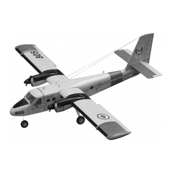
DHC-6
Semi scale model
VQA138SW
72.4 in.
7.5 lbs
See next pager
See next pager
1.840mm
3.400g
VQA138CA
Advertisement
Table of Contents

Subscribe to Our Youtube Channel
Related Manuals for VQ Model VQA138SW


Summary of Contents for VQ Model VQA138SW
- Page 1 DHC-6 Semi scale model RADIO CONTROL MODEL / RC FLUGMODELL BUILDING INSTRUCTIONS / MONTAGEANLEITUNG VQA138CA VQA138SW Specification: Wingspan 72.4 in. Length 54.1 in.(Canada version) 56.5 in. (Swiss version) Flying weight 7.5 lbs Motor See next pager Radio See next pager...
-
Page 2: Conversion Table
Sonderzubehör (empfohlen) / Opional Accessories (recommended): 2x # C5185 MASTER SERVO S2112 2x # C5638 MASTER SERVO S3012MG 2x # C1687 MASTER SERVO S4020 # C6788 LiPo Akku RED POWER 4500-11.1V # C8802 Fernsteuerung GigaProp 6 Radio Set GigaProp 6 # C9493 Antriebsset Brushless f. -
Page 3: Motor Mount
1- Motor mount Cut away only the covering Carefully, push the Motor mounting onto the slot on the wing as shown. WING (Top side) Check the mark on the motor mounting with the surface of the wing before glue. Using the thin CA glue WING (Top side) MOTOR MOUNT - SIDE VIEW... - Page 4 2- Motor mount WING (Bottom side) WING (Bottom side) 2x8mm self tapping screw WING (Top side) 2x8mm self tapping screw 2x8mm self tapping screw .....28...
-
Page 5: Wing: Servo
3- Cowling 2x8mm self tapping screw .....4 2x8mm self tapping screw Wing 4- Wing: servo Plastic control horn .....2 Linkage Stopper set 3mm set Screw Thin CA ....2 ..2 2x175mm pushrod Aileron and Flap pushrod Note: The rectangular hole 2 mm for the control horn installation is pre- cut at factory. -
Page 6: Main Landing Gear
5- Main landing gear 3x15mm screw 4x20mm plastic bolt Turn the 4x20mm plastic bolt inside the fuselage and move the landing gear hatch. 2x8mm self tapping screw Slide the ABS landing gear cover onto the aluminum landing gear and secure it in place using 2x8mm self tapping screws. -
Page 7: Nose Landing Gear
6- Nose landing gear Flat Route the steering linkage into the fuselage and through the fire-wall. 3x20mm screw Glue the outer tube in place as shown. Attach the nose gear mount onto the fire-wall and secure it in place using Insert “Z”... -
Page 8: Top View
7- Stabilizer Slowly, slide the horizontal stabilizer through the vertical stabilizer. Check the alignment of the horizontal stabilizer, the distance must be equal on both sides (A=A’). When you are satisfied with the alignment, use a pencil to trace around the top and bottom of the horizontal stabilizer where it meets the vertical stabilizer. - Page 9 8- Stabilizer Continued Again, slide the horizontal stabilizer through the vertical stabilizer. With the perpendicular, check the alignment of the vertical stabilizer and the horizontal stabilizer during glue. ! Securely glue together. If coming off during fly, you lose control of your air plane. Vertical stabilizer Thin CA Perpendicular...
- Page 10 9- Stabilizer Continued Using a sharp hobby knife, carefully cut away the covering inside the lines which were marked above. Be cautious not to cut into the wood-this will weaken the structure. Cut away only the covering and inside Thin CA Again, slide the holder onto the horizontal stabilizer the line Apply the thin CA glue on the vertical stabilizer...
- Page 11 - Stabilizer Continued When you are satisfied with the alignment, use a sharp hobby knife, carefully cut the covering where the vertical stabilizer meet the fuselage. Be cautious not to cut into the wood - this will weaken the structure. Carton template Carton template Remove the vertical stabilizer from the fuselage...
-
Page 12: Horizontal Stabilizer
Rudder and Elevator Cut away only the covering Thin CA Note: The rectangular holes are pre-laser cut at factory Cut away only TOP-SIDE the covering HORIZONTAL STABILIZER Thin CA Apply a thin layer of petroleum jelly Apply thin CA glue on the top of the hinge ! Securely glue together. -
Page 13: Wing Installation
Wing installation Slowly, push the aluminum tube through the fuselage. Note: Push the top hatch to the side of the fuselage and full it to remove. Carefully, push the wing to the fuselage as shown. - Page 14 Wing installation 4x25mm plastic bolt When the wing meet the fuselage with no gap, secure the wing in place using the 4x25mm plastic bolt. Servo and Linkages Elevator push-rod Rudder push-rod Elevator push-rod 2 mm FUSELAGE - TOP VIEW To nose gear arm Nylon pushrod guide To rudder control horn To left elevator control horn...
- Page 15 Shield and Wing brace 2x8mm self tapping screw ...4 The rectangular hole on the fuselage is pre-laser cut at factory. Cut away only the covering. 3mm blind nut ...2 3x15mm screw ..2 3x12mm self tapping screw ...2 Decal Decal of Otter Canada version Decal of Otter Swiss version Decal application: See the label on top box Note: Cut out the stickers and apply them in the proper area.
-
Page 16: Control Surface
Control Surface Aileron Querruderausschlag 12mm 12mm 25mm Rudder Flap Seitenruderausschlag 25mm 18mm Do not try to fly an out-of balance model! Uberprufen Sie vor dem Flug den Schwerpunkt. Elevator 15mm 56 ~ 60mm 15mm Hohenruderausschlag Adjust the travel of the control surfaces to achieve the values stated in the diagrams. These value will be suitable for average flight requirements.
Need help?
Do you have a question about the VQA138SW and is the answer not in the manual?
Questions and answers