Table of Contents
Advertisement
Quick Links
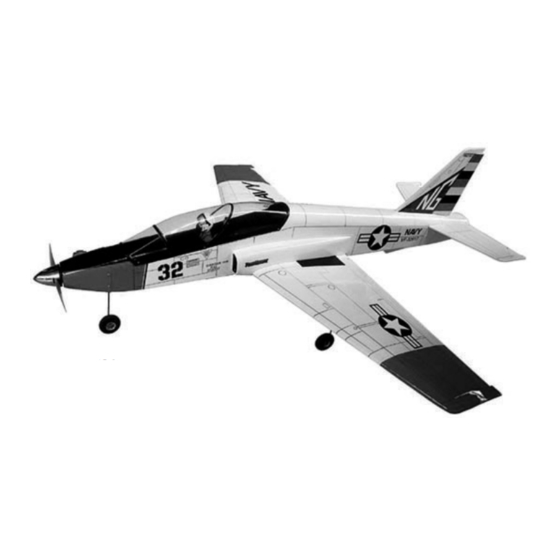
RADIO CONTROL MODEL / RC FLUGMODELL
Instruction manual / Montageanleitung
ALL BALSA, PLYWOOD CONSTRUCTION AND ALMOST READY TO FLY
VQA023
TECHNISCHE DATEN
Spannweite
Elektroantrieb
870 Watt (PULSAR 60)
Verbrennerantrieb
Fernsteuerung
WARNING! This radio controlled model is NOT a toy. If modified or flown carelessly it could go out of controll and
cause serious human injury or property damage. Before flying your airplane, ensure the air field is spacious enough.
Always fly it outdoors in safe areas and seek professional advice if you are unexperienced.
ACHTUNG! Dieses ferngesteuerte Modell ist KEIN Spielzeug! Es ist für fortgeschrittene Modellflugpiloten bestimmt,
die ausreichende Erfahrung im Umgang mit derartigen Modellen besitzen Bei unsachgemäßer Verwendung kann
hoher Personen- und/oder Sachschaden entstehen. Fragen Sie in einem Modellbauverein in Ihrer Nähe um
professionelle Unterstützung, wenn Sie Hilfe im Bau und Betrieb benötigen. Der Zusammenbau dieses Modells ist
durch die vielen Abbildungen selbsterklärend und ist für fortgeschrittene, erfahrene Modellbauer bestimmt.
Sport " JET"
SPECIFICATIONS
1372mm
7.5cc 2-T
4 Kanal / 4 Servos
Wingspan
Electric Motor
870 Watt (PULSAR 60)
Glow Engine
Radio
4 Channel / 4 Servos
1372mm
46 2-T
Advertisement
Table of Contents

Subscribe to Our Youtube Channel
Related Manuals for VQ Model TOMHAWK


Summary of Contents for VQ Model TOMHAWK
- Page 1 RADIO CONTROL MODEL / RC FLUGMODELL Sport “ JET” Instruction manual / Montageanleitung ALL BALSA, PLYWOOD CONSTRUCTION AND ALMOST READY TO FLY VQA023 SPECIFICATIONS TECHNISCHE DATEN Wingspan 1372mm Spannweite 1372mm Electric Motor 870 Watt (PULSAR 60) Elektroantrieb 870 Watt (PULSAR 60) Glow Engine 46 2-T Verbrennerantrieb...
- Page 2 REQUIRED FOR OPERATION (Purchase separately) 10.5x6 for .40 - 2 cycle engine Extension for aileron 11x6 for .46 - 2 cycle engine servo, retract servo. 12x6 for .60 - 4 cycle engine 12x7 for .70 - 4 cycle engine 13x6 for Quantum 4120/05 Phoenix-60 Brushless Motor Control Minimum 4 channel radio...
-
Page 3: Bottom View
1- RETRACT LANDING GEAR 3x10mm screw ..X 8 Trial fit the push rod into the wing. Join the pushrod to the retract gear arm and trial fit the retract into the wing. (3x10) screw BOTTOM VIEW After checking that the retract works smoothly, fix the retract on the wing with 3x12mm self tapping screws. -
Page 4: Joining The Wing
Trial fit each part before gluing . Be certain that there are no gaps. 4- JOINING THE WING If the parts will join, but with a gaps, sand or trim the parts a little at a time until the parts meet exactly with no gaps. BOTTOM VIEW When joining the wing halves it is extremely important to use plenty of epoxy (30 minutes epoxy). -
Page 5: Installing The Linkages
6- RETRACT - AILERON SERVO Aileron servo Included with the radio set WING - TOP VIEW Retract servo 2 mm 20 ~ 24mm 1.5mm Retract servo Retract Push rod Link the retract push rod to the retract servo. Be sure to adjust the stroke so that the landing gear locks in both up and down position. - Page 6 8- ENGINE MOUNT - NOSE GEAR MOUNT ! Engine thrust on balk head ! Align the mark on both 4x15mm screw is already adjust at factory mounts with the mark on ....4 the fire wall Washer.....4 Blind nut..4 13/64” 3x20mm screw ....4 4 - 5 Washer....4...
-
Page 7: Fuel Tank
10- ENGINE (2 CYCLE) FUSELAGE TOP-VIEW Silencer A=4-9/32” ~ 4-23/64” (108~110mm) FUSELAGE FRONT-VIEW 11- FUEL TANK After confirming the direction . Insert this assembly, clunk To muffler end first, into the fuel tank and tighten and screw the Filler tube fuel tank cap on firmly Rubber stopper... -
Page 8: Horizontal Stabilizer
12- HORIZONTAL STABILIZER Trial fit the horizontal stabilizer in place on the fuselage. Check the alignment of the horizontal stabilizer by measuring from a fixed point along the center line of the fuselage to the leading edge Cut away only the covering on each side of the horizontal stabilizer. - Page 9 15- HORIZONTAL STABILIZER Slide the horizontal stabilizer partially into the fuselage, marking sure that the top of the ho- rizontal stabilizer is toward the top of the fuse- lage. Apply a thin layer of petroleum jelly to only the pivot point of the torque rod bearing, then slide the adjustable control horn through the side of the fuselage and glue the torque rod bearing into the slot you cut previously in the horizontal...
-
Page 10: Vertical Stabilizer
Cut away only the 18- VERTICAL STABILIZER Rudder torque rod covering material (long piece) Rudder push rod Slide the rudder torque rod into the fuselage. Link the rudder torque rod with the rudder push rod. Remove the covering material from over both side of 19- VERTICAL STABILIZER the vertical stabilizer where it meet the fuselage. - Page 11 21- LINKAGES Elevator servo (not include) Rudder control horn Rudder push rod Elevator control horn Connector FUSELAGE - BOTTOM VIEW To nose gear horn Rudder servo (not include) 22- LINKAGES Rudder push rod To nose retract To engine Throttle servo (not include) FUSELAGE - BOTTOM VIEW Retract servo (not include) 23- COWLING...
- Page 12 6x45mm nylon screw 24- MAIN WING 1/4 in. 6.3mm Plastic cover BOTTOM VIEW 25-CANOPY 5/64” 2x5mm screw ....6 Secure the canopy in place using the six 2x5mm self tapping screws included the hardware bag. Apply CA glue into the screwed hole to make 3/64”...
- Page 13 27- RECEIVER Receiver FUSELAGE - BOTTOM VIEW 28- CONTROL SURFACE THROW SETTING 5~8mm 30mm 8~10mm 8~10mm 5~8mm 30mm RUDDER STROKE AILERON STROKE ELEVATOR STROKE 29- BALANCE WARNING ! Securely install the receiver and power pack, ensuring they will not come loose or rattle during flight.
Need help?
Do you have a question about the TOMHAWK and is the answer not in the manual?
Questions and answers