Table of Contents
Advertisement
Quick Links
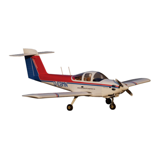
PA-38
Instruction manual / Montageanleitung
SPECIFICATIONS
Wingspan:.....................................1920mm
Length:......................................... 1320mm
Electric Motor:.............900Watt - 80A. ESC
Glow Engine:.........................91 4T / 60 2T
Gas Engine: .......................................17cc
RTF Weight: 4.1 - 4.5Kg (Will vary with
Equipment Used).
Radio:.................................See next pager
WARNING! This radio controlled model is NOT a toy. If modified or flown carelessly it could go out of controll and
cause serious human injury or property damage. Before flying your airplane, ensure the air field is spacious enough.
Always fly it outdoors in safe areas and seek professional advice if you are unexperienced.
ACHTUNG! Dieses ferngesteuerte Modell ist KEIN Spielzeug! Es ist für fortgeschrittene Modellflugpiloten bestimmt,
die ausreichende Erfahrung im Umgang mit derartigen Modellen besitzen. Bei unsachgemässer Verwendung kann
hoher Personen- und/oder Sachschaden entstehen. Fragen Sie in einem Modellbauverein in Ihrer Nähe um
professionelle Unterstätzung, wenn Sie Hilfe im Bau und Betrieb benötigen. Der Zusammenbau dieses Modells ist
durch die vielen Abbildungen selbsterklärend und ist für fortgeschrittene, erfahrene Modellbauer bestimmt.
Radio control model / Flugmodel
Tomahawk
All balsa and
plywood
Construction
Advertisement
Table of Contents

Related Manuals for VQ Model Tomahawk PA-38


Summary of Contents for VQ Model Tomahawk PA-38
- Page 1 Radio control model / Flugmodel PA-38 Tomahawk Instruction manual / Montageanleitung All balsa and SPECIFICATIONS Wingspan:........1920mm plywood Length:......... 1320mm Electric Motor:.....900Watt - 80A. ESC Construction Glow Engine:......91 4T / 60 2T Gas Engine: ........17cc RTF Weight: 4.1 - 4.5Kg (Will vary with Equipment Used).
- Page 2 REQUIRED FOR OPERATION (Purchase separately) 12x6 for .60 - 4 cycle engine Servo extension cord: 13x7 for .90 - 4 cycle engine Aileron: 50mm x2 pcs 14X8 for Electric Motor. Flap: 30mm x2 pcs Elevator: 40mm x4 pcs Rudder: 20mm x1 pc Rx battery: 20mm x1 pc .60 - 2 cycle .90 - 4 cycle...
- Page 3 1- Extension cord & Servo PA-38 Tomahawk 30cm Extension cord Using the thread (pre-installed at factory) to slide the aileron extension cord into the wing half. 50cm Extension cord Threadlocker 2mm connector ..2...
- Page 4 2- Control horn & Linkages PA-38 Tomahawk The rectangular holes were cut out at the factory. cut away only the covering 2x175mm flap rod with clevis ...2 2x175mm aileron rod with clevis and EZ link ...2 Control horn ......2 Control horn ....2 set...
- Page 5 3x15mm hex bolt ...4 2x8mm screw ..12...
- Page 6 4- Main wheel & Dowel PA-38 Tomahawk 75mm wheel 4mm nut 4mm nut ...2 4x45mm screw 4X40mm screw ...2 Aluminum landing gear 4mm nut ....4 4mm washer ....6 Thin CA Note: Make sure that the dowel must be perpendicular with the wing root before glue. Thin CA...
-
Page 7: Nose Gear Installation
5- Nose gear installation PA-38 Tomahawk 3x20mm hex bolt ...4 1- Drill the 2.5mm hole on the firewall where the nylon pushrod guide will go through . 2- Insert the nylon pushrod guide and nose gear push rod through the firewall as shown. 3- Insert the “Z”... -
Page 8: Engine Mount
6- Engine mount PA-38 Tomahawk The center of the engine axis and the angle of inclination of the firewall have been designed ! Align the mark on both engine mount beams with the mark on the fuselage correctly, should not be modified. Mark on the firewall B’... - Page 9 7- Engine PA-38 Tomahawk Position the engine to the engine mounts so the distance from the prop hub to the fire-wall is 133mm (*). Mark the engine mounting plate where the four holes are to be drilled. Note: This distance (*) depends on the type of engine you use.
- Page 10 8- Electric motor mount PA-38 Tomahawk Remove the aluminum motor mounting Using a aluminum motor mounting plate plate and drill a 3mm hole through the as a template, mark the plywood motor plywood at each of the four marks mounting plate where the four holes are marked .
- Page 11 8- Electric motor mount PA-38 Tomahawk 5x80mm bolt..4 5mm nut..12 5mm washer...16 Attach the four 5x80mm bolts and nuts to the fire-wall as shown. 133mm Position the motor mount to so the distance from the prop hub to the fire-wall is 133mm .
- Page 12 9- Elevator servo mount PA-38 Tomahawk 2mm connector Threadlocker ..2...
-
Page 13: Horizontal Stabilizer
10- Horizontal stabilizer PA-38 Tomahawk HORIZONTAL STABILIZER VERTICAL STABILIZER When you are satisfied with the alignment, use a pencil to trace around the right and left of the stabilizer where it meets the vertical stabilizer. - Page 14 11- Horizontal stabilizer PA-38 Tomahawk continued Remove the horizontal stabilizer from the fuselage. Cut away only Using the sharp hobby knife, carefully cut away the the covering covering inside the lines which were marked above. Be cautious not to cut into the wood, this will weaken the structure.
- Page 15 12- Rudder PA-38 Tomahawk Thin CA ! Securely glue together. If coming off during fly, you lose control of your air plane.
- Page 16 13- Attach the stabilizer to the fuselage PA-38 Tomahawk When you are satisfied with the alignment, use a pencil to trace around the right and left of the stabilizer where it meets the fuselage.
- Page 17 14- Attach the stabilizer to the fuselage PA-38 Tomahawk continued Remove the stabilizer from the fuselage. Using the sharp hobby knife, carefully cut away the covering inside the lines which were marked above. Be cautious not to cut into the wood, this will weaken the structure.
-
Page 18: Elevator Linkage
15- Elevator linkage PA-38 Tomahawk 1.5x175mm rod ...2... - Page 19 16- Rudder - Nose gear - Throttle linkages linkage PA-38 Tomahawk pull up to move 2x950mm Rudder push-rod ..1 1.2x550mm Nose gear / Throttle push-rod ..2 2mm connector Threadlocker ..3 Nose gear servo Rudder servo Throttle servo...
- Page 20 17- Joining the wing PA-38 Tomahawk 7mm dia. plastic bolt ..2...
- Page 21 18- Joining the wing PA-38 Tomahawk Blow Filler tube Water To muffler Rubber stopper 3x20mm bolt To engine Clunk After confirming the direction . Insert this assembly, clunk Checking for leaks - block the vents and blow into the feed, end first, into the fuel tank and tighten and screw the fuel if in doubt submersing the tank in a blow of water will show tank-cap on firmly.
- Page 22 19- Cowling - Sticker PA-38 Tomahawk 1.5mm 2.5x10mm screw ..6 4x20mm plastic bolt ..2 Sticker Sticker Sticker Sticker IMPORTANT: Please do not clean your model with strong solvent or pure alcohol, only use kerosene to keep the colour of your model not fade.
-
Page 23: Control Surface
20- Balance - Control surface PA-38 Tomahawk THE CENTER OF GRAVITY IS LOCATED 62mm BACK FROM THE LEADING EDGE OF THE WING, AT THE FUSELAGE. BALANCE A PLANE UPSIDE DOWN WITH THE FUEL TANK EMPTY. C=62mm 1- Mount the wing to the fuselage. Using a couple of pieces of masking tape, place them on the top side of the wing (62mm) back from the leading edge, at the fuselage sides.
Need help?
Do you have a question about the Tomahawk PA-38 and is the answer not in the manual?
Questions and answers