Advertisement
Quick Links
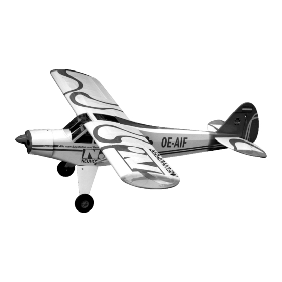
Radio control model
R/C Flugmodell
INSTRUCTION MANUAL
MONTAGEANLEITUNG
TECHNISCHE DATEN
Spannweite
Lange
Elektroantrieb
(siehe nächste Seite)
Verbrennerantrieb
Fernsteuerung
6 Kanal / 8 Servos
WARNING! This radio controlled model is NOT a toy. If modified or flown carelessly it could go out of controll and
cause serious human injury or property damage. Before flying your airplane, ensure the air field is spacious enough.
Always fly it outdoors in safe areas and seek professional advice if you are unexperienced.
ACHTUNG! Dieses ferngesteuerte Modell ist KEIN Spielzeug! Es ist für fortgeschrittene Modellflugpiloten bestimmt,
die ausreichende Erfahrung im Umgang mit derartigen Modellen besitzen Bei unsachgemäßer Verwendung kann
hoher Personen- und/oder Sachschaden entstehen. Fragen Sie in einem Modellbauverein in Ihrer Nähe um
professionelle Unterstützung, wenn Sie Hilfe im Bau und Betrieb benötigen. Der Zusammenbau dieses Modells ist
durch die vielen Abbildungen selbsterklärend und ist für fortgeschrittene, erfahrene Modellbauer bestimmt.
SPECIFICATIONS
Wingspan
2710mm
Length
1720mm
Electric Motor
Glow Engine
26-30cc 2-T
Radio
PIPER PA-18
SUPER CUB
106.6in.
67.7 in.
(See next page)
26-30cc two stroke
6 Channel / 8 Servos
ARF BY
Advertisement

Related Manuals for VQ Model PIPER PA-18 SUPER CUB


Summary of Contents for VQ Model PIPER PA-18 SUPER CUB
- Page 1 Radio control model PIPER PA-18 R/C Flugmodell INSTRUCTION MANUAL SUPER CUB MONTAGEANLEITUNG ARF BY TECHNISCHE DATEN SPECIFICATIONS Wingspan 106.6in. Spannweite 2710mm Length 67.7 in. Lange 1720mm Electric Motor (See next page) Elektroantrieb (siehe nächste Seite) Glow Engine 26-30cc two stroke Verbrennerantrieb 26-30cc 2-T Radio...
- Page 2 REQUIRED FOR OPERATION (Purchase separately) BENOTIGTE KOMPONENTEN FUR DEN ABFLUG (Nicht enthalten) Extension for aileron servo, Flap servo. Gas Engine: 26 ~ 30cc Minimum 6 channel radio Nylon tube for airplane with 8 servos .Motor control x1 .Aileron x2 .Elevator x2 .Rudder x1 .Flap x 2 GLUE (Purchase separately) Epoxy Glue (5 minute type)
- Page 3 HORIZONTAL STABILIZER - VERTICAL STABILIZER TOP VIEW / Draufsicht Full the elevator out of the Cut two slots (only the covering) on the horizontal stabilizer. top and along the trailing edge of the horizontal stabilizer. HORIZONTAL STABILIZER TOP VIEW / Draufsicht 35mm 35mm 19mm...
- Page 4 Pull the horizontal stabilizer through the other side of the fuselage and repeat the previous procedures to glue the second torque rod wire into the horizontal Cut away only the covering stabilizer. on the top and bottom Realign the horizontal stabilizer, then glue the horizontal stabilizer into the fuselage, using a generous amount of thin CA.
-
Page 5: Tail Wheel
Trial fit the vertical stabilizer in place . Check the alignment of the vertical stabilizer. When you are satisfied with the alignment, use a pencil to trace around the right and left of the stabilizer where it meets the fuselage. Cut away only the covering on the left and right side. -
Page 6: Main Landing Gear
MAIN LANDING GEAR BOTTOM - VIEW / Unteransicht 4X20mm screw ..6 Cut away only the covering * WARNING: When removing any covering from the airframe, please ensure that you secure the cut edge with CA or similar cement. This will ensure the covering remain tight. BOTTOM - VIEW / Unteransicht MAIN LANDING GEAR MAIN LANDING GEAR... - Page 7 MAIN LANDING GEAR 4X40mm screw ....2 4mm nut-washer BOTTOM - VIEW / Unteransicht 4mm nut 4mm nut 4x30mm 4x30mm screw screw 3mm connector Aluminum landing Aluminum landing gear Hauptfahrwerk gear Hauptfahrwerk FUSELAGE MAIN LANDING GEAR ...1...
- Page 8 ENGINE Using a aluminum motor mounting plate as a template, mark the fire-wall where the four holes are to be drilled (1). Remove the aluminum motor mounting plate and drill a 5mm hole through the plywood at each of the four marks marked (2). Aluminum motor mounting plate Note: The aluminum motor mounting and screws included with the engine.
-
Page 9: Electric Motor
ELECTRIC MOTOR Using a aluminum motor mounting plate as a template, mark the fire-wall where the four holes are to be drilled (1). Remove the aluminum motor mounting plate and drill a 5mm hole through the plywood at each of the four marks marked (2). - Page 10 FUEL TANK & LIPO. BATTERY Fuel tank flat (3mm plywood) Fuel tank seat bell 30cc Fuel tank Tipp Fuel tank seat bell Akku Kiettband aus dem PICHLER Sortiment Fuel tank assembly Best.Nr. C4739 Li-po battery...
- Page 11 SERVO Servo tray IN CASE OF THE ELEVATOR SERVO IN SIDE OF THE FUSELAGE IN CASE OF THE ELEVATOR SERVO OUT SIDE OF THE FUSELAGE SERVO TRAY - TOP VIEW Servo tray Elevator servo FRONT Elevator FUEL TANK pushrod Rudder Throttle servo pushrod Throttle...
-
Page 12: Wing Section
Control horn SERVO ......4 Flap servo Servo mount 2x30mm screw 2x10mm ....8 screw 1.5mm Connector ....4 Flap servo hatch WING BOTTOM Aileron servo 2x10mm Servo mount 1.5mm screw Aileron servo hatch WING BOTTOM Aileron, flap servo and light extension cord not include. BOTTOM - VIEW / Unteransicht 2X30mm Aileron servo and hatch... - Page 13 WING BOTTOM - VIEW / Unteransicht Cut away only the covering Assemble left and right wing halves the same way WING Aluminum tube Slide the aluminum tube into the fuselage as shown. Do the same way with other wing halves.
- Page 14 WING Secure the wing halves in place using 5x20mm screw. Do the same way with other wing halves. 5x20mm ..2 5mm washer ....2 WING FRONT Cut away only the covering LEFT BRACE (TOP VIEW) FRONT RIGHT BRACE (TOP VIEW) BOTTOM - VIEW / Unteransicht ..4 WING 3x12mm...
- Page 15 TAIL Stabilizer TAIL 0.7mm dia. Cable ...1 roll 2mm metal tube .....4 TAIL ....2 3x6..2 2mm metal tube BOTTOM - VIEW ....4 Unteransicht...
- Page 16 LIGH 2x6mm ..6 DECOR BURDA VERSION AUSTRIA VERSION Note: Cut out the stickers and apply them in the proper area. Do not peel the backing paper off all at once. Peel off one corner of the backing and cut off with scissors.
Need help?
Do you have a question about the PIPER PA-18 SUPER CUB and is the answer not in the manual?
Questions and answers
I have the 46 sized cub and I **** having some problems with installing the engine mounts. The height of the mount is not a problem but the left/right positioning of the mounts is not clear. The vertical line on the bulkhead is not central, is that correct. Please see photo.
The aluminum motor mounting plate should be used as a template to mark the fire-wall where the four holes need to be drilled. After marking, remove the plate and drill a 5mm hole through the plywood at each of the four marks. The aluminum motor mounting and screws are included with the engine. The mounting position should ensure that B = 152-158mm.
This answer is automatically generated
@Mr. Anderson
Thank you for your response but my question is , does the engine have to be mounted off centre?