Table of Contents
Advertisement
Instruction manual / Montageanleitung
SPECIFICATIONS
Wingspan:.........................1760mm (69.2in)
Length:.............................1210mm (47.6 in)
Electric Motor:.....................See next pager
Glow Engine:.................... Twin 40 - 2T
RTF Weight: 4.3Kg / 9.5lbs (Will vary with
Equipment Used).
Radio:......................6 Channel / 7-8 Servos
Function: Ailerons-Elevator-Rudder-Throttle
Flaps-Optional Retractable Landing Gear.
WARNING! This radio controlled model is NOT a toy. If modified or flown carelessly it could go out of controll and
cause serious human injury or property damage. Before flying your airplane, ensure the air field is spacious enough.
Always fly it outdoors in safe areas and seek professional advice if you are unexperienced.
ACHTUNG! Dieses ferngesteuerte Modell ist KEIN Spielzeug! Es ist für fortgeschrittene Modellflugpiloten bestimmt,
die ausreichende Erfahrung im Umgang mit derartigen Modellen besitzen. Bei unsachgemässer Verwendung kann
hoher Personen- und/oder Sachschaden entstehen. Fragen Sie in einem Modellbauverein in Ihrer Nähe um
professionelle Unterstätzung, wenn Sie Hilfe im Bau und Betrieb benötigen. Der Zusammenbau dieses Modells ist
durch die vielen Abbildungen selbsterklärend und ist für fortgeschrittene, erfahrene Modellbauer bestimmt.
Radio control model / Flugmodel
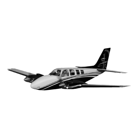
BEECHCRAFT
BARON
VQ No: VQA157USAR - VQA157US
ALL BALSA, PLYWOOD CONSTRUCTION AND ALMOST READY TO FLY
TECHNISCHE DATEN
Spannweite:...................................1760mm
Lange:............................................1210mm
Elektroantrieb.............(siehe nächste Seite)
Verbrennerantrieb:........................7.45cc 2T
Fluggewicht:.......................................4.3Kg
Fernsteuerung.............6 Kanal / 7-8 Servos
Advertisement
Table of Contents

Related Manuals for VQ Model Beechcraft Baron


Summary of Contents for VQ Model Beechcraft Baron
- Page 1 Radio control model / Flugmodel BEECHCRAFT BARON VQ No: VQA157USAR - VQA157US ALL BALSA, PLYWOOD CONSTRUCTION AND ALMOST READY TO FLY Instruction manual / Montageanleitung TECHNISCHE DATEN SPECIFICATIONS Wingspan:......1760mm (69.2in) Spannweite:........1760mm Length:......1210mm (47.6 in) Lange:..........1210mm Electric Motor:.....See next pager Elektroantrieb.....(siehe nächste Seite) Glow Engine:....
- Page 2 REQUIRED FOR OPERATION (Purchase separately) 10.5x6 for .40 - 2 cycle engine 11x6 for .46 - 2 cycle engine 12x7 for electric motor Extension for aileron, Flap servo, retract servo and Rx battery pack. .40 - 2 cycle .50 - 4 cycle 800 Watt Brushless Motor Minimum 6 channel radio for airplane with 6 (7 for EP) servos.
-
Page 3: Instruction Manual
BEECHCRAFT BARON INSTRUCTION MANUAL 1- Motor mount installation the line on the mount WING - TOP VIEW 6mm dowel Carefully, push the motor mount into the opening on the wing until the line on the base matches the wing surface. - Page 4 BEECHCRAFT BARON INSTRUCTION MANUAL 2- Motor mount installation Triangles balsa fill the Epoxy into the slit Do the same way with second wing half. 3- Motor mount installation ! Align the mark on wooden motor mounting plate with the mark on the fire-wall.
-
Page 5: Engine Installation
BEECHCRAFT BARON INSTRUCTION MANUAL 4- Motor mount installation Do the same way with second 105-110mm wing half. ! Motor thrust on balk head is already adjust at factory B’ B=B’ Motor and Motor base - Side view Secure the Motor to the wooden... -
Page 6: Control Horn Installation
BEECHCRAFT BARON INSTRUCTION MANUAL 7- Control horn installation Control horn Alignment Do the same way with second wing half. Plastic control horn ..4 1-Depending on the position of the linkage, determine the location of aileron control horn. The horn holes must be perfectly aligned with the axis of articulation. -
Page 7: Fixed Gear Installation
BEECHCRAFT BARON INSTRUCTION MANUAL 9- Fixed gear assembly Main landing gear 3x12mm screw 3x20mm ..8 3x20mm screw Nylon gear ..16 strap Square plastic x 2 Nylon gear strap Ply gear ..4 mount flat Gear mount Square plastic 3x20mm Ply gear mount... - Page 8 BEECHCRAFT BARON INSTRUCTION MANUAL 11-Electric retract Electric retract must be purchase separately EXTENDED POSITION RETRACTED POSITION ELECTRIC RETRACT LANDING GEAR GEAR RECEIVER Do the same way with second wing half. 12- Bottom shield WING - BOTTOM VIEW Do the same way with second wing half.
-
Page 9: Cowling Installation
BEECHCRAFT BARON INSTRUCTION MANUAL 13- Top shield ..12 2x8mm screw 14- Cowling installation Thin CA Do the same way with second wing half...8 2x8mm screw Thin CA... -
Page 10: Horizontal Stabilizer
BEECHCRAFT BARON INSTRUCTION MANUAL 15-Horizontal Stabilizer Cut away only the covering both the right and left side Trial fit the horizontal stabilizer in place . Check the alignment of the horizontal stabilizer. When you are satisfied with the alignment, use a pencil to trace around the top and bottom of the stabilizer where it meets the fuselage. -
Page 11: Vertical Stabilizer
BEECHCRAFT BARON INSTRUCTION MANUAL 16- Vertical Stabilizer Trial fit the vertical stabilizer in place . Check the alignment of the vertical stabilizer. When you are satisfied with the alignment, use a pencil to trace around the left and right of the vertical stabilizer where it meets the fuselage. - Page 12 BEECHCRAFT BARON INSTRUCTION MANUAL 17- Rudder TOP-VIEW VERTIAL STABILIZER Thin CA Apply a thin layer of petroleum jelly Apply thin CA glue on the top of the hinge VERTICAL STABILIZER ! Securely glue together. If coming off during fly, you lose control of your air plane.
- Page 13 BEECHCRAFT BARON INSTRUCTION MANUAL 18-Nose gear Nose gear mount ....1 Step 19A 3x20mm screw...4 3mm nut, washer...4 Step 19C Steering arm...1 Flat Step 19B Landing gear steering arm Steering linkage 1- Route the steering linkage into the fuselage and through the fire-wall.
- Page 14 BEECHCRAFT BARON INSTRUCTION MANUAL 19- Servo installation FUSELAGE - TOP VIEW Elevator servo Rudder servo Shift the location of the fuel tank, battery pack, or Li-po battery as needed to obtain the specified CG. 20-Linkages Elevator push-rod: 2x100mm with Z ben one end...
- Page 15 BEECHCRAFT BARON INSTRUCTION MANUAL 21- Nose shield Gear door (3mm plywood) Nose Gear door installation Note: Glue the Right and Left gear door on to the fuselage only. Do not glue them to the cowl if you Do not want to remove the cowl out of the fuselage.
- Page 16 BEECHCRAFT BARON INSTRUCTION MANUAL 22- Wing installation Aluminum tube WING...
-
Page 17: Wing Installation
BEECHCRAFT BARON INSTRUCTION MANUAL 23- Wing installation 5X25mm screw 5x25mm screw ..2 Secure the wing in place using ..2 the 5x25mm screw. 24- Canopy 4x25mm plastic bolt ..2... - Page 18 BEECHCRAFT BARON INSTRUCTION MANUAL 25- Decor BARON US - COWLING DECAL Note: Cut out the stickers and apply them in the proper area. Do not peel the backing paper off all at once. Peel off one corner of the backing and cut off with scissors.
- Page 19 BEECHCRAFT BARON INSTRUCTION MANUAL 26- Decor Glue the Thin CA both sides. Step 26C U.S. CIVIL VERSION Step 26D U.S. ARMY VERSION U.S. CIVIL VERSION...
- Page 20 BEECHCRAFT BARON INSTRUCTION MANUAL 27- Decor BEECH BARON U.S ARMY U.S. ARMY VERSION You can view the Baron image on the VQ Models website to make it easier to past the decal for your model. 28- Balance DO NOT try to fly an out-of-balance model ! Note: If necessary, move the battery pack or add weight to either the tail or nose until the correct balance is achieved.
Need help?
Do you have a question about the Beechcraft Baron and is the answer not in the manual?
Questions and answers