Table of Contents
Advertisement
Quick Links
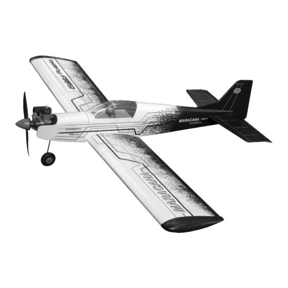
MARACANA
MARACANA
.40 ARF LOW WING TRAINER
EP
You can use both
Gas or Electric power
Wingspan:
Fuselage length: 48in.(1220mm)
Engine:
40 - 46 2T / 48 - 52 4T
Electric Motor:
Radio:
5 channel / 5 servo
RC Functions: Rudder - Elevator - Aileron - Throttle
WARNING! This radio controlled model is NOT a toy. If modified or flown carelessly it could go out of control and
cause serious human injury or property damage. Before flying your airplane, ensure the air field is spacious enough.
Always fly it outdoors in safe areas and seek professional advice if you are unexperienced.
WARNING! Please do not clean your model with pure alcohol, only use liquid soap with water or use glass cleaner to
clean on surface of your model to keep the colour not fade.
RADIO CONTROL MODEL
ASSEMBLY INSTRUCTION
VQA085
GP
59in.(1520mm)
600W
Every body can fly
Advertisement
Table of Contents

Related Manuals for VQ Model MARACANA VQA085


Summary of Contents for VQ Model MARACANA VQA085
- Page 1 RADIO CONTROL MODEL ASSEMBLY INSTRUCTION MARACANA MARACANA .40 ARF LOW WING TRAINER Every body can fly VQA085 You can use both Gas or Electric power Wingspan: 59in.(1520mm) Fuselage length: 48in.(1220mm) Engine: 40 - 46 2T / 48 - 52 4T Electric Motor: 600W Radio:...
-
Page 2: Required For Operation
REQUIRED FOR OPERATION Purchase separetely Silicone tube 10.5x6 for .40 - 2 cycle engine 11x6 for .46 - 2 cycle engine 11x7 for .52 - 4 cycle engine 12x7 ~13x6 - Electric motor Extension for aileron servo. Brushless Motor Radio a 5 channel (min) .40 - .46 - 2T .48 - .52 4T 600-720W... - Page 3 1-Aileron extension cord installation WING BOTTOM-VIEW 30cm Extension cord Using the thread (pre-installed at factory) to slide the aileron extension cord into the wing half. Thread (pre-installed at factory) Using the adhesive tape to secure the one WING BOTTOM-VIEW end of the aileron extension cord in place. Adhesive tape Using the adhesive tape to secure the one end of the aileron extension cord in place.
-
Page 4: Joining The Wing
2- Joining the wing Before gluing: - Draw the center line on the wing joiner. - Trial fit each part before gluing . Be certain that there are no gaps. If the parts will join, but with a gaps, sand or trim the parts a little at a time until the parts meet exactly with no gaps. -
Page 5: Aileron Servo Installation
3-Aileron servo installation -Switch on the radio (trims centered) then mount the ailerons servo horn in neutral position. -The servo horn should be Included with the radio set. perpendicular to the servo 1-Cut away the covering of the wing bottom where the aileron servo goes. -
Page 6: Installing The Main Gear
5- Installing the main gear Main gear Nylon strap...4 3x12 mm screw BOTTOM VIEW 3x12mm screw...8 4mm collar...2 1- Locate the main landing gear struts and place them into the landing gear slot as show. Make sure that the ends of the struts are inserted into the holes in the landing gear channel. -
Page 7: Front Landing Gear
7- Rudder and elevator Note: The slots for the control horn installation are pre- cut at factory. Trial fit the hon. Actuate elevator Thin CA linkage manually it should not be hard spot. Adjust if necessary. Insert the plate through the foot of the horn. - Page 8 10- Engine installation FUSELAGE BOTTOM VIEW Pull here to open Throttle servo Magnetic tank hatch. Throttle linkage Install the engine 1-Attach with the delivered screws the engine mount in place. 2-Install the engine. 3-Install throttle servo inside the fuselage. 4-Slide the throttle linkage in its outer tube from the front of the fuselage and insert the “Z”...
Need help?
Do you have a question about the MARACANA VQA085 and is the answer not in the manual?
Questions and answers