Vega VEGABAR 52 Operating Instructions Manual
4...20 ma/hart
Hide thumbs
Also See for VEGABAR 52:
- Product information (32 pages) ,
- Operating instructions manual (64 pages)

Subscribe to Our Youtube Channel
Related Manuals for Vega VEGABAR 52


Summary of Contents for Vega VEGABAR 52
-
Page 1: Operating Instructions
Operating Instructions VEGABAR 52 4 … 20 mA/HART Document ID: 36717 Process pressure... -
Page 2: Table Of Contents
Setup steps ....... 32 Menu schematic ......42 VEGABAR 52 • 4 … 20 mA/HART... - Page 3 10.2 Dimensions ....... 65 Supplementary documentation Information: Supplementary documents appropriate to the ordered version come with the delivery. You can find them listed in chapter "Product description". Editing status: 2012-03-09 VEGABAR 52 • 4 … 20 mA/HART...
-
Page 4: About This Document
This symbol indicates special instructions for Ex applications. List The dot set in front indicates a list with no implied sequence. à Action This arrow indicates a single action. Sequence Numbers set in front indicate successive steps in a procedure. VEGABAR 52 • 4 … 20 mA/HART... -
Page 5: For Your Safety
During work on and with the device the required personal protective equipment must always be worn. 2.2 Appropriate use VEGABAR 52 is a pressure transmitter for measurement of gauge pressure, absolute pressure and vacuum. You can find detailed information on the application range in chapter "Product description". -
Page 6: Safety Label On The Instrument
2.6 CE conformity This device fulfills the legal requirements of the applicable EC guidelines. By attaching the CE mark, VEGA provides a confirmation of successful testing. You can find the CE conformity declaration in the download area of "www.vega.com". -
Page 7: Product Description
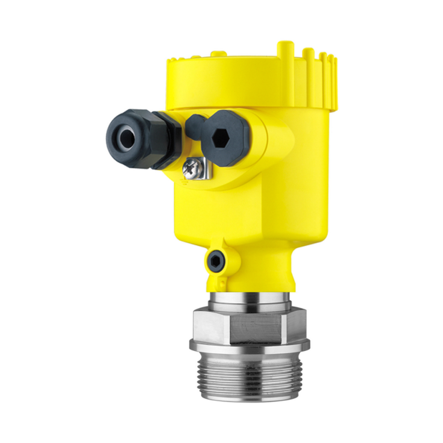
Housing cover, optionally available with indicating and adjustment module The components are available in different versions. Fig. 1: Example of a VEGABAR 52 with manometer connection G½ A according to EN 837 and plastic housing Housing cover with integrated indicating and adjustment module (optional) Housing with electronics Process fitting with measuring cell... -
Page 8: Principle Of Operation
Software from 3.82 3.2 Principle of operation VEGABAR 52 is a pressure transmitter for use in the paper, food Application area processing and pharmaceutical industries as well as in water/sewage water plants. Depending on the version, it is used for level, gauge, absolute pressure or vacuum measurement. -
Page 9: Operation
The instrument can be adjusted with the following adjustment media: With indicating and adjustment module with the suitable VEGA DTM in conjunction with an adjustment software according to the FDT/DTM standard, e.g. PACTware and with manufacturer-specific adjustment programs AMS™ or PDM With a HART handheld 3.4 Packaging, transport and storage... -
Page 10: Accessories And Replacement Parts
It is connected to the sensor with an up adjustment unit to 25 m long, four-wire, screened standard cable. You can find further information in the operating instructions "VEGADIS 61" (Document-ID 27720). VEGABAR 52 • 4 … 20 mA/HART... - Page 11 The electronics module is a replacement part for pressure transmitter Electronics module VEGABAR. One version is available for each type of signal output. You find further information in the operating instructions "Electronics module VEGABAR series 50 and 60 " (Document-ID 30175). VEGABAR 52 • 4 … 20 mA/HART...
-
Page 12: Mounting
The ventilation of the electronics housing as well as the atmospheric Ventilation and pressure pressure compensation for the measuring cell are realised via a filter compensation element in the area of the cable gland. VEGABAR 52 • 4 … 20 mA/HART... - Page 13 Higher process temperatures often mean also higher ambient Temperature limits temperatures. Make sure that the upper temperature limits stated in chapter "Technical data" for the environment of the electronics housing and connection cable are not exceeded. VEGABAR 52 • 4 … 20 mA/HART...
-
Page 14: Mounting Steps
Fig. 5: Temperature ranges Process temperature Ambient temperature 4.2 Mounting steps For mounting VEGABAR 52, a welded socket is required. You can find Welding the socket these components in the supplementary instructions manual "Welded socket and seals". Seal the thread with teflon, hemp or a similar resistant seal material on Sealing/Screwing in the process fitting thread 1½... - Page 15 180° to the wall mounting plate. Warning: The four screws of the socket housing must only be hand screwed. A torque > 5 Nm (3.688 lbf ft) can damage the wall mounting plate. VEGABAR 52 • 4 … 20 mA/HART...
-
Page 16: Connecting To Power Supply
The data for power supply are specified in chapter "Technical data". Provide a reliable separation between the supply circuit and the mains circuits according to DIN VDE 0106 part 101. The VEGA power supply units VEGATRENN 149A Ex, VEGASTAB 690 as well as all VEGAMETs and VEGASCANs meet this requirement. -
Page 17: Connection Procedure
flow over the cable screen. In case of grounding on both sides this can be achieved by the use of a capacitor or a separate potential equalisation. 5.2 Connection procedure Proceed as follows: Single/Double chamber housing Unscrew the housing cover VEGABAR 52 • 4 … 20 mA/HART... - Page 18 The electrical connection is finished. Fig. 7: Connection steps 6 and 7 Proceed as follows: IP 68 version with exter- nal housing Loosen the four screws on the housing base with an Allen key size VEGABAR 52 • 4 … 20 mA/HART...
- Page 19 5 cm of the cable mantle, strip approx. 1 cm insulation from the ends of the individual wires. After shortening the cable, fasten the type plate with sup- port back onto the cable. VEGABAR 52 • 4 … 20 mA/HART...
-
Page 20: Wiring Plan, Single Chamber Housing
Spring-loaded terminals for connection of the external indication VEGADIS Ground terminal for connection of the cable screen Spring-loaded terminals for voltage supply Wiring plan Display I 2 C Fig. 10: Wiring plan, single chamber housing Voltage supply, signal output VEGABAR 52 • 4 … 20 mA/HART... -
Page 21: Wiring Plan, Double Chamber Housing
Display I 2 C 5 6 7 8 Fig. 11: Electronics compartment, double chamber housing Plug connector for VEGACONNECT (I²C interface) Internal connection cable to the connection compartment Terminals for VEGADIS 61 VEGABAR 52 • 4 … 20 mA/HART... - Page 22 Spring-loaded terminals for voltage supply Plug connector for VEGACONNECT (I²C interface) Ground terminal for connection of the cable screen Wiring plan I 2 C Fig. 13: Wiring plan, double chamber housing Voltage supply, signal output VEGABAR 52 • 4 … 20 mA/HART...
-
Page 23: Wiring Plan, Double Chamber Housing Ex D
Internal connection cable to the connection compartment Terminals for VEGADIS 61 Connection compart- ment Fig. 15: Connection compartment, Ex-d double chamber housing Spring-loaded terminals for power supply and cable screen Ground terminal for connection of the cable screen VEGABAR 52 • 4 … 20 mA/HART... -
Page 24: Wiring Plan - Version Ip 66/Ip 68 (1 Bar)
5.6 Wiring plan - version IP 66/IP 68 (1 bar) Wire assignment con- nection cable Fig. 17: Wire assignment connection cable brown (+) and blue (-) to power supply or to the processing system Shielding VEGABAR 52 • 4 … 20 mA/HART... -
Page 25: Wiring Plan, External Housing With Version Ip
5 Connecting to power supply 5.7 Wiring plan, external housing with version IP 68 (25 bar) Overview Fig. 18: VEGABAR 52 in IP 68 version 25 bar and axial cable outlet, external housing VEGABAR 52 • 4 … 20 mA/HART... - Page 26 Spring-loaded terminals for voltage supply Ground terminal for connection of the cable screen Cable gland to the process component Spring-loaded terminals for connection of the external indication VEGADIS Plug connector for VEGACONNECT (I²C interface) VEGABAR 52 • 4 … 20 mA/HART...
-
Page 27: Switch-On Phase
I 2 C Fig. 21: Wiring plan external electronics Voltage supply 5.8 Switch-on phase After connecting VEGABAR 52 to power supply or after a voltage Switch-on phase recurrence, the instrument carries out a self-check for approx. 30 seconds: VEGABAR 52 • 4 … 20 mA/HART... - Page 28 Output signal jumps briefly (approx. 10 seconds) to the set fault current Then the corresponding current is outputted to the cable (the value corresponds to the actual level as well as the settings already carried out, e.g. factory setting). VEGABAR 52 • 4 … 20 mA/HART...
-
Page 29: Set Up With The Indicating And Adjustment Module Plicscom
Screw housing cover with inspection window tightly back on Removal is carried out in reverse order. The indicating and adjustment module is powered by the sensor, an additional connection is not necessary. VEGABAR 52 • 4 … 20 mA/HART... - Page 30 Fig. 22: Insert indicating and adjustment module Note: If you intend to retrofit the instrument with an indicating and adjustment module for continuous measured value indication, a higher cover with an inspection glass is required. VEGABAR 52 • 4 … 20 mA/HART...
-
Page 31: Adjustment System
The functions of the individual keys are shown in the above illustration. Approx. 10 minutes after the last pressing of a key, an automatic reset to measured value indication is triggered. Any values not confirmed with [OK] will not be saved. VEGABAR 52 • 4 … 20 mA/HART... -
Page 32: Setup Steps
DTM. HART mode Standard Address 0 VEGABAR 52 can be used for level as well as for process pressure Level or process press- measurement. Default setting is level measurement. The mode can be ure measurement changed in the adjustment menu. - Page 33 Unit of measurement Density unit kg/dm³ ▶ Select the requested unit, e.g. kg/dm³ with [->] and confirm with [OK], the submenu "Density" appears. Selection options: mbar, bar, psi, Pa, kPa, MPa, inHg, mmHg, inH VEGABAR 52 • 4 … 20 mA/HART...
- Page 34 0000.0 mbar Set the requested percentage value with [+] and [->]. Confirm with [OK] and edit the requested mbar value. Set the requested mbar value with [+] and [->]. Selection options: °C, °F. VEGABAR 52 • 4 … 20 mA/HART...
- Page 35 The editing procedure can be aborted with [ESC] or the displayed limit value can be accepted with [OK]. Process pressure measurement Set up VEGABAR 52 in the following sequence: Parameter ad- justment "Pro- Select application "Process pressure measurement"...
- Page 36 The actual measured value is displayed in addition to the menu items for zero/span adjustment. VEGABAR 52 is preset to application "Level measurement". Proceed Select application "Pro- as follows when switching over to application "Process pressure cess pressure measure- measurement":...
- Page 37 53 mbar Select with [->], e.g. to accept actual measured value. Position correction Accept current measured value? ▶ Accept Edit Confirm with [OK] and move to min.(zero) adjustment with [->]. Selection options: °C, °F. VEGABAR 52 • 4 … 20 mA/HART...
- Page 38 If the adjustment ranges are exceeded, the message "Outside parameter limits" appears. The editing procedure can be aborted with [ESC] or the displayed limit value can be accepted with [OK]. VEGABAR 52 • 4 … 20 mA/HART...
- Page 39 [->] key. Caution: Note the following if the VEGABAR 52 with corresponding approval is used as part of an overfill protection system according to WHG: If a linearisation curve is selected, the measuring signal is no longer compulsorily linear proportional to the level.
- Page 40 Temperature unit No reset Position correction No reset No reset Display Lighting No reset Service No reset Language HART mode No reset No reset Application With instruments with signal output 4 … 20 mA/HART VEGABAR 52 • 4 … 20 mA/HART...
- Page 41 You will find a detailed description of these menu items in the operating instructions manual "Indicating and adjustment module". Special parameters are parameters which are set customer-specifically on the service level with the adjustment software PACTware. VEGABAR 52 • 4 … 20 mA/HART...
-
Page 42: Menu Schematic
Basic adjustment ▶ Display Diagnostics Service Info Displayed value Displayed value Display unit ▼ Scaling 0 % = 0.0 ▼ ▼ Pressure Scaled Volume ▼ 100 % = 100.0 Lighting ▼ Switched off VEGABAR 52 • 4 … 20 mA/HART... - Page 43 Copy sensor data? Enable? Address 0 Application ▼ Level Info Basic adjustment Display Diagnostics Service ▶ Info Instrument type Calibration date Last change using PC Sensor characteristics Software version Display now? Serial number VEGABAR 52 • 4 … 20 mA/HART...
-
Page 44: Set Up With Pactware And Other Adjustment Programs
USB cable to the PC VEGACONNECT Sensor VEGACONNECT exter- nally TWIST Fig. 25: Connection via VEGACONNECT externally I²C bus (com.) interface on the sensor I²C connection cable of VEGACONNECT VEGACONNECT USB cable to the PC VEGABAR 52 • 4 … 20 mA/HART... -
Page 45: Parameter Adjustment With Pactware
A detailed description is available in the online help of PACTware and the VEGA DTMs. Note: Keep in mind that for setup of VEGABAR 52, DTM-Collection in the actual version must be used. VEGABAR 52 • 4 … 20 mA/HART... -
Page 46: Parameter Adjustment With Ams™ And Pdm
7 Set up with PACTware and other adjustment programs All currently available VEGA DTMs are included as a DTM Collection on a CD. They can be purchased for a token fee from the responsible VEGA agency. In addition, the actual PACTware version is also available on this CD. -
Page 47: Maintenance And Fault Rectification
Should these measures not be successful, please call in urgent cases 24 hour service hotline the VEGA service hotline under the phone no. +49 1805 858550. The hotline is available to you 7 days a week round-the-clock. Since we offer this service world-wide, the support is only available in the English language. - Page 48 Depending on the reason for the fault and the measures taken, the Reaction after fault rec- steps described in chapter "Set up" may have to be carried out again. tification Fault message can also appear if the pressure is higher than the nominal range. VEGABAR 52 • 4 … 20 mA/HART...
-
Page 49: Calculation Of Total Deviation (According To Din 16086)
Pressure measurement in the pipeline 8 bar (800 KPa) Example Product temperature 50 °C, hence within the compensated range VEGABAR 52 with measuring range 10 bar Calculation of the set Turn Down: TD = 10 bar/8 bar, TD = 1.25 Basic accuracy digital output signal in percent: = √((F... -
Page 50: Exchanging The Electronics Module
These are not included in the electronics module without serial number. The serial number is stated on the type label of VEGABAR 52 or on the delivery note. 8.5 Software update... -
Page 51: Instrument Repair
Prepare update provide the connection from the PC to the instrument via the interface adapter. Start PACTware and go via the menu "Project" to the VEGA project assistant. Select "USB" and "Set instruments online". Activate the project assistant with "Start". The assistant establishes the connection automatically and opens the parameter adjustment window "Sensor # online parameter adjustment". -
Page 52: Dismounting
Correct disposal avoids negative effects on humans and the environ- ment and ensures recycling of useful raw materials. Materials: see chapter "Technical data" If you have no way to dispose of the old instrument properly, please contact us concerning return and disposal. VEGABAR 52 • 4 … 20 mA/HART... -
Page 53: Supplement
IP 68 version Type label support on connection cable PE hard Connection cable with IP 68 1 bar version Weight approx. 0.8 … 8 kg (1.764 … 17.64 lbs), depending on process fitting VEGABAR 52 • 4 … 20 mA/HART... - Page 54 -50 … +150 °C (-58 … +302 °F) Range 1 °C (1.8 °F) Resolution Depending on the respective instrument and the process fitting, the tem- perature can deviate from the real process temperature. VEGABAR 52 • 4 … 20 mA/HART...
- Page 55 -1 … +60 bar/-100 … +6000 kPa +200 bar/+20000 kPa -1 bar/-100 kPa -0.05 … +0.05 bar/-5 … +5 kPa +15 bar/+1500 kPa -0.2 bar/-20 kPa Values less than -1 bar cannot be set. VEGABAR 52 • 4 … 20 mA/HART...
- Page 56 -0.725 … +0.725 psig +217.6 psig -2.901 psig -1.450 … +1.450 psig +290.1 psig -5.801 psig -2.901 … +2.901 psig +435.1 psig -11.60 psig -7.252 … +7.252 psig +507.6 psig -14.50 psig/-100 kPa Absolute pressure VEGABAR 52 • 4 … 20 mA/HART...
- Page 57 Turn down 1 : 1 up to 5 : 1 < 0.2 % Turn down > 5 : 1 < 0.04 % x TD Deviation with absolute pressure measuring range 0.1 bar Incl. non-linearity, hysteresis and non-repeatability. VEGABAR 52 • 4 … 20 mA/HART...
- Page 58 Applies to digital HART interface as well as to analogue current output 4 … 20 mA under reference conditions. Specifications refer to the set span. Turn down (TD) is the relation nominal measuring range/set span. Long-term drift of the zero signal: VEGABAR 52 • 4 … 20 mA/HART...
- Page 59 1 h: 140 °C/284 °F clea- ning temperature EPDM (ET 7056) -40 … +120 °C (-40 … +248 °F) 1 h: 140 °C/284 °F clea- ning temperature With process fitting PVDF, max. 100 °C (212 °F). VEGABAR 52 • 4 … 20 mA/HART...
- Page 60 (optional) Tested according to the guidelines of German Lloyd, GL directive 2. Tested according to EN 60068-2-27. Depending on the version M12 x 1, according to ISO 4400, Harting, 7/8" FF. VEGABAR 52 • 4 … 20 mA/HART...
- Page 61 1 x blind stopper M20 x 1.5 1 x plug (depending on the version), 1 x blind stopper M20 x 1.5 Depending on the version M12 x 1, according to ISO 4400, Harting, 7/8" FF. VEGABAR 52 • 4 … 20 mA/HART...
- Page 62 20 … 30 V DC Ex d instrument 20 … 36 V DC Permissible residual ripple < 100 Hz < 1 V 100 Hz … 10 kHz < 10 mV see diagram Load VEGABAR 52 • 4 … 20 mA/HART...
- Page 63 Instruments with gauge pressure measuring ranges cannot detect the am- bient pressure when submerged, e.g. in water. This can lead to falsification of the measured value. Only with instruments with absolute pressure ranges. VEGABAR 52 • 4 … 20 mA/HART...
- Page 64 Instruments with approvals can have different technical data depending on the version. That's why the associated approval documents have to be noted with these instruments. They are part of the delivery or can be downloaded under www.vega.com via "VEGA Tools" and "serial number search" as well as via "Downloads" and "Approvals".
-
Page 65: Dimensions
½ NPT Fig. 31: Housing versions in protection IP 66/IP 68 (0.2 bar) - with integrated indicating and adjustment module the housing is 9 mm/0.35 in higher Single chamber version Double chamber version VEGABAR 52 • 4 … 20 mA/HART... - Page 66 Fig. 33: Housing versions in protection IP 66/IP 68 (0.2 bar) - with integrated indicating and adjustment module the housing is 9 mm/0.35 in higher Single chamber version, electropolished Single chamber version, precision casting Double chamber version, precision casting VEGABAR 52 • 4 … 20 mA/HART...
- Page 67 42mm ") 40mm ") 90 mm (3 ") 110 mm (4 ") ~ 66 mm (2 ") Fig. 35: IP 68 version with external housing - non-Ex Lateral cable outlet Axial cable outlet VEGABAR 52 • 4 … 20 mA/HART...
- Page 68 GM/GN Fig. 36: VEGABAR 52 - threaded fitting: GV/GC = G½ A manometer connection EN 837, GL/GU = G½ A inner G¼ A, GS = G½ A inner G¼ A PVDF, GI = G½ A manometer connection volume-reduced, GM/GN = ½ NPT, GB = M20 x 1.5 manometer connection EN 837...
- Page 69 (2.17") (2.68") Fig. 37: VEGABAR 52 - threaded fitting: GG = G1½ A, GW = G1½ A PVDF, GN = 1½ NPT, GE = G2 A For the version with temperature range up to 150 °C/302 °F, the measure of length increases by 28 mm (1.1 in).
- Page 70 ø 105 mm ") Fig. 38: VEGABAR 52 - hygienic fitting: CD/CC = Clamp 1"/Clamp 1½" acc. to DIN 32676, ISO 2852/316L, CA = Clamp 2", CA = Clamp 2½", LA = hygienic fitting with compression nut F40, AA = DRD...
- Page 71 RS/RT Fig. 39: VEGABAR 52 - hygienic fitting: TA = Tuchenhagen Varivent DN 32, TB = Tuchenhagen Varivent DN 25, RA/RB = bolting DN 40/DN 50 according to DIN 11851, RD = bolting DN 50 according to DIN 11864, RS/RT = SMS DN 38/DN 51 VEGABAR 52 •...
- Page 72 " " " " 3” 150 lbs 12xø 15” " " " " " Fig. 40: VEGABAR 52 - flange connection Flange connection according to DIN 2501 Flange fitting according to ANSI B16.5 VEGABAR 52 • 4 … 20 mA/HART...
- Page 73 ø 40 mm (1.58") Fig. 41: VEGABAR 52 - threaded fitting for the paper industry: BA/BB = M44 x 1.25, BE = M56 x 1.25, DG = M48 x 1.25 with extension D 40 mm VEGABAR 52 • 4 … 20 mA/HART...
- Page 74 (1.89...3.54") Fig. 42: VEGABAR 52 - flange connection for the paper industry: TR = flange DN 50 with selectable tube, TS = flange DN 80 with selectable tube, FG = flange tube for ball valve fitting, EW = flange for manometer lug...
- Page 75 (1.89") 50 mm 50 mm (1.97") (1.97") Fig. 43: VEGABAR 52 - flange connection for the paper industry: FT = absolutely front-flush for headbox, EV = absolutely front-flush for headbox (flange 2-times flattened) VEGABAR 52 • 4 … 20 mA/HART...
- Page 76 Les lignes de produits VEGA sont globalement protégées par des droits de propriété intellectuelle. Pour plus d'informations, on pourra se référer au site http://www.vega. VEGA lineas de productos están protegidas por los derechos en el campo de la propiedad industrial. Para mayor información revise la pagina web http://www.vega.com Линии...
- Page 77 - Double chamber housing 22 HART multidrop 32 - External electronics 27 Hotline 47 - Single chamber housing 20 Linearisation curve 39 Zero adjustment 38 Maintenance 47 Max. adjustment 35 Min. adjustment 34 VEGABAR 52 • 4 … 20 mA/HART...
- Page 78 Index VEGABAR 52 • 4 … 20 mA/HART...
- Page 79 Index VEGABAR 52 • 4 … 20 mA/HART...
- Page 80 All statements concerning scope of delivery, application, practical use and operating conditions of the sensors and processing systems correspond to the information avail- able at the time of printing. © VEGA Grieshaber KG, Schiltach/Germany 2012 Subject to change without prior notice 36717-EN-120324...
Need help?
Do you have a question about the VEGABAR 52 and is the answer not in the manual?
Questions and answers