Vega VEGABAR 82 Operating Instructions Manual
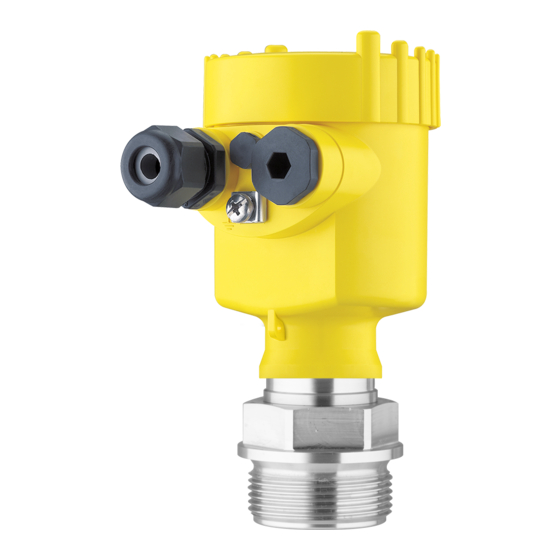
Pressure transmitter with ceramic measuring cell
Hide thumbs
Also See for VEGABAR 82:
- Operating instructions manual (104 pages) ,
- Quick setup manual (24 pages) ,
- Product information (16 pages)

Related Manuals for Vega VEGABAR 82


Summary of Contents for Vega VEGABAR 82
- Page 1 Operating Instructions Pressure transmitter with ceramic measuring cell VEGABAR 82 Profibus PA Document ID: 45031...
-
Page 2: Table Of Contents
Parameter adjustment - Quick setup ................34 Parameter adjustment - Extended adjustment..............34 Menu overview ....................... 46 Save parameter adjustment data..................48 Setup with PACTware ......................49 Connect the PC ......................49 Parameterization ......................49 VEGABAR 82 • Profibus PA... - Page 3 Safety instructions for Ex areas: Take note of the Ex specific safety instructions for Ex applications. These instructions are attached as documents to each instrument with Ex approval and are part of the operating instructions. Editing status: 2022-04-20 VEGABAR 82 • Profibus PA...
-
Page 4: About This Document
Symbols used Document ID This symbol on the front page of this instruction refers to the Docu- ment ID. By entering the Document ID on www.vega.com you will reach the document download. Information, note, tip: This symbol indicates helpful additional infor- mation and tips for successful work. -
Page 5: For Your Safety
During work on and with the device, the required personal protective equipment must always be worn. Appropriate use The VEGABAR 82 is a pressure transmitter for process pressure and hydrostatic level measurement. You can find detailed information about the area of application in chapter "... -
Page 6: Namur Recommendations
The environment management system is certified according to DIN EN ISO 14001. Please help us fulfil this obligation by observing the environmental instructions in this manual: • Chapter " Packaging, transport and storage" • Chapter " Disposal" VEGABAR 82 • Profibus PA... -
Page 7: Product Description
" Dimensions") The further scope of delivery encompasses: • Documentation – Quick setup guide VEGABAR 82 – Test certificate for pressure transmitters – Instructions for optional instrument features – Ex-specific " Safety instructions" (with Ex versions) – If necessary, further certificates... -
Page 8: Principle Of Operation
Alternatively, you can access the data via your smartphone: • Download the VEGA Tools app from the " Apple App Store" or the " Google Play Store" • Scan the QR-code on the type label of the device or •... - Page 9 3 Product description Fig. 2: Process pressure measurement VEGABAR 82 Electronic differential Depending on the version, the VEGABAR 82 is also suitable for pressure electronic differential pressure measurement. For this, the instrument is combined with a Secondary sensor. Fig. 3: Electronic differential pressure measurement via a Primary/Secondary...
- Page 10 It thus has no influence on the measured value. Seal concepts The following presentations show examples for the installation of the ceramic measuring cell into the process fitting and the different seal concepts. VEGABAR 82 • Profibus PA...
- Page 11 Process fitting Diaphragm Completely front-flush The completely front-flush mounting is particularly suitable for ap- mounting with single seal plications in the paper industry. The diaphragm is in the pulp flow, is hence cleaned and protected against buildup. VEGABAR 82 • Profibus PA...
- Page 12 The form seal of the measuring cell protects also the glass joint. Fig. 9: Hygienic installation of the measuring cell (example: hygienic fitting with compression nut) Measuring cell Form seal for the measuring cell Gap-free seal for process fitting Process fitting Diaphragm VEGABAR 82 • Profibus PA...
-
Page 13: Supplementary Cleaning Procedures
Diaphragm Hole for leakage detection Supplementary cleaning procedures The VEGABAR 82 is also available in the version " Oil, grease and silicone-free" or cleaning for paint compatible version (LABS). These instruments have passed through a special cleaning procedure to remove oil, grease and paint-wetting impairment substances (PWIS). -
Page 14: Accessories
Secondary sensors Secondary sensors of VEGABAR series 80 enable in conjunction with VEGABAR 82 an electronic differential pressure measurement. VEGADIS 81 The VEGADIS 81 is an external display and adjustment unit for VEGA plics sensors. ® The VEGADIS adapter is an accessory part for sensors with double VEGADIS adapter chamber housings. - Page 15 3 Product description Welded sockets are used to connect the devices to the process. Welded socket, threaded and hygienic adapter Threaded and hygienic adapters enable simple adaptation of devices with standard threaded fittings to process-side hygiene connections. VEGABAR 82 • Profibus PA...
-
Page 16: Mounting
Vibrations Avoid damages on the device by lateral forces, for example by vibra- tions. It is thus recommended to fix the devices with process fitting VEGABAR 82 • Profibus PA... -
Page 17: Instructions For Oxygen Applications
Fig. 11: Temperature ranges Process temperature Ambient temperature Instructions for oxygen applications Oxygen applications Oxygen and other gases can be explosive when brought into contact with oils, grease and plastics, so the following measures must also be taken: VEGABAR 82 • Profibus PA... -
Page 18: Ventilation And Pressure Compensation
Instruments with absolute pressure → Filter element - Position Turn the metal ring in such a way that the filter element points Ex-d version downward after installation of the instrument. This provides better protection against buildup. VEGABAR 82 • Profibus PA... - Page 19 With relative pressure measuring ranges, the ambient pressure is detected and compensated by a reference sensor in the electronics. Fig. 14: Position of the filter element - gastight leadthrough Filter element Gas-tight leadthrough VEGABAR 82 • Profibus PA...
-
Page 20: Process Pressure Measurement
Pipeline Keep the following in mind when setting up the measuring system: Measurement setup in vapours • Connect via a siphon • Do not insulate the siphon • Fill the siphon with water before setup VEGABAR 82 • Profibus PA... - Page 21 The effective pressure line is always filled with liquid and gas bubbles can bubble up to the process line. Fig. 18: Measurement setup for the process pressure measurement of liquids in pipelines VEGABAR 82 Blocking valve Pipeline VEGABAR 82 • Profibus PA...
-
Page 22: Level Measurement
Fig. 19: Measurement setup for the level measurement External housing Configuration Fig. 20: Configuration, process module, external housing Pipeline Process module Connection cable process assembly - External housing External housing Signal cable VEGABAR 82 • Profibus PA... -
Page 23: Connecting To The Bus System
In the case of instrument housings with metric thread, the cable glands are screwed in at the factory. They are sealed with plastic plugs as transport protection. Note: You have to remove these plugs before electrical connection. VEGABAR 82 • Profibus PA... -
Page 24: Connecting
5. Insert the cable into the sensor through the cable entry Fig. 21: Connection steps 5 and 6 Single chamber housing Double chamber housing 6. Insert the wire ends into the terminals according to the wiring plan VEGABAR 82 • Profibus PA... -
Page 25: Single Chamber Housing
Selection switch for instrument address For external display and adjustment unit Ground terminal for connection of the cable screening Double chamber housing The following illustrations apply to the non-Ex as well as to the Ex-ia version. VEGABAR 82 • Profibus PA... - Page 26 6 7 8 Fig. 24: Connection compartment - double chamber housing Voltage supply, signal output For display and adjustment module or interface adapter For external display and adjustment unit Ground terminal for connection of the cable screening VEGABAR 82 • Profibus PA...
-
Page 27: Double Chamber Housing With Vegadis-Adapter
Fig. 26: Top view of the M12 x 1 plug connector Pin 1 Pin 2 Pin 3 Pin 4 Contact pin Colour, connection ca- Terminal, electronics ble in the sensor module Pin 1 Brown Pin 2 White Pin 3 Blue Pin 4 Black VEGABAR 82 • Profibus PA... -
Page 28: Housing Ip66/Ip68 (1 Bar)
Blue (-): to voltage supply or to the processing system Shielding Breather capillaries with filter element External housing with version IP68 (25 bar) Overview Fig. 28: VEGABAR 82 in IP68 version 25 bar with axial cable outlet, external housing Transmitter Connection cable External housing... - Page 29 Cable gland for voltage supply Cable gland for connection cable, transmitter Terminal compartment, housing socket 1 2 3 4 Fig. 30: Connection of the process component in the housing base Yellow White Black Shielding Breather capillaries VEGABAR 82 • Profibus PA...
-
Page 30: Switch-On Phase
Indication of a status message on the display or PC Then the actual measured value is output to the signal cable. The value takes into account settings that have already been carried out, e.g. default setting. VEGABAR 82 • Profibus PA... -
Page 31: Set Up With The Display And Adjustment Module
The display and adjustment module is powered by the sensor, an ad- ditional connection is not necessary. Fig. 32: Installing the display and adjustment module in the electronics compart- ment of the single chamber housing VEGABAR 82 • Profibus PA... -
Page 32: Adjustment System
– Move to the menu overview – Confirm selected menu – Edit parameter – Save value • [->] key: – Change measured value presentation – Select list entry – Select menu items – Select editing position • [+] key: VEGABAR 82 • Profibus PA... -
Page 33: Measured Value Indication
With the [->] key you can move between three different indication tion modes. In the first view, the selected measured value is displayed in large digits. In the second view, the selected measured value and a respective bargraph presentation are displayed. VEGABAR 82 • Profibus PA... -
Page 34: Parameter Adjustment - Quick Setup
You can find a description of the individual steps in the quick setup guide of the sensor. You can find " Extended adjustment" in the next sub-chapter. Parameter adjustment - Extended adjustment For technically demanding measuring points, you can carry out extended settings in " Extended adjustment". VEGABAR 82 • Profibus PA... - Page 35 Hardware addressing is effective if an address less than 126 is set with the address selection switches on the electronics module of VEGABAR 82. In such case, software addressing has no effect - only the set hardware address applies. Software addressing Software addressing is only effective if address 126 or higher is set on the instrument with the address selection switches.
- Page 36 In this menu item you activate/deactivate the Secondary sensor for electronic differential pressure and select the application. VEGABAR 82 can be used for process pressure and level measure- ment. Default setting is process pressure measurement. The mode can be changed in this adjustment menu.
- Page 37 Adjustment VEGABAR 82 always measures pressure independently of the pro- cess variable selected in the menu item " Application". To output the selected process variable correctly, an allocation of the output signal to 0 % and 100 % must be carried out (adjustment).
- Page 38 Now select with [->] the menu item " Zero adjustment" and con- firm with [OK]. 2. Edit the mbar value with [OK] and set the cursor to the requested position with [->]. 3. Set the requested mbar value with [+] and store with [OK]. VEGABAR 82 • Profibus PA...
- Page 39 3. Set the requested percentage value (e.g. 10 %) with [+] and save with [OK]. The cursor jumps now to the pressure value. 4. Enter the pressure value corresponding to the min. level (e.g. 0 mbar). VEGABAR 82 • Profibus PA...
- Page 40 This must be considered by the user especially when setting the switching point on the limit signal transmitter. AI FB1 Since the parameter adjustment of the Function Block 1 (FB1) is very comprehensive, it was divided into various submenu items. VEGABAR 82 • Profibus PA...
- Page 41 0 … 999 s in this menu item. The increment is 0.1 s. The default setting is a damping of 0 s. Lock/Unlock adjustment In the menu item " Lock/unlock adjustment" you safeguard the sensor parameters against unauthorized or unintentional modifications. VEGABAR 82 • Profibus PA...
- Page 42 Czech • Turkish In delivery status, the VEGABAR 82 is set to English. Display value 1 and 2 In this menu item, you define which measured value is displayed. The default setting for the display value is " Lin. percent".
- Page 43 In another window you can carry out a reset of the two peak values separately. Simulation In this menu item you simulate measured values. Hence, the signal path can be tested via the bus system to the input card of the control system. VEGABAR 82 • Profibus PA...
- Page 44 Any pro- grammed linearisation curve as well as the measured value memory are deleted. Note: You can find the default values of the device in chapter " Menu over- view". VEGABAR 82 • Profibus PA...
- Page 45 6.5.5 Info Device name In this menu item, you can read out the instrument name and the instrument serial number: Instrument version In this menu item, the hardware and software version of the sensor is displayed. VEGABAR 82 • Profibus PA...
-
Page 46: Menu Overview
Adjustment unit (m, bar, Pa, psi … user- mbar (with nominal measuring range defined) ≤ 400 mbar) bar (with nominal measuring ranges ≥ 1 bar) Temperature unit (°C, °F) °C Parameter only active if the instrument is connected to the Secondary sensor VEGABAR 82 • Profibus PA... - Page 47 Process pressure linearized percent, measuring cell tem- perature, electronics temperature Additional adjustments Menu item Parameter Default value Date/Time Actual date/Actual time Reset Delivery status, basic settings Copy instrument settings Read from sensor, write into sensor VEGABAR 82 • Profibus PA...
-
Page 48: Save Parameter Adjustment Data
If the instrument is equipped with a display and adjustment module, In the display and adjust- ment module the parameter adjustment data can be saved therein. The procedure is described in menu item " Copy device settings". VEGABAR 82 • Profibus PA... -
Page 49: Setup With Pactware
Further setup steps are described in the operating instructions manu- al " DTM Collection/PACTware" attached to each DTM Collection and which can also be downloaded from the Internet. Detailed descrip- tions are available in the online help of PACTware and the DTMs. VEGABAR 82 • Profibus PA... -
Page 50: Save Parameter Adjustment Data
The standard version is available as a download under www.vega.com/downloads and " Software". The full version is avail- able on CD from the agency serving you. Save parameter adjustment data We recommend documenting or saving the parameterisation data via PACTware. -
Page 51: Set Up With Other Systems
Set up with other systems DD adjustment programs Device descriptions as Enhanced Device Description (EDD) are available for DD adjustment programs such as, for example, AMS™ and PDM. The files can be downloaded at www.vega.com/downloads under " Software". VEGABAR 82 • Profibus PA... -
Page 52: Diagnosis, Asset Management And Service
Overview The hygienic connection with compression nut can be disassembled and the diaphragm cleaned. The following graphic shows the structure: Fig. 39: VEGABAR 82, structure of the hygienic connection with compression Hexagon Compression nut Process fitting Process module... -
Page 53: Diagnosis Memory
(non-deletable). Each entry contains date/time, event type, event description and value. Event types are for example: • Modification of a parameter • Switch-on and switch-off times • Status messages (according to NE 107) • Error messages (according to NE 107) VEGABAR 82 • Profibus PA... -
Page 54: Asset Management Function
Plan in maintenance for the instrument because a failure is expected in the near future (e.g. due to buildup). This status message is inactive by default. VEGABAR 82 • Profibus PA... - Page 55 Bit 10 tance, adjustment units with Installation/Setup error Modify connected sensor config- application process pressure) for uration or application selected application Invalid sensor configuration (e.g.: application electronic differential pressure with connected differen- tial pressure measuring cell) VEGABAR 82 • Profibus PA...
- Page 56 Hardware error EEPROM Exchanging the electronics Bit 17 Error in the event mem- Send instrument for repair M504 Hardware defect Exchanging the electronics Bit 19 Error at a device inter- Send instrument for repair face VEGABAR 82 • Profibus PA...
-
Page 57: Rectify Faults
24 hour service hotline Should these measures not be successful, please call in urgent cases the VEGA service hotline under the phone no. +49 1805 858550. The hotline is also available outside normal working hours, seven days a week around the clock. -
Page 58: Exchanging The Electronics Module
Proceed as follows when carrying out the exchange: 1. Losen the fixing screw with the hexagon key wrench 2. Carefully detach the cable assembly from the process module Fig. 41: VEGABAR 82 in IP68 version, 25 bar and lateral cable outlet, external housing Process module... -
Page 59: How To Proceed If A Repair Is Necessary
Attach the completed form and, if need be, also a safety data sheet outside on the packaging • Ask the agency serving you to get the address for the return ship- ment. You can find the agency on our homepage. VEGABAR 82 • Profibus PA... -
Page 60: Dismount
If personal data is stored on the old device to be disposed of, delete it before disposal. If you have no way to dispose of the old instrument properly, please contact us concerning return and disposal. VEGABAR 82 • Profibus PA... -
Page 61: Supplement
Ʋ Inspection window housing cover Polycarbonate (UL-746-C listed), glass Ʋ Ground terminal 316L External housing - deviating materials Ʋ Housing and socket Plastic PBT (Polyester), 316L Glass with Aluminium and stainless steel precision casting housing VEGABAR 82 • Profibus PA... - Page 62 The specifications on the nameplate apply. Only for 316L with 3A approval Between transmitter and external electronics housing. Fix connected to the sensor. Data on overload capability apply for reference temperature. VEGABAR 82 • Profibus PA...
- Page 63 0 bar abs. 0 … 60 bar/0 … 6000 kPa 200 bar/20000 kPa 0 bar abs. 0 … 100 bar/0 … +10000 kPa 200 bar/20000 kPa 0 bar abs. (only for measuring cell ø 28 mm) VEGABAR 82 • Profibus PA...
- Page 64 0 … 1450 psi (only for measuring cell ø 28 mm) 2900 psi 0 psi Adjustment ranges Specifications refer to the nominal measuring range, pressure values lower than -1 bar cannot be Min./Max. adjustment: Ʋ Percentage value -10 … 110 % VEGABAR 82 • Profibus PA...
- Page 65 Secondary Value 1 (pressure) Ʋ 3. FB Secondary Value 2 (pressure in %) Current value Ʋ Non-Ex, Ex-ia and Ex-d instruments 12 mA, ±0.5 mA Dynamic behaviour output Dynamic characteristics depending on medium and temperature VEGABAR 82 • Profibus PA...
- Page 66 : rise time; t : jump response time Process variable Output signal VEGABAR 82 VEGABAR 82, IP68 (25 bar), connection cable > 25 m (82.01 ft) Dead time ≤ 25 ms ≤ 50 ms Rise time (10 … 90 %) ≤...
- Page 67 Measuring cell standard, depending on the accuracy class 0.05 %, 0.1 % 0.2 % (with measuring 0.2 % Measuring cell version range 0.1 bar 0.05 %, 0.1 % with meas- uring range 25 mbar Factor FMZ VEGABAR 82 • Profibus PA...
- Page 68 -15 … 0 psig < (0.25 % x TD)/year < (0.375 % x TD)/year -1 … 1.5 bar/-100 … 150 kPa -15 … 25 psig -0.5 … 0.5 bar/-50 … 50 kPa -7 … 7 psig VEGABAR 82 • Profibus PA...
- Page 69 -15 … +150 °C (5 … +302 °F) Perlast G92E -15 … +130 °C (-4 … +266 °F) -15 … +150 °C (5 … +302 °F) Chemraz 535 -30 … +130 °C (-22 … +266 °F) Measuring cell ø 28 mm VEGABAR 82 • Profibus PA...
- Page 70 130 °C -40 °C (212 °F) (266 °F) (-104 °F) -40 °C (-104 °F) Fig. 44: Temperature derating VEGABAR 82, version up to +130 °C (+266 °F) Process temperature Ambient temperature 80 °C (176 °F) 50 °C (122 °F) 0 °C (32 °F)
- Page 71 Ʋ Colour - version PUR Blue Connection cable, electrical data Ʋ Wire cross-section 0.5 mm² (AWG 20) Depending on the instrument version. 2 g with housing version stainless steel double chamber IP66/IP68 (0.2 bar), only with absolute pressure. VEGABAR 82 • Profibus PA...
- Page 72 Time zone, factory setting Max. rate deviation 10.5 min/year Additional output parameter - Electronics temperature Range -40 … +85 °C (-40 … +185 °F) Resolution < 0.1 K Deviation ± 3 K Breather capillaries not with Ex-d version. VEGABAR 82 • Profibus PA...
- Page 73 2000 m (6562 ft) Ʋ with connected overvoltage protection up to 5000 m (16404 ft) Galvanic separation between electronics and metal housing parts Protection rating IP66/IP68 (0.2 bar) only in conjunction with absolute pressure. VEGABAR 82 • Profibus PA...
-
Page 74: Communication Profibus Pa
The Primary class 1 (e.g. PLC) cyclically reads out measured values from the sensor during opera- tion. The below block diagram below shows which data can be accessed by the PLC. When used with fulfilled housing protection. VEGABAR 82 • Profibus PA... - Page 75 11 Supplement Fig. 46: VEGABAR 82: Block diagram with AI FB 1 … AI FB 3 OUT values TB Transducer Block FB Function Block Analogue Input Module of the PA sensors For the cyclic data traffic, VEGABAR 82 provides the following modules: •...
- Page 76 Fig. 48: Data format of the measured value Coding of the status byte associated with the PA output value You can find further information for the coding of the status byte in the Device Description 3.02 on VEGABAR 82 • Profibus PA...
-
Page 77: Calculation Of The Total Deviation
0 x 8e good (non-cascade) - ac- Hi-Hi-Alarm tive critical alarm - high limited 11.3 Calculation of the total deviation The total deviation of a pressure transmitter indicates the maximum measurement error to be ex- VEGABAR 82 • Profibus PA... -
Page 78: Calculation Of The Total Deviation - Practical Example
Pressure measurement in the pipeline 4 bar (400 KPa) Product temperature up to 50 °C VEGABAR 82 with measuring range 10 bar, deviation < 0.2 %, process fitting G1½ (measuring cell ø 28 mm) 1. Calculation of the Turn down TD = 10 bar/4 bar, TD = 2.5 : 1... - Page 79 < 0.01 % x TD 0.1 % < 0.1 % < 0.02 % x TD 0.2 % < 0.2 % < 0.04 % x TD Tab. 31: Determination of the deviation from table: F = 0.2 % VEGABAR 82 • Profibus PA...
-
Page 80: Dimensions
Reasons are temperature influence and Turn down. 11.5 Dimensions The following dimensional drawings represent only an extract of the possible versions. Detailed dimensional drawings can be downloaded at www.vega.com under " Downloads" and " Drawings". VEGABAR 82 • Profibus PA... - Page 81 M20x1,5/ ½ NPT Fig. 51: Housing versions with protection rating IP66/IP68 (0.2 bar), (with integrated display and adjustment mod- ule the housing is 18 mm/0.71 in higher) Aluminium - single chamber Aluminium - double chamber VEGABAR 82 • Profibus PA...
- Page 82 Fig. 53: Housing versions in protection rating IP66/IP68 (0.2 bar), (with integrated display and adjustment module the housing is 9 mm/0.35 in or 18 mm/0.71 in higher) Stainless steel single chamber (electropolished) Stainless steel single chamber (precision casting) Stainless steel double chamber housing (precision casting) VEGABAR 82 • Profibus PA...
- Page 83 ~ 59 mm (2.3") ø 80 mm (3.15") M20x1,5/ ½ NPT Fig. 55: Housing version with protection rating IP69K (with integrated display and adjustment module the housing is 9 mm/0.35 in higher) Stainless steel single chamber (electropolished) VEGABAR 82 • Profibus PA...
- Page 84 8 mm (0.12") (0.32") 110 mm x 90 mm (4.33" x 3.54") Fig. 56: VEGABAR 82, IP68 version with external housing Lateral cable outlet Axial cable outlet Plastic single chamber Stainless steel single chamber Seal 2 mm (0.079 in), (only with 3A approval)
- Page 85 ø 6 mm ø 6 mm ( 0.24 ") ( 0.24 ") Fig. 57: VEGABAR 82, threaded fitting not front-flush DU/9Q G½, EN 837; manometer connection 316L/PEEK DI G½, inside G¼ A, ISO 228-1 DQ G½, inside G¼ A, ISO 228-1 (PVDF) DD G½, EN 837;...
- Page 86 ø 55 mm ø 55 mm ø 60 mm (2.17") (2.17") (2.36") Fig. 58: VEGABAR 82, threaded fitting front-flush C3 G½, ISO 228-1; front-flush N9 G¾, DIN 3852-E C5 G1, ISO 228-1 DA G1½, DIN 3852-A DV G1½, DIN 3852-A-B, PVDF C9 1½...
- Page 87 (3.31") ø 92 mm (3.62") (3.62") EZ/NB Fig. 59: VEGABAR 82, hygienic fitting AR Clamp 2" PN 16 (ø 64 mm) DIN 32676, ISO 2852 ES Hygienic connection with compression nut F40 PN 25 AA DRD PN 40 FR Varivent N50-40 PN 25...
- Page 88 8xø 0.75 " 5” 0.13 " 2.01 " Fig. 60: VEGABAR 82, flange connection Flange connection according to DIN 2501 Flange connection according to ASME B16.5 F7 Flange DN 50 PN 40 Form C, DIN 2501; with extension F2 Flange DN 80 PN 40 Form C, DIN 2501; with extension Notes: For the version with temperature range up to 150 °C/302 °F, the measure of length increases by...
- Page 89 ø 48 mm (1.04") (1.89") ø 85 mm (3.35") Fig. 61: VEGABAR 82, extension fitting AL/AP M30 x 1.5 DIN 13; completely front-flush/for headbox AF/AG M44 x 1.25 DIN 13; pressure screw: Aluminium/316L F9 G1, ISO 228-1 suitable for PASVE EW PMC 1"...
- Page 90 (1.89") 115 mm (4.53") ø 48 mm (1.89") 50 mm 50 mm (1.97") (1.97") Fig. 62: VEGABAR 82, extension fitting for headbox CL Completely front-flush for headbox BR Completely front-flush for headbox (flange 2-times flattened) VEGABAR 82 • Profibus PA...
- Page 91 41 mm (1.63") 65 mm (2.56") Fig. 63: VEGABAR 82, connection acc. to IEC 61518 SJ Oval flange adapter SK Top flange Notes: For the version with temperature range up to 150 °C/302 °F, the measure of length increases by 28 mm (1.1 in).
-
Page 92: Industrial Property Rights
Les lignes de produits VEGA sont globalement protégées par des droits de propriété intellec- tuelle. Pour plus d'informations, on pourra se référer au site www.vega.com. VEGA lineas de productos están protegidas por los derechos en el campo de la propiedad indus- trial. Para mayor información revise la pagina web www.vega.com. - Page 93 Fault rectification 57 Telegram configuration 76 GSD file 74 Hardware addressing 35 Instrument address 35 Instrument master file 74 Linearisation 40 Main menu 35 Maintenance 52 Measured value memory 53 Measurement setup 20, 21, 22 VEGABAR 82 • Profibus PA...
- Page 94 Notes VEGABAR 82 • Profibus PA...
- Page 95 Notes VEGABAR 82 • Profibus PA...
- Page 96 Subject to change without prior notice © VEGA Grieshaber KG, Schiltach/Germany 2022 VEGA Grieshaber KG Am Hohenstein 113 Phone +49 7836 50-0 77761 Schiltach E-mail: info.de@vega.com...
Need help?
Do you have a question about the VEGABAR 82 and is the answer not in the manual?
Questions and answers