Vega VEGABAR 51 Operating Instructions Manual
Pressure transmitter, profibus pa
Hide thumbs
Also See for VEGABAR 51:
- Product information (32 pages) ,
- Operating instructions manual (80 pages)

Related Manuals for Vega VEGABAR 51


Summary of Contents for Vega VEGABAR 51
-
Page 1: Operating Instructions
Operating Instructions VEGABAR 51 Profibus PA Document ID: 36714 Process pressure/ Hydrostatic... -
Page 2: Table Of Contents
Menu schematic ......43 Saving the parameter adjustment data ... . 45 VEGABAR 51 • Profibus PA... - Page 3 10.3 Dimensions ....... 68 Supplementary documentation Information: Supplementary documents appropriate to the ordered version come with the delivery. You can find them listed in chapter "Product description". VEGABAR 51 • Profibus PA...
-
Page 4: About This Document
This symbol indicates special instructions for Ex applications. List The dot set in front indicates a list with no implied sequence. à Action This arrow indicates a single action. Sequence Numbers set in front indicate successive steps in a procedure. VEGABAR 51 • Profibus PA... -
Page 5: For Your Safety
During work on and with the device the required personal protective equipment must always be worn. 2.2 Appropriate use VEGABAR 51 is a pressure transmitter for measurement of gauge pressure, absolute pressure and vacuum. You can find detailed information on the application range in chapter "Product description". -
Page 6: Safety Label On The Instrument
2.6 CE conformity This device fulfills the legal requirements of the applicable EC guidelines. By attaching the CE mark, VEGA provides a confirmation of successful testing. You can find the CE conformity declaration in the download area of www.vega.com. - Page 7 2 For your safety Chapter "Packaging, transport and storage" Chapter "Disposal" VEGABAR 51 • Profibus PA...
-
Page 8: Product Description
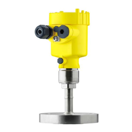
Housing cover, optionally available with indicating and adjustment module The components are available in different versions. Fig. 1: Example of a VEGABAR 51 with flange connection DN 50 PN 40 and plastic housing Housing cover with integrated indicating and adjustment module (optional) Housing with electronics Process fitting with measuring cell... -
Page 9: Principle Of Operation
3.2 Principle of operation The VEGABAR 51 is a pressure transmitter with isolating diaphragm Application area for pressure measurement of highly corrosive and hot liquids. The sensor element for measuring ranges up to 60 bar is the Functional principle ®... -
Page 10: Operation
(Electronic Device Description) is also required to enable the full range of sensor functions (also available as a download).A CD with the appropriate files can be ordered via e-mail under info@de.vega.com or by phone from one of the VEGA agencies under the order number "DRIVER.S". 3.3 Operation VEGABAR 51 can be adjusted with different adjustment media:... -
Page 11: Accessory And Replacement Parts
Interface adapter communication-capable instruments to the USB interface of a PC. For parameter adjustment of these instruments, an adjustment software such as PACTware with VEGA-DTM is required. You find further information in the operating instructions "Interface adapter VEGACONNECT" (Document-ID 32628). - Page 12 The electronics module is a replacement part for pressure transmitter VEGABAR. One version is available for each type of signal output. You find further information in the operating instructions "Electronics module VEGABAR series 50 and 60 " (Document-ID 30175). VEGABAR 51 • Profibus PA...
-
Page 13: Mounting
Rain and condensation water can thus drain off. This applies mainly to outdoor mounting as well as installation in areas where high humidity is expected (e.g. through cleaning processes) or on cooled or heated vessels. Fig. 2: Measures against moisture penetration VEGABAR 51 • Profibus PA... - Page 14 Temperature limits Higher process temperatures often mean also higher ambient temperatures. Make sure that the upper temperature limits stated in chapter "Technical data" for the environment of the electronics housing and connection cable are not exceeded. VEGABAR 51 • Profibus PA...
-
Page 15: Mounting Steps
Contamination by oil, grease and dirt should be avoided. Danger of explosion! 4.2 Mounting steps For mounting VEGABAR 51, a welded socket is required. You can find Welding the socket these components in the supplementary instructions manual "Welded socket and seals". -
Page 16: Mounting Steps, Tube Isolating Diaphragm
Position VEGABAR 51 with tube isolating diaphragm Tighten the threaded fittings step-by-step once on the right and on the left Hold VEGABAR 51, to avoid distortion from the defined installation position. Caution: Apart from mounting, the tube isolating diaphragm must not be permanently under torsion. - Page 17 The socket housing can be displaced by 180° to the wall mounting plate. Warning: The four screws of the socket housing must only be hand-screwed. A torque > 5 Nm (3.688 lbf ft) can damage the wall mounting plate. VEGABAR 51 • Profibus PA...
-
Page 18: Connecting To Power Supply
If overvoltage surges are expected, overvoltage arresters should be installed according to Profibus specifications Tip: We recommend VEGA overvoltage arrester B63-32. In hazardous areas you should take note of the appropriate regulations, conformity and type approval certificates of the sensors and power supply units. -
Page 19: Connection Procedure
Press down the opening levers of the terminals, you will hear the terminal spring closing Check the hold of the wires in the terminals by lightly pulling on them 10 Connect the screen to the internal ground terminal, connect the outer ground terminal with potential equalisation VEGABAR 51 • Profibus PA... - Page 20 The electrical connection is finished. Fig. 6: Connection steps 6 and 7 IP 68 version with exter- Proceed as follows: nal housing Loosen the four screws on the housing socket with an Allen key size 4 VEGABAR 51 • Profibus PA...
- Page 21 Remove approx. 5 cm of the cable mantle, strip approx. 1 cm insulation from the ends of the individual wires. After shortening the cable, fasten the type plate with sup- port back onto the cable. VEGABAR 51 • Profibus PA...
-
Page 22: Wiring Plan, Single Chamber Housing
Spring-loaded terminals for connection of the external indication VEGADIS Ground terminal for connection of the cable screen Spring-loaded terminals for voltage supply Wiring plan Display I 2 C Fig. 9: Wiring plan, single chamber housing Voltage supply/Signal output VEGABAR 51 • Profibus PA... -
Page 23: Wiring Plan, Double Chamber Housing
Electronics compart- ment Display I ² C 5 6 7 8 Fig. 10: Electronics compartment, double chamber housing Plug connector for VEGACONNECT (I²C interface) Internal connection cable to the connection compartment Terminals for VEGADIS 61 VEGABAR 51 • Profibus PA... - Page 24 Plug connector for VEGACONNECT (I²C interface) Ground terminal for connection of the cable screen Spring-loaded terminals for voltage supply Wiring plan I 2 C Fig. 12: Wiring plan with double chamber housing Voltage supply/Signal output VEGABAR 51 • Profibus PA...
-
Page 25: Wiring Plan Double Chamber Housing Ex D
Internal connection cable to the connection compartment Terminals for VEGADIS 61 Connection compart- ment Fig. 14: Connection compartment double chamber housing Ex d Spring-loaded terminals for power supply and cable screen Ground terminal for connection of the cable screen VEGABAR 51 • Profibus PA... -
Page 26: Wiring Plan - Version Ip 66/Ip 68, 1 Bar
5.6 Wiring plan - version IP 66/IP 68, 1 bar Wire assignment, con- nection cable Fig. 16: Wire assignment, connection cable brown (+) and blue (-) to power supply or to the processing system Shielding VEGABAR 51 • Profibus PA... -
Page 27: Wiring Plan, External Housing With Version Ip 68
5 Connecting to power supply 5.7 Wiring plan, external housing with version IP 68 Overview Fig. 17: VEGABAR 51 in IP 68 version 25 bar and axial cable outlet, external housing Electronics and connec- tion compartment for power supply I ² C Fig. -
Page 28: Switch On Phase
Fig. 20: Wiring plan external electronics Power supply 5.8 Switch on phase After VEGABAR 51 is connected to voltage supply or after voltage Switch on phase recurrence, the instrument carries out a self-check for approx. 30 seconds. The following steps are carried out:... - Page 29 Then the current measured value will be displayed and the corresponding digital output signal will be outputted to the cable. The values correspond to the actual measured level as well as to the set- tings already carried out, e.g. default setting. VEGABAR 51 • Profibus PA...
-
Page 30: Set Up With The Indicating And Adjustment Module Plicscom
Screw housing cover with inspection window tightly back on Removal is carried out in reverse order. The indicating and adjustment module is powered by the sensor, an additional connection is not necessary. VEGABAR 51 • Profibus PA... - Page 31 Fig. 21: Insert indicating and adjustment module Note: If you intend to retrofit the instrument with an indicating and adjustment module for continuous measured value indication, a higher cover with an inspection glass is required. VEGABAR 51 • Profibus PA...
-
Page 32: Adjustment System
The functions of the individual keys are shown in the above illustration. Approx. 10 minutes after the last pressing of a key, an automatic reset to measured value indication is triggered. Any values not confirmed with [OK] will not be saved. VEGABAR 51 • Profibus PA... -
Page 33: Setup Procedure
PACTware or DTM. VEGABAR 51 can be used for level as well as for process pressure Level or process pres- sure measurement measurement. - Page 34 Confirm with [OK], the submenu "Density unit" appears. Unit of measurement Density unit ▶ kg/dm³ Select the requested unit, e.g. kg/dm³ with [->] and confirm with [OK], the submenu "Density" appears. Selection options: mbar, bar, psi, Pa, kPa, MPa, inHg, mmHg, inH VEGABAR 51 • Profibus PA...
- Page 35 Edit the % value in the menu item "Min. adjustment" with [OK]. Min. adjustment +000.0 % +0000.0 mbar 0000.0 mbar Set the requested percentage value with [+] and [->]. Edit the requested mbar value with [OK]. Selection options: °C, °F. VEGABAR 51 • Profibus PA...
- Page 36 The editing procedure can be aborted with [ESC] or the displayed limit value can be accepted with [OK]. Process pressure measurement Set up VEGABAR 51 in the following sequence: Parameter ad- justment "Proc- Select application "Process pressure measurement"...
- Page 37 The actual measured value is displayed in addition to the menu items for zero/span adjustment. VEGABAR 51 is preset to application "Level measurement". Proceed Select application "Process pressure as follows when switching over to application "Process pressure measurement"...
- Page 38 Activate in the menu item "Position correction" the selection with [OK]. Position correction Offset +0000 mbar 53 mbar Select with [->], e.g. to accept actual measured value. Selection options: mbar, bar, psi, Pa, kPa, MPa, inHg, mmHg, inH Selection options: °C, °F. VEGABAR 51 • Profibus PA...
- Page 39 0000.0 mbar Information: The displayed pressure for 100 % corresponds to the nominal measuring range of the sensor (in the above example 1 bar = 1000 mbar). Set the requested mbar value with [->] and [OK]. VEGABAR 51 • Profibus PA...
- Page 40 [->] key. Caution: Note the following, if VEGABAR 51 is used as part of an overfill protection system according to WHG: If a linearisation curve is selected, the measuring signal is no longer compulsorily linear proportional to the level.
- Page 41 Decimal point indication The values of the following menu items are not reset with "Reset: Menu section Function Reset value Basic settings Position correction no reset Display Lighting no reset Service Language no reset Sensor-specific basic adjustment. VEGABAR 51 • Profibus PA...
- Page 42 You will find a detailed description of these menu items in the operating instructions manual "Indicating and adjustment module". Special parameters are parameters which are set customer-specifically on the service level with the adjustment software PACTware. VEGABAR 51 • Profibus PA...
-
Page 43: Menu Schematic
Displayed value Lighting ▼ PA-Out Switched off Diagnostics Basic adjustment Display ▶ Diagnostics Service Info 3.3.1 Pointer Sensor status Trend curve p-min.: -5.8 mbar p-max.: 167.5 mbar Start trend curve? T-min.: -12.5 °C T-max.: +85.5 °C VEGABAR 51 • Profibus PA... - Page 44 ▼ Level Info Basic adjustment Display Diagnostics Service ▶ Info Instrument type Date of manufacture Last change using PC Sensor characteristics 21. January 2009 Software version Display now? 3.50 21. January 2009 Serial number 12345678 VEGABAR 51 • Profibus PA...
-
Page 45: Saving The Parameter Adjustment Data
They are hence available for multiple use or service purposes. If VEGABAR 51 is equipped with an indicating and adjustment module, the most important data can be read out of the sensor into indicating and adjustment module. -
Page 46: Setup With Pactware And Other Adjustment Programs
USB cable to the PC VEGACONNECT Sensor VEGACONNECT exter- nally TWIST Fig. 24: Connection via VEGACONNECT externally I²C bus (com.) interface on the sensor I²C connection cable of VEGACONNECT VEGACONNECT USB cable to the PC VEGABAR 51 • Profibus PA... -
Page 47: Parameter Adjustment With Pactware
A detailed description is available in the online help of PACTware and the VEGA DTMs. Note: Keep in mind that for setup of VEGABAR 51, DTM-Collection in the actual version must be used. All currently available VEGA DTMs are included as a DTM Collection on a CD. -
Page 48: Maintenance And Fault Rectification
DTM. In many cases, the causes can be determined this way and faults rectified. 24 hour service hotline However, should these measures not be successful, call the VEGA service hotline in urgent cases under the phone no. +49 1805 858550. VEGABAR 51 • Profibus PA... - Page 49 Instrument not connected to the segment, double assignment of an address à Check and correct, if necessary In Ex applications, the regulations for the wiring of intrinsically safe circuits must be observed. VEGABAR 51 • Profibus PA...
-
Page 50: Exchanging The Electronics Module
These are not included in the electronics module without serial number. The serial number is stated on the type label of VEGABAR 51 or on the delivery note. 8.4 Software update... -
Page 51: Instrument Repair
Connect the sensor to power supply and provide connection from PC to the instrument via VEGACONNECT. Start PACTware and provide connection to the sensor, e.g. via the VEGA project assistant. Close the parameter window of the sensor, as far as open. -
Page 52: Dismount
Correct disposal avoids negative effects to persons and environment and ensures recycling of useful raw materials. Materials: see chapter "Technical data" If you have no possibility to dispose of the old instrument professionally, please contact us concerning return and disposal. VEGABAR 51 • Profibus PA... -
Page 53: Supplement
0.8 … 8 kg (1.764 … 17.64 lbs), depending on Weight approx. process fitting Output variable Output signal digital output signal, format according to IEEE-754 126 (default setting) Sensor address 10 mA, ±0.5 mA Current value VEGABAR 51 • Profibus PA... - Page 54 Adjustment range of the min./max. adjustment relating to the nominal measuring range: -10 … 110 % Percentage value -20 … 120 % Pressure value Adjustment range of the zero/span adjustment relating to the nominal measuring range: -20 … +95 % zero VEGABAR 51 • Profibus PA...
- Page 55 0 bar abs. 0 … 100 bar/0 … 10 MPa 200 bar/20000 kPa 0 bar abs. 0 … 400 bar/0 … 40 MPa 800 bar/80000 kPa 0 bar abs. Values less than -1 bar cannot be set. VEGABAR 51 • Profibus PA...
- Page 56 Long-term drift of the zero signal < (0.1 % x TD)/year Ambient conditions Ambient, storage and transport temperature Standard version -40 … +80 °C (-40 … +176 °F) Incl. non-linearity, hysteresis and non-repeatability. VEGABAR 51 • Profibus PA...
- Page 57 High temperature oil KN3.2 and cooling -10 … +300 °C/-10 … +200 °C (+14 … +572 °F/ element +14 … +572 °F) Up to 60 °C (140 °F). Version for oxygen applications up to 60 °C (140 °F). VEGABAR 51 • Profibus PA...
- Page 58 2 x blind stopper M20 x 1.5; plug M12 x 1 for VEGADIS 61 (optional) Tested according to the regulations of German Lloyd, GL directive 2. Tested according to EN 60068-2-27. Depending on the version M12 x 1, according to DIN 43650, Harting, 7/ 8" FF. VEGABAR 51 • Profibus PA...
- Page 59 2.5 mm² (AWG 14) Spring-loaded terminals for wire cross-sec- tion up to Connection cable between IP 68 instrument and external housing: Depending on the version M12 x 1, according to DIN 43650, Harting, 7/ 8" FF. VEGABAR 51 • Profibus PA...
- Page 60 FM or CSA. From measuring range 100 bar, 13 … 32 V DC. From measuring range 100 bar, 13 … 32 V DC. From measuring range 100 bar, 13 … 32 V DC. VEGABAR 51 • Profibus PA...
- Page 61 Depending on the version, instruments with approvals can have different technical data. For these instruments, the corresponding approval documents have to be taken into account. These are part of the delivery or can be downloaded under www.vega.com via "VEGA Tools" and "serial number search" as well as via "Downloads" and "Approvals".
-
Page 62: Information On Profibus Pa
Profibus user organisation (PNO). This ID number is also included in the name of the GSD file. For VEGABAR 51 the ID number is 0 x 076F(hex) and the GSD file BR__076F.GSD. As an option to this manufacturer-specific GSD file, PNO provides also a general so-called profile- specific GSD file. - Page 63 Target Source for Scaling Alarms Damping mode Mode scaling PA-Out Select additional cyclic value Fig. 26: VEGABAR 51: Block diagram with AI (PA-OUT) value and Additional Cyclic Value Sensor characteristics PROFIBUS PA-output Failure Target Source for Scaling Alarms Damping mode...
- Page 64 Flieskommazahl Status Status Value Temperature Status Additional Cyclic PA-OUT (FB1) (FB2) (FB2) (FB1) Value Fig. 28: Telegram configuration example 1 Example 2 with pressure value and temperature value without additional cyclical value: AI (PA-OUT) Temperature VEGABAR 51 • Profibus PA...
- Page 65 Fig. 31: Data format of the output signal The status byte corresponds to profile 3.0 "Profibus PA Profile for Process Control Devices" coded. The status "Measured value OK" is coded as 80 (hex) (Bit7 = 1, Bit6 … 0 = 0). VEGABAR 51 • Profibus PA...
- Page 66 (non-cascade) - active Static revision (FB, TB) changed (10 sec. active, after the parameter block alarm of the static category was written) 0 x 89 good (non-cascade) - active ad- Lo-Alarm visory alarm - low limited VEGABAR 51 • Profibus PA...
- Page 67 (non-cascade) - active ad- Hi-Alarm visory alarm - high limited 0 x 8d good (non-cascade) - active crit- Lo-Lo-Alarm ical alarm - low limited 0 x 8e good (non-cascade) - active crit- Hi-Hi-Alarm ical alarm - high limited VEGABAR 51 • Profibus PA...
-
Page 68: Dimensions
The following dimensional drawings represent only an extract of the possible versions. Detailed dimensional drawings can be downloaded on www.vega.com under "Downloads" and "Drawings". The two chamber housings are not available with instruments with 4 … 20 mA signal output... - Page 69 ø 84 mm ø 80 mm ø 77 mm (3.31") (3.15") (3.03") M16x1,5 M20x1,5/ ½ NPT M20x1,5/ M20x1,5/ ½ NPT ½ NPT Single chamber version, electropolished Single chamber version, precision casting Double chamber version, precision casting VEGABAR 51 • Profibus PA...
- Page 70 IP 68 version with external housing 65 mm ") 42mm ") 40mm ") 90 mm (3 ") 110 mm (4 ") ~ 66 mm (2 ") Fig. 38: IP 68 version with external housing Lateral cable outlet Axial cable outlet VEGABAR 51 • Profibus PA...
- Page 71 " 5“ " 3" " " 6“ 4xø " 5“ " 6" 2,9" 3" Fig. 39: VEGABAR 51 - flange version Flange connection according to DIN 2501 Flange fitting according to ANSI B16.5 Diaphragm diameter VEGABAR 51 • Profibus PA...
- Page 72 3" " " 4xø " " 3" " " 4xø " " 6" 2,9" Fig. 40: VEGABAR 51 - flange version Flange connection according to DIN 2501 Flange fitting according to ANSI B16.5 Diaphragm diameter VEGABAR 51 • Profibus PA...
- Page 73 Rd52x1,6 " " 2 " 1 " Rd58x1,6 Rd78x1,6 " 2 " 1 " Fig. 41: VEGABAR 51 - tube isolating diaphragm Tube isolating diaphragm for mounting between flanges, cell design Tube isolating diaphragm Tri-Clamp VEGABAR 51 • Profibus PA...
- Page 74 " " 7 " 3 Rd110x " Fig. 42: VEGABAR 51 - tube isolating diaphragm Tube isolating diaphragm with threaded socket according to DIN 11851 Tube isolating diaphragm with threaded socket according to DIN 11864-1 VEGABAR 51 • Profibus PA...
- Page 75 VEGABAR 51 - tube isolating diaphragm 3 128 mm ") Fig. 43: VEGABAR 51 - tube isolation diaphragm - ECO VEGABAR 51 - hygienic fitting ø 78 mm ") Fig. 44: VEGABAR 51 - RV = bolting according to DIN 11851 VEGABAR 51 • Profibus PA...
- Page 76 " " Fig. 45: VEGABAR 51 - ZA = cell isolating diaphragm DN 25/PN 16, ZB = cell isolating diaphragm DN 40/PN 16, ZC = cell isolating diaphragm DN 50/PN 16, ZD = cell isolating diaphragm DN 80/PN 16 VEGABAR 51 • Profibus PA...
- Page 77 ø 32 mm (0.98") (1.26") ø 39 mm (1.54") SW55 SW55 G1½B 1½”NPT ø 40 mm ø 40 mm (1.58") (1.58") ø 60 mm ø 60 mm (2.36") (2.36") GD/GF Fig. 46: VEGABAR 51 - threaded version VEGABAR 51 • Profibus PA...
- Page 78 SW27 ø 26 mm ") Fig. 47: VEGABAR 51 - threaded version with temperature adapter. The length depends on the respective temperature stage, e.g. L = 152 mm (6 in) at 200 °C (392 °F) VEGABAR 51 • Profibus PA...
- Page 79 Les lignes de produits VEGA sont globalement protégées par des droits de propriété intellectuelle. Pour plus d'informations, on pourra se référer au site http://www.vega. VEGA lineas de productos están protegidas por los derechos en el campo de la propiedad industrial. Para mayor información revise la pagina web http://www.vega.com Линии...
- Page 80 Wiring plan - Double chamber 24 - Double chamber Ex d 26 Install - External electronics 28 - Flange versions 15 - Single chamber 22 - Hygienic ttings 16 Zero adjustment 39 Linearisation curve 40 VEGABAR 51 • Profibus PA...
- Page 81 Index VEGABAR 51 • Profibus PA...
- Page 82 Index VEGABAR 51 • Profibus PA...
- Page 83 Index VEGABAR 51 • Profibus PA...
- Page 84 All statements concerning scope of delivery, application, practical use and operating conditions of the sensors and processing systems correspond to the information avail- able at the time of printing. © VEGA Grieshaber KG, Schiltach/Germany 2009 36714-EN-091008 Subject to change without prior notice...
Need help?
Do you have a question about the VEGABAR 51 and is the answer not in the manual?
Questions and answers