Vega VEGABAR 51 Operating Instructions Manual
Foundation fieldbus
Hide thumbs
Also See for VEGABAR 51:
- Product information (32 pages) ,
- Operating instructions manual (84 pages)

Related Manuals for Vega VEGABAR 51


Summary of Contents for Vega VEGABAR 51
- Page 1 Operating Instructions VEGABAR 51 Foundation Fieldbus Document ID: 36715 Process pressure...
-
Page 2: Table Of Contents
Menu schematic ......42 Saving the parameter adjustment data ... . 44 VEGABAR 51 • Foundation Fieldbus... - Page 3 10.3 Dimensions ....... 66 Supplementary documentation Information: Supplementary documents appropriate to the ordered version come with the delivery. You can find them listed in chapter "Product description". Editing status: 2011-06-20 VEGABAR 51 • Foundation Fieldbus...
-
Page 4: About This Document
This symbol indicates special instructions for Ex applications. List The dot set in front indicates a list with no implied sequence. à Action This arrow indicates a single action. Sequence Numbers set in front indicate successive steps in a procedure. VEGABAR 51 • Foundation Fieldbus... -
Page 5: For Your Safety
During work on and with the device the required personal protective equipment must always be worn. 2.2 Appropriate use VEGABAR 51 is a pressure transmitter for measurement of gauge pressure, absolute pressure and vacuum. You can find detailed information on the application range in chapter "Product description". -
Page 6: Safety Label On The Instrument
2.6 CE conformity This device fulfills the legal requirements of the applicable EC guidelines. By attaching the CE mark, VEGA provides a confirmation of successful testing. You can find the CE conformity declaration in the download area of www.vega.com. -
Page 7: Environmental Instructions
The environment management system is certified according to DIN EN ISO 14001. Please help us fulfil this obligation by observing the environmental instructions in this manual: Chapter "Packaging, transport and storage" Chapter "Disposal" VEGABAR 51 • Foundation Fieldbus... -
Page 8: Product Description
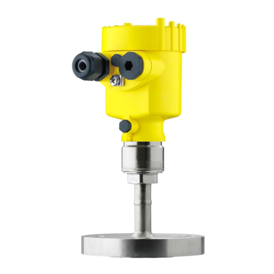
Housing cover, optionally available with indicating and adjustment module The components are available in different versions. Fig. 1: Example of a VEGABAR 51 with flange connection DN 50 PN 40 and plastic housing Housing cover with integrated indicating and adjustment module (optional) Housing with electronics Process fitting with measuring cell... -
Page 9: Principle Of Operation
The optional label contains references to the oil, grease and silicone-free parts of the instrument. 3.2 Principle of operation The VEGABAR 51 is a pressure transmitter with isolating diaphragm Application area for pressure measurement of highly corrosive and hot liquids. -
Page 10: Configuration
Foundation Fieldbus". The appropriate certificates are also available there. A CD with the appropriate files and certificates can be ordered via e-mail under info@de.vega.com or by phone from one of the VEGA agencies under the order number "DRIVER.S". The backlight of the indicating and adjustment module is powered by the sensor. -
Page 11: Accessories And Replacement Parts
Interface adapter communication-capable instruments to the USB interface of a PC. For parameter adjustment of these instruments, an adjustment software such as PACTware with VEGA-DTM is required. You can find further information in the operating instructions "Interface adapter VEGACONNECT" (Document-ID 32628). - Page 12 The electronics module is a replacement part for pressure transmitter VEGABAR. One version is available for each type of signal output. You find further information in the operating instructions "Electronics module VEGABAR series 50 and 60 " (Document-ID 30175). VEGABAR 51 • Foundation Fieldbus...
-
Page 13: Mounting
Rain and condensation water can thus drain off. This applies mainly to outdoor mounting as well as installation in areas where high humidity is expected (e.g. through cleaning processes) or on cooled or heated vessels. Fig. 3: Measures against moisture penetration VEGABAR 51 • Foundation Fieldbus... - Page 14 Temperature limits Higher process temperatures often mean also higher ambient temperatures. Make sure that the upper temperature limits stated in chapter "Technical data" for the environment of the electronics housing and connection cable are not exceeded. VEGABAR 51 • Foundation Fieldbus...
-
Page 15: Mounting Steps
Danger: Avoid oil, grease or contamination. Explosion danger! 4.2 Mounting steps For mounting VEGABAR 51, a welded socket is required. You can find Welding the socket these components in the supplementary instructions manual "Welded socket and seals". Sealing/Screwing in Seal the thread with teflon, hemp or a similar resistant seal material on... -
Page 16: Mounting Steps, Tube Isolating Diaphragm
Position VEGABAR 51 with tube isolating diaphragm Tighten the threaded fittings step-by-step once on the right and on the left Hold VEGABAR 51, to avoid distortion from the defined installation position. Caution: Apart from mounting, the tube isolating diaphragm must not be permanently under torsion. - Page 17 The socket housing can be displaced by 180° to the wall mounting plate. Warning: The four screws of the socket housing must only be hand screwed. A torque > 5 Nm (3.688 lbf ft) can damage the wall mounting plate. VEGABAR 51 • Foundation Fieldbus...
-
Page 18: Connecting To Power Supply
If overvoltage surges are expected, overvoltage arresters should be installed according to Foundation Fieldbus specification Tip: We recommend VEGA overvoltage arrester B63-32. In hazardous areas you must take note of the respective regulations, conformity and type approval certificates of the sensors and power supply units. -
Page 19: Connection Procedure
10 Connect the screen to the internal ground terminal, connect the outer ground terminal to potential equalisation 11 Tighten the compression nut of the cable entry. The seal ring must completely encircle the cable 12 Screw the housing cover on VEGABAR 51 • Foundation Fieldbus... - Page 20 Loosen the four screws on the housing base with an Allen key size Remove the housing socket from the mounting plate Fig. 8: Components of the external housing Screws Wall mounting plate Cable gland VEGABAR 51 • Foundation Fieldbus...
-
Page 21: Wiring Plan, Single Chamber Housing
Remove approx. 5 cm of the cable mantle, strip approx. 1 cm insulation from the ends of the individual wires. After shortening the cable, fasten the type plate with sup- port back onto the cable. VEGABAR 51 • Foundation Fieldbus... -
Page 22: Wiring Plan, Double Chamber Housing
Wiring plan Display I 2 C Fig. 10: Wiring plan, single chamber housing Voltage supply/Signal output 5.4 Wiring plan, double chamber housing The following illustrations apply to the non-Ex as well as to the Ex-ia version. VEGABAR 51 • Foundation Fieldbus... - Page 23 Internal connection cable to the connection compartment Connection compart- ment I ² C Fig. 12: Connection compartment, double chamber housing Plug connector for VEGACONNECT (I²C interface) Ground terminal for connection of the cable screen Spring-loaded terminals for voltage supply VEGABAR 51 • Foundation Fieldbus...
-
Page 24: Wiring Plan With Double Chamber Housing Ex D
Display I ² C 5 6 7 8 Fig. 14: Electronics compartment, double chamber housing Simulation switch ("on" = mode for simulation release) Connection for VEGACONNECT (I²C interface) Internal connection cable to the connection compartment VEGABAR 51 • Foundation Fieldbus... - Page 25 Fig. 15: Connection compartment with double chamber housing Ex d Spring-loaded terminals for power supply and cable screen Ground terminal for connection of the cable screen Wiring plan Fig. 16: Wiring plan with double chamber housing Ex d Voltage supply/Signal output VEGABAR 51 • Foundation Fieldbus...
-
Page 26: Wiring Plan - Version Ip 66/Ip 68, 1 Bar
(+) and blue (-) to power supply or to the processing system Shielding 5.7 Wiring plan, external housing with version IP 68 Overview Fig. 18: VEGABAR 51 in IP 68 version 25 bar and axial cable outlet, external housing VEGABAR 51 • Foundation Fieldbus... - Page 27 Spring-loaded terminals for connection of the external indication VEGADIS Cable gland to the sensor Ground terminal for connection of the cable screen Spring-loaded terminals for Foundation Fieldbus connection Simulation switch ("on" = mode for simulation release) VEGABAR 51 • Foundation Fieldbus...
-
Page 28: Switch On Phase
Fig. 21: Wiring plan external electronics Voltage supply 5.8 Switch on phase After VEGABAR 51 is connected to voltage supply or after voltage Switch on phase recurrence, the instrument carries out a self-check for approx. 30 seconds. The following steps are carried out:... - Page 29 Then the current measured value will be displayed and the corresponding digital output signal will be outputted to the cable. The values correspond to the actual measured level as well as to the set- tings already carried out, e.g. default setting. VEGABAR 51 • Foundation Fieldbus...
-
Page 30: Set Up With The Indicating And Adjustment Module Plicscom
Screw housing cover with inspection window tightly back on Removal is carried out in reverse order. The indicating and adjustment module is powered by the sensor, an additional connection is not necessary. VEGABAR 51 • Foundation Fieldbus... - Page 31 Fig. 22: Insert indicating and adjustment module Note: If you intend to retrofit the instrument with an indicating and adjustment module for continuous measured value indication, a higher cover with an inspection glass is required. VEGABAR 51 • Foundation Fieldbus...
-
Page 32: Adjustment System
The functions of the individual keys are shown in the above illustration. Approx. 10 minutes after the last pressing of a key, an automatic reset to measured value indication is triggered. Any values not confirmed with [OK] will not be saved. VEGABAR 51 • Foundation Fieldbus... -
Page 33: Setup Steps
6 Set up with the indicating and adjustment module PLICSCOM 6.4 Setup steps VEGABAR 51 can be used for level as well as for process pressure Level or process press- ure measurement measurement. Default setting is level measurement. The mode can be changed in the adjustment menu. - Page 34 Unit of measurement Density 0001000 kg/dm³ Enter the requested density value with [->] and [+], confirm with [OK] and move to position correction with [->]. The adjustment unit is thus switched over from bar to m. VEGABAR 51 • Foundation Fieldbus...
- Page 35 Confirm with [+] and move to max. adjustment with [->]. The min. adjustment is finished. Information: For an adjustment with filling, simply enter the actual measured value indicated at the bottom of the display. Selection options: °C, °F. VEGABAR 51 • Foundation Fieldbus...
- Page 36 The editing procedure can be aborted with [ESC] or the displayed limit value can be accepted with [OK]. Process pressure measurement Set up VEGABAR 51 in the following sequence: Parameter ad- justment "Pro- Select application "Process pressure measurement"...
- Page 37 The actual measured value is displayed in addition to the menu items for zero/span adjustment. VEGABAR 51 is preset to application "Level measurement". Proceed Select application "Pro- cess pressure measure- as follows when switching over to application "Process pressure...
- Page 38 Accept Edit Confirm with [OK] and move to min.(zero) adjustment with [->]. Carrying out zero ad- Proceed as follows: justment Edit the mbar value in the menu item "zero" with [OK]. Selection options: °C, °F. VEGABAR 51 • Foundation Fieldbus...
- Page 39 If the adjustment ranges are exceeded, the message "Outside parameter limits" appears. The editing procedure can be aborted with [ESC] or the displayed limit value can be accepted with [OK]. VEGABAR 51 • Foundation Fieldbus...
- Page 40 Span/Max. adjustment Measuring range end 1 kg/l Density Density unit kg/l Damping Linearisation Linear Sensor-TAG Sensor Display Displayed value AI-Out The values of the following menu items are not reset with "Reset: Sensor-specific basic adjustment. VEGABAR 51 • Foundation Fieldbus...
- Page 41 You will find a detailed description of these menu items in the operating instructions manual "Indicating and adjustment module". Special parameters are parameters which are set customer-specifically on the service level with the adjustment software PACTware. VEGABAR 51 • Foundation Fieldbus...
-
Page 42: Menu Schematic
Lighting ▼ AI-Out Switched off Diagnostics Basic adjustment Display ▶ Diagnostics Service Info 3.3.1 Peak value Sensor status Trend curve p-min.: -5.8 mbar p-max.: 167.5 mbar Start trend curve? T-min.: -12.5 °C T-max.: +85.5 °C VEGABAR 51 • Foundation Fieldbus... - Page 43 Level Info Basic adjustment Display Diagnostics Service ▶ Info Device-ID Instrument type Calibration date Last change using PC 26. August 2010 Sensor-TAG Software version 3.82 26. August 2010 Serial number 12345678 Sensor characteristics Display now? VEGABAR 51 • Foundation Fieldbus...
-
Page 44: Saving The Parameter Adjustment Data
They are hence available for multiple use or service purposes. If VEGABAR 51 is equipped with an indicating and adjustment module, the most important data can be read out of the sensor into the indicating and adjustment module. -
Page 45: Set Up With Pactware And Other Adjustment Programs
USB cable to the PC VEGACONNECT Sensor VEGACONNECT exter- nally TWIST Fig. 25: Connection via VEGACONNECT externally I²C bus (com.) interface on the sensor I²C connection cable of VEGACONNECT VEGACONNECT USB cable to the PC VEGABAR 51 • Foundation Fieldbus... -
Page 46: Parameter Adjustment With Pactware
A detailed description is available in the online help of PACTware and the VEGA DTMs. Note: Keep in mind that for setup of VEGABAR 51, DTM-Collection in the actual version must be used. All currently available VEGA DTMs are included as a DTM Collection on a CD. -
Page 47: Maintenance And Fault Rectification
DTM. In many cases, the causes can be determined and the faults rectified this way. 24 hour service hotline Should these measures not be successful, please call in urgent cases the VEGA service hotline under the phone no. +49 1805 858550. VEGABAR 51 • Foundation Fieldbus... - Page 48 à repeat with modified values E036 no operable sensor software à Carry out a software update or send instrument for repair Fault message can also appear if the pressure is higher than the nominal range. VEGABAR 51 • Foundation Fieldbus...
-
Page 49: Exchanging The Electronics Module
These are not included in the electronics module without serial number. The serial number is stated on the type label of VEGABAR 51 or on the delivery note. 8.4 Software update... -
Page 50: Instrument Repair
Connect the sensor to power supply and provide connection from PC to the instrument via VEGACONNECT. Start PACTware and provide connection to the sensor, e.g. via the VEGA project assistant. Close the parameter window of the sensor, as far as open. -
Page 51: Dismounting
Correct disposal avoids negative effects on humans and the environ- ment and ensures recycling of useful raw materials. Materials: see chapter "Technical data" If you have no way to dispose of the old instrument properly, please contact us concerning return and disposal. VEGABAR 51 • Foundation Fieldbus... -
Page 52: Supplement
Connection cable with IP 68 1 bar version 0.8 … 8 kg (1.764 … 17.64 lbs), depending on Weight approx. process fitting Output variable Output Signal digital output signal, Foundation Fieldbus protocol according to IEC 61158-2 Physical layer VEGABAR 51 • Foundation Fieldbus... - Page 53 To this amounts the reaction time of the isolatng system. This time varies from values < 1 s with compact isolating diaphragms up to several seconds with capillary systems. Example: Flange isolating diaphragm DN 80, filling silicone oil KN 2.2, capillary length 10 m, measuring range 1 bar VEGABAR 51 • Foundation Fieldbus...
- Page 54 -1 bar/-100 kPa 0 … +60 bar/0 … +6000 kPa +200 bar/+20 MPa -1 bar/-100 kPa -1 … 0 bar/-100 … 0 kPa +10 bar/+1000 kPa -1 bar/-100 kPa Values less than -1 bar cannot be set. VEGABAR 51 • Foundation Fieldbus...
- Page 55 +507.6 psig -14.50 psig -14.50 … +145.0 psig -14.50 psig +1160 psig -14.50 … +362.6 psig +1160 psig -14.50 psig -14.50 … +870.2 psig +2901 psig -14.50 psig -2.901 … +2.901 psig +2.901 psig -14.50 psig VEGABAR 51 • Foundation Fieldbus...
- Page 56 < 0.05 %/10 K x TD In the compensated temperature range 0 … +100 °C (+32 … +212 °F) typ. < 0.05 %/10 K x TD Outside the compensated temperature range Incl. non-linearity, hysteresis and non-repeatability. VEGABAR 51 • Foundation Fieldbus...
- Page 57 Temperature coefficient of the isolating diaphragm in mbar/10 K with Flange DN 50 PN 40, Form C, DIN 2501 1.2 mbar/10 K Flange DN 80 PN 40, Form C, DIN 2501 0.25 mbar/10 K Up to 60 °C (140 °F). VEGABAR 51 • Foundation Fieldbus...
- Page 58 +14 … +320 °F) mechanical vibrations with 4 g and 5 … 100 Hz Vibration resistance Version for oxygen applications up to 60 °C (140 °F). Tested according to the guidelines of German Lloyd, GL directive 2. VEGABAR 51 • Foundation Fieldbus...
- Page 59 Connection cable Structure four wires, one suspension cable, one breather capillary, screen braiding, metal foil, mantle Tested according to EN 60068-2-27. Depending on the version M12 x 1, according to ISO 4400, Harting, 7/8" FF. VEGABAR 51 • Foundation Fieldbus...
- Page 60 Adjustment elements Protection rating IP 20 unassembled IP 40 mounted into the sensor without cover Materials Housing Inspection window Polyester foil Depending on the version M12 x 1, according to ISO 4400, Harting, 7/8" FF. VEGABAR 51 • Foundation Fieldbus...
- Page 61 Instruments with approvals can have different technical data depending on the version. That's why the associated approval documents have to be noted with these instruments. They are part of the delivery or can be downloaded under www.vega.com via "VEGA Tools" and "serial number search" as well as via "Downloads" and "Approvals".
-
Page 62: Information On Foundation Fieldbus
Channel = 2: Secondary Value 1 Channel = 3: Secondary Value 2 AI 3 Channel = 4: Temperature Fig. 28: Transducer Block VEGABAR 51 TB Transducer Block Function Block (AI =Analogue Input) Diagram, adjustment The following illustration shows the function of the adjustment:... - Page 63 X and Y values for the user defined linearization curve curve_points_21_30 X and Y values for the user defined linearization curve curve_points_31_33 X and Y values for the user defined linearization curve curve status VEGABAR 51 • Foundation Fieldbus...
- Page 64 Sensor value after the trim processing. Unit derives from 'Sensor_range.unit' sensor_sn Sensor serial number temperature Process temperature. Selected as input to AIFB by setting 'Channel' = 4. Unit derives from 'Temperature.unit' temperature_unit Unit code of 'Temperature', 'Max/Min_peak_temperature_value' °C, °F, K, °R VEGABAR 51 • Foundation Fieldbus...
- Page 65 Holds the maximum process temperature. Write access resets to current value. Unit derives from 'Temperature.unit' Write access resets to current value min_peak_temperature_value Holds the minimum process temperature. Write access resets to current value. Unit derives from 'Temperature.unit' Write access resets to current value VEGABAR 51 • Foundation Fieldbus...
-
Page 66: Dimensions
The following dimensional drawings represent only an extract of the possible versions. Detailed dimensional drawings can be downloaded on www.vega.com under "Downloads" and "Drawings". The two chamber housings are not available with instruments with 4 … 20 mA signal output... - Page 67 Fig. 33: Housing versions in protection IP 66/IP 68 (0.2 bar) - with integrated indicating and adjustment module the housing is 9 mm/0.35 in higher Single chamber version, electropolished Single chamber version, precision casting Double chamber version, precision casting VEGABAR 51 • Foundation Fieldbus...
- Page 68 IP 68 (25 bar) version with external housing 65 mm ") 42mm ") 40mm ") 90 mm (3 ") 110 mm (4 ") ~ 66 mm (2 ") Fig. 35: IP 68 version with external housing Lateral cable outlet Axial cable outlet VEGABAR 51 • Foundation Fieldbus...
- Page 69 4 x ø19 3" 24,3 152,4 4 x ø19 152,5 3" 24,3 152,4 Fig. 36: VEGABAR 51 - Flange version, dimensions in mm Flange connection according to DIN 2501 Flange fitting according to ANSI B16.5 Diaphragm diameter VEGABAR 51 • Foundation Fieldbus...
- Page 70 4 x ø0.75" 6" 2.99" 2.84" 3" 7.48" 0.96" 6" 5" 0.08" Fig. 37: VEGABAR 51 - Flange version, dimensions in inch Flange connection according to DIN 2501 Flange fitting according to ANSI B16.5 Diaphragm diameter VEGABAR 51 • Foundation Fieldbus...
- Page 71 2.36 " Rd58x1,6 3.74 " 6…100 2.15 " 2.36 " 6.14" 1.97 " Rd78x1,6 Fig. 38: VEGABAR 51 - tube isolating diaphragm Tube isolating diaphragm for mounting between flanges Tube isolating diaphragm according to DIN 11851 VEGABAR 51 • Foundation Fieldbus...
- Page 72 RD28x 4.09 " 0.39 " RD44x 4.09 " 0.79 " Fig. 39: VEGABAR 51 - tube isolating diaphragm according to DIN 11864 - tube isolating diaphragm 3 VEGABAR 51 128 mm (5.04") Fig. 40: VEGABAR 51 - tube isolation diaphragm - ECO...
- Page 73 10 Supplement - hygienic fitting VEGABAR 51 Rd 65 x 1/6 Fig. 41: VEGABAR 51 - bolting according to DIN 11851 VEGABAR 51 • Foundation Fieldbus...
- Page 74 5.91" 0.71" 3.47" 4.33" ø Mb 0.71" 2.32" 6.5" 0.79" 4.02" 4.92" ø d4 7.87" 0.79" 5.43" 6.3" 0.71" 3.5" ø k ø D Fig. 42: VEGABAR 51 - Capillary line with flange isolating diaphragm VEGABAR 51 • Foundation Fieldbus...
- Page 75 1.26" 16..100 0.71" 2.68" 16..100 1.77" 0.71" 3.47" 16..100 0.79" 4.02" 2.32" ø 26 mm 16..100 0.79" 5.43" 3.5" (1.54") ø Mb ø d4 Fig. 43: VEGABAR 51 - Capillary line with cell isolating diaphragm VEGABAR 51 • Foundation Fieldbus...
- Page 76 (2.36") Fig. 44: VEGABAR 51 - Threaded version, GA = G½ A according to ISO 228-1, GB = G ¾A according to DIN 3852- E, GC = G1 A according to DIN 3852-E, GD = G1½ A according to DIN 3852-A...
- Page 77 10 Supplement - Threaded version with temperature adapter VEGABAR 51 SW 32 mm (1.26") G 1/2 B ø 26 mm (1.02") Fig. 45: VEGABAR 51 - Threaded version with temperature adapter VEGABAR 51 • Foundation Fieldbus...
- Page 78 Les lignes de produits VEGA sont globalement protégées par des droits de propriété intellectuelle. Pour plus d'informations, on pourra se référer au site http://www.vega. VEGA lineas de productos están protegidas por los derechos en el campo de la propiedad industrial. Para mayor información revise la pagina web http://www.vega.com Линии...
- Page 79 Zero adjustment 38 Fault rectification 47 Hotline 47 Max. adjustment 36 Min. adjustment 35 Moisture 13 Mounting external housing 16 Mounting position 13 Oxygen applications 15 Position correction 35, 38 Pressure compensation 14 Process conditions 13 VEGABAR 51 • Foundation Fieldbus...
- Page 80 All statements concerning scope of delivery, application, practical use and operating conditions of the sensors and processing systems correspond to the information avail- able at the time of printing. © VEGA Grieshaber KG, Schiltach/Germany 2011 36715-EN-110629 Subject to change without prior notice...
Need help?
Do you have a question about the VEGABAR 51 and is the answer not in the manual?
Questions and answers