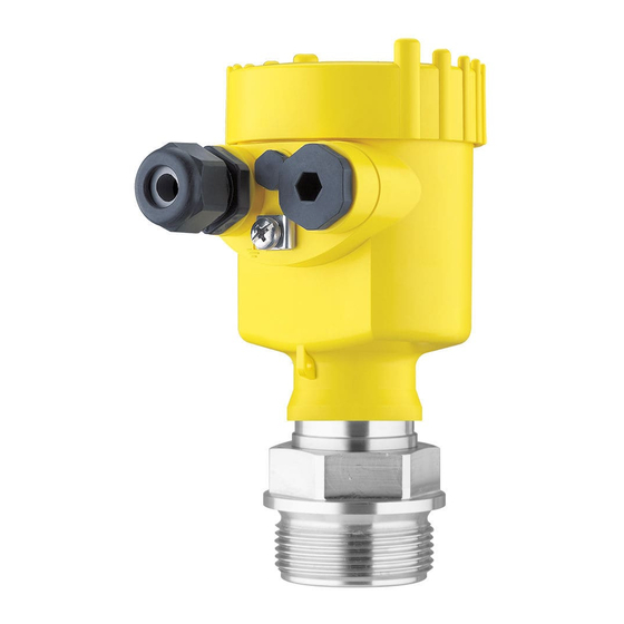
Vega VEGABAR 82 Quick Setup Manual
4 ... 20 ma/hart
Hide thumbs
Also See for VEGABAR 82:
- Operating instructions manual (104 pages) ,
- Quick setup manual (24 pages) ,
- Product information (16 pages)

Subscribe to Our Youtube Channel
Related Manuals for Vega VEGABAR 82


Summary of Contents for Vega VEGABAR 82
- Page 1 Quick setup guide Pressure transmitter with ceramic measuring cell VEGABAR 82 4 … 20 mA/HART Document ID: 46306...
-
Page 2: Table Of Contents
You can find supplementary information in the corresponding, more detailed Operating Instructions Manual as well as the Safety Manual that comes with instruments with SIL qualification. These manuals are available in the download area of "www.vega.com". Operating instructions VEGABAR 82 - 4 … 20 mA/HART: Document-ID 45028 Editing status of the quick setup guide: 2019-04-02... -
Page 3: For Your Safety
1 For your safety For your safety Authorised personnel All operations described in this documentation must be carried out only by trained, qualified personnel authorised by the plant operator. During work on and with the device, the required personal protective equipment must always be worn. Appropriate use The VEGABAR 82 is a pressure transmitter for process pressure and hydrostatic level measurement. You can find detailed information about the area of application in chapter "Product description". -
Page 4: Eu Conformity
1 For your safety EU conformity The device fulfils the legal requirements of the applicable EU direc- tives. By affixing the CE marking, we confirm the conformity of the instrument with these directives. You can find the EU conformity declaration on our website under www.vega.com/downloads. Permissible process conditions For safety reasons, the instrument must only be operated within the permissible process conditions. You can find detailed information on the process conditions in chapter "Technical data" as well as on the type label. The permissible process pressure range is specified by "MWP" (Maximum Working Pressure) on the type label, see chapter "Struc- ture". The MWP takes the element of the measuring cell and process- ing fitting combination with the weakest pressure into consideration and may applied permanently. The specification refers to a reference... - Page 5 1 For your safety tection. The environment management system is certified according to DIN EN ISO 14001. Please help us fulfil this obligation by observing the environmental instructions in this manual: • Chapter "Packaging, transport and storage" • Chapter "Disposal" VEGABAR 82 • 4 … 20 mA/HART...
-
Page 6: Product Description
Test certificate (PDF) - optional Move to "www.vega.com" and enter in the search field the serial number of your instrument. Alternatively, you can access the data via your smartphone: • Download the VEGA Tools app from the "Apple App Store" or the "Google Play Store" • Scan the Data Matrix code on the type label of the instrument or •... -
Page 7: Mounting
3 Mounting Mounting General instructions for use of the instrument Protection against mois- Protect your instrument against moisture ingress through the following ture measures: • Use a suitable connection cable (see chapter "Connecting to power supply") • Tighten the cable gland or plug connector •... - Page 8 3 Mounting • Instruments in protection IP 66/IP 68 (1 bar) - ventilation via capil- laries in non-detachable cable • Instruments with absolute pressure VEGABAR 82 • 4 … 20 mA/HART...
-
Page 9: Connecting To Power Supply
4 Connecting to power supply Connecting to power supply Connecting Connection technology The voltage supply and signal output are connected via the spring- loaded terminals in the housing. Connection to the display and adjustment module or to the interface adapter is carried out via contact pins in the housing. Information: The terminal block is pluggable and can be removed from the electronics. To do this, lift the terminal block with a small screwdriver... -
Page 10: Single Chamber Housing
4 Connecting to power supply 8. Connect the screen to the internal ground terminal, connect the external ground terminal to potential equalisation 9. Tighten the compression nut of the cable entry gland. The seal ring must completely encircle the cable 10. Reinsert the display and adjustment module, if one was installed 11. Screw the housing lid back on The electrical connection is finished. - Page 11 4 Connecting to power supply Connection compartment 4...20mA Display 6 7 8 Fig. 5: Connection compartment - double chamber housing Voltage supply, signal output For display and adjustment module or interface adapter For external display and adjustment unit Ground terminal for connection of the cable screening VEGABAR 82 •...
-
Page 12: Set Up With The Display And Adjustment Module
5 Set up with the display and adjustment module Set up with the display and adjustment module Insert display and adjustment module The display and adjustment module can be inserted into the sensor and removed again at any time. You can choose any one of four differ- ent positions - each displaced by 90°. It is not necessary to interrupt the power supply. -
Page 13: Parameter Adjustment - Quick Setup
5 Set up with the display and adjustment module Fig. 7: Installing the display and adjustment module in the double chamber housing In the electronics compartment In the connection compartment Note: If you intend to retrofit the instrument with a display and adjustment module for continuous measured value indication, a higher lid with an inspection glass is required. Parameter adjustment - Quick setup To quickly and easily adapt the sensor to the application, select the menu item "Quick setup"... - Page 14 5 Set up with the display and adjustment module Quick setup - Process 4. Position correction pressure measurement In this menu item you compensate the influence of the installation position of the instrument (offset) on the measured value. 5. Zero adjustment In this menu item you carry out the zero adjustment for the process pressure. Enter the corresponding pressure value for 0 %. 6. Span adjustment In this menu item you carry out the span adjustment for the process pressure Enter the corresponding pressure value for 100 %.
-
Page 15: Parameter Adjustment - Extended Adjustment
5 Set up with the display and adjustment module 100% Fig. 8: Parameter adjustment example "Min./max. adjustment, level measure- ment" Min. level = 0 % corresponds to 0.0 mbar Max. level = 100 % corresponds to 490.5 mbar If these values are not known, an adjustment with filling levels of e.g. 10 % and 90 % is also possible. By means of these settings, the real filling height is then calculated. -
Page 16: Menu Overview
5 Set up with the display and adjustment module Info: Instrument name, hardware and software version, date of manu- facture, sensor features Note: For optimum adjustment of the measuring point, the individual sub- menu items in the main menu item "Setup" should be selected one after the other and provided with the correct parameters. If possible, go through the items in the given sequence. The submenu points are described below. Menu overview Setup Menu item... - Page 17 5 Set up with the display and adjustment module Menu item Default setting Displayed value 2 Ceramic measuring cell: Measuring cell tempera- ture in °C Metallic measuring cell: Electronics temperature in °C Display format 1 and 2 Number of positions after the decimal point, auto- matically Backlight Switched on Diagnostics Menu item...
- Page 18 5 Set up with the display and adjustment module Menu item Parameter Factory calibration Date date Sensor characteristics Order-specific characteristics VEGABAR 82 • 4 … 20 mA/HART...
-
Page 19: Supplement
6 Supplement Supplement Technical data Note for approved instruments The technical data in the respective safety instructions are valid for approved instruments (e.g. with Ex approval). These data can differ from the data listed herein, for example regarding the process conditions or the voltage supply. Electromechanical data - version IP 66/IP 67 and IP 66/IP 68 (0.2 bar) Options of the cable entry Ʋ... - Page 20 6 Supplement Ʋ Example - Non-Ex instrument with (24 V - 9.6 V)/0.022 A = 655 Ω = 24 V DC VEGABAR 82 • 4 … 20 mA/HART...
- Page 21 Notes VEGABAR 82 • 4 … 20 mA/HART...
- Page 22 Notes VEGABAR 82 • 4 … 20 mA/HART...
- Page 23 Notes VEGABAR 82 • 4 … 20 mA/HART...
-
Page 24: Information
Subject to change without prior notice © VEGA Grieshaber KG, Schiltach/Germany 2019 VEGA Grieshaber KG Phone +49 7836 50-0 Am Hohenstein 113...
Need help?
Do you have a question about the VEGABAR 82 and is the answer not in the manual?
Questions and answers