Table of Contents
Advertisement
MicroTech Ι Ι Ι Ι Ι Ι Ι Ι ™ ™ ™ ™ Controller
With Starter Information
For Centrifugal Chillers and Templifiers™ ™ ™ ™
Models WSC, WDC, WCC, HSC, TSC
Software Version: WCFU3UU04C/D/E
OITS Version: 2.05.03
Operating Manual
OM CentrifMicro II-5
Group: Chiller
Part Number: 331374901
Effective: March 2011
Supersedes: November 2010
Advertisement
Table of Contents
Troubleshooting

Subscribe to Our Youtube Channel
Related Manuals for McQuay WSC


Summary of Contents for McQuay WSC
- Page 1 Supersedes: November 2010 MicroTech Ι Ι Ι Ι Ι Ι Ι Ι ™ ™ ™ ™ Controller With Starter Information For Centrifugal Chillers and Templifiers™ ™ ™ ™ Models WSC, WDC, WCC, HSC, TSC Software Version: WCFU3UU04C/D/E OITS Version: 2.05.03...
-
Page 2: Table Of Contents
McQuay" and MicroTech II are registered trademarks of McQuay International © 2005 McQuay International "Illustrations and information cover McQuay International products at the time of publication and we reserve the right to make changes in design and construction at anytime without notice." OM CentrifMicro II-5... -
Page 3: Introduction
Introduction This manual provides operating, maintenance and troubleshooting information for McQuay centrifugal chillers with MicroTech ΙΙ™ control and for the majority of starters used on McQuay centrifugal chillers. Software Version Software Code: WCFU3UU04C/D/E Notations stating previous content are made when a new version changes a previous value or statement. -
Page 4: Features Of The Control Panel
Features of the Control Panel • Control of leaving chilled water within a ±0.5°F (±0.3°C) tolerance. Systems with a large water volume and relatively slow load changes can do better. • Readout of the following temperature and pressure readings: • Entering and leaving chilled water temperature •... -
Page 5: General Description
General Description General Description The centrifugal MicroTech ΙΙ control system consists of microprocessor-based controllers that provide all monitoring and control functions required for the controlled, efficient operation of the chiller. The system consists of the following components: • Operator Interface Touch Screen (OITS), one per unit-provides unit information and is the primary setpoint input instrument. -
Page 6: Component Description
Component Description Operator Interface Touch Screen The operator interface touch screen (OITS) is the primary device by which commands and entries into the control system are made. It also displays all controller data and information on a series of graphic screens. A single OITS is used on both single and dual compressor units. -
Page 7: Software
Software The same model controller is used as either a unit controller or a compressor controller. The controller operation is determined by the setting of the controller pLAN address. These settings are all made in the factory during unit testing. Settings are different with multiple chillers and will be set by the startup technician. -
Page 8: Compressor Controller
Table 3, Unit Controller, Digital Outputs Description Load Output OFF Output ON Primary Evaporator Water Pump Pump Contactor Pump OFF Pump ON Standby Evaporator Water Pump Pump Contactor Pump OFF Pump ON Primary Condenser Water Pump Pump Contactor Pump OFF Pump ON Standby Condenser Water Pump Pump Contactor... -
Page 9: Guardister™ Board
Table 7, Compressor Controller, Analog Outputs Description Output Signal Range Compressor VFD Speed 0 to 10 VDC 0 to 100% Open Oil Cooler 0 to 10 VDC 0 to 100% Hot Gas Bypass 0 to 10 VDC 0 to 100% Table 8, Compressor Controller, Digital Outputs Description Load... -
Page 10: Field Wiring Diagram
Minimum wire size for 115 Vac is 12 GA for a maximum length of 50 feet. If greater than 50 feet, refer to McQuay for recommended wire size minimum. Wire size for 24 Vac is 18 GA. All wiring to be installed as NEC Class 1 wiring system. All 24 Vac wiring must be run in separate conduit from 115 Vac wiring. - Page 11 Figure 2, Field Wiring Diagram MICROTECH CONTROL BOX TERMINALS (115V) (24V) POWER * NOTE 7 NEUTRAL * NOTE 10 * COOLING TOWER FOURTH STAGE STARTER * NOTE 10 * COOLING TOWER THIRD STAGE STARTER * NOTE 10 * COOLING TOWER SECONDH STAGE STARTER...
-
Page 12: Dual/Multi-Chiller Operation
Dual/Multi-Chiller Operation Multiple Chiller Setup Single compressor chillers WSC and dual compressor chillers WDC and WCC have their main control components factory wired to an internal pLAN network so that they can communicate with each other, within the chiller itself. - Page 13 Figure 3, Communication Wiring PIGTAIL Chiller A J10 J11 OPDR UNIT CONTROL BLU/WHT WHT/BLU SHIELD Chiller B PORT OPDR J11 PORT UNIT CONTROL BLU/WHT WHT/BLU SHIELD Chiller C (+) (-) J11 Port UNIT CONTROL NOTE: A fourth chiller, Chiller D would be connected to chiller C same as chiller C to chiller B. OM Centrif Micro ΙΙ-5...
- Page 14 Table 9, pLAN address and DIP Switch Settings for Controllers Using pLAN. Chiller Comp 1 Comp 2 Unit Reserved Operator Reserved Controller Controller Controller Interface (2) Dec. Bin. 100000 010000 101000 011000 000100 Dec. Bin. 100100 010100 101100 011100 000010 Dec.
-
Page 15: Wcc Settings
The pLAN address can only be confirmed as follows: Disconnect pLAN (connectors J10 and J11) from all pCo2 and pCo3 controller(s). Cycle power to the controller and then hold down both the Left Arrow (alarm) and the Up Arrow keys simultaneously as the controller completes its Self-Test routine. -
Page 16: Ice Mode Operation
Ice Mode Operation If available modes is set to ICE only the chiller will start (at start delta t) and run the Ice cycle described as follows: The chiller will ignore softload and all Demand limits and rapidly load up to Maximum Amps setpoint. The compressor(s) do not unload. - Page 17 Figure 4, OTIS Screen Layout SET SCREENS HISTORY SCREENS HOME SCREEN HOME SCREEN HISTORY PRESS SET PRESS VIEW PRESS VIEW PRESS HISTORY SETPOINTS SEE FIGURE 12 TREND POWER ALARM HISTORY TIMERS ALARMS VALVE (TOWER) EACH GROUP OF SETPOINTS HAVE SETTING AND RANGE TOWER (FANS) EXPLAINED ON SCREEN MOTOR...
-
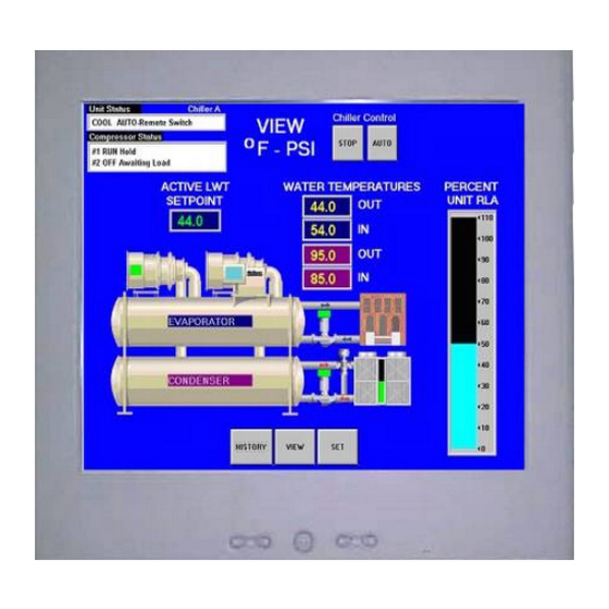
Page 18: Screen Descriptions
Dual compressor (WDC, WCC) units, as shown, will show two compressors and the status of both. Single Compressor units (WSC, TSC) will show only the one compressor. The pressures and temperatures shown are common to the unit and correct for both single and dual compressor chillers. - Page 19 Table 10, UNIT STATUS Combinations MODE STATE SOURCE COOL Manual Switch SHUTDOWN (Note 1) Remote Switch HEAT AUTO Local BAS Network TEST Note: Shutdown is the state of shutting down; vane close, postlube, etc. • COMPRESSOR STATUS is MODE followed by STATE followed by the SOURCE that is the device or signal that created the STATE.
- Page 20 Action Buttons for: • AUTO and STOP buttons, normal start (AUTO) and STOP button activates the normal start and shutdown sequence. These buttons are only active when the control is in the "Local Control" mode. This eliminates the possibility of inadvertently shutting off the unit locally when it is under control of a remote signal such as a BAS.
- Page 21 Figure 7, Expanded Power View Screen Pressing the EVAP or COND button will give detailed information on the evaporator or condenser pressures and temperatures. Pressing the MENU button on the bottom of the screen will go to a menu (see Figure 8) from which the above listed screens can also be accessed. Pressing the POWER button will access a screen showing power data for the unit.
- Page 22 Figure 9, View Compressor State Screen For example, pressing the Compressor-State button will yield the following screen superimposed on the right side of the Detail View Screen. The Compressor State screen is basically a compilation of the events that the chiller sequences through at startup.
-
Page 23: Set Screens
Figure 12, Bar Chart with Labels The bar chart screen is accessed from the MENU screen (Figure 8) by selecting LABELED BAR GRAPHS. Selecting BAR CHARTS will access the same graph, but without the labels. SET Screens The set screens on the Interface Panel are used to input the many setpoints associated with equipment of this type. - Page 24 Figure 13, A Typical SETPOINT Screen Setpoint Description Numeric Keypad Setpoint Setpoint Action Selection Groups Buttons Setpoints Initiate Buttons Change Button The above figure shows the SETPOINT screen with WATER setpoints selected. The various setpoint groups are in a column on the right side of the screen. Each button contains a number of setpoints grouped together by similar content.
- Page 25 4. Press the appropriate numbers in the numeric keyboard to enter the password. There is a small delay between pressing the keypad and recording the entry. Be sure that an asterisk appears in the window before pressing the next number. Press ENTER to return to the SETPOINT screen.
- Page 26 STARTER SETPOINTS Figure 14, Optional Starter Setpoint Screen Table 12, Starter Setpoints Pass- Description Default Range Comments word Sets the value for ground current above Ground Fault Current Trip 1 to 100% RLA which the compressor will be shut down Ground Fault Enable On or OFF Turns the ground fault option on or off...
- Page 27 TIMERS Setpoint Figure 15, TIMERS Setpoint Screen Table 13, TIMER Setpoints Pass- Description Default Range Comments word Postlube Timer 30 sec 10 to 240 sec Time for postlube before compressor can stop Unload Timer 30 sec 10 to 240 sec Time compressor will unload before going to postlube Full Load Timer 300 sec...
- Page 28 ALARMS Setpoint Figure 16, ALARMS Setpoint Screen Table 14, ALARM Setpoints Pass- Description Default Range Comments word Low Net Oil Pressure 50 psi 50 to 90 psi Min net pressure (feed minus sump) Low Oil Delta Temperature Min Delta-T (sat evap minus oil temp) 40 °F 20 to 80 °F High Oil Feed Temperature...
- Page 29 Cooling Tower Bypass VALVE Settings Figure 17, Tower Bypass VALVE Setpoint Screen Table 15, Tower Bypass VALVE Setpoints (See page 31 for complete explanation.) Pass- Description Default Range Comments word Slope Gain 10 to 99 Control gain for temperature (or lift) slope Error Gain 10 to 99 Control gain for temperature (or lift) error...
- Page 30 Cooling TOWER Fan Settings Figure 18, Cooling TOWER Fan Setpoint Screen (See page 31 for complete explanation.) Table 16, Tower Fan Settings Pass- Description Default Range Comments word Stage #4 On (Lift) 65 psi 10 to 130 psi Lift pressure for fan stage #4 on Stage #3 On (Lift) 55 psi 10 to 130 psi...
- Page 31 Explaination of Tower Control Settings MicroTech II control can control cooling tower fan stages, a tower bypass valve, and/or a tower fan VFD if the chiller has a dedicated cooling tower. The Tower Bypass Valve position will always control the Tower Fan Staging if Valve Setpoint, Stage Setpoint is selected.
- Page 32 Tower Fan Staging With Bypass Valve Controlling Minimum EWT (VALVE SP) 1) TOWER SETPOINT Screen a) SP1. Select TEMP if control is based on condenser EWT or LIFT if based on compressor lift expressed in psi. b) SP2. Select Valve SP for control of bypass valve based on temperature or lift. c) SP3.
- Page 33 NOTE: Setpoints 14 and 15 are site specific dealing with system fluid mass, component size and other factors affecting the reaction of the system to control inputs. These setpoints should be set by personnel experienced with setting up this type of control. c) If LIFT was selected for fan control, use SP3, Set the VALVE TARGET (setpoint), usually 30 psi below the minimum fan stage setpoint established in TOWER SP12.
- Page 34 Initial amps as % of RLA Limit Soft Load Enable OFF, ON Soft load on or off Nameplate RLA Not used on WSC/WDC models Maximum Amps 100% 40 to 100% % RLA above which loading is inhibited (Load Limit) Minimum Amps...
- Page 35 MODES Setpoints Figure 20, MODES Setpoint Screen Table 18, MODE Setpoint Settings Pass- Description Default Range Comments word Comp # 2 Stage Sets sequence number for # 2 compressor, if 1 it is 1,2, … (# of Compressors) Sequence always first to start, if 2 is always second (Note 1) Normal uses standard sequencing Normal, Efficiency, Pump, Efficiency starts one compressor on each dual unit...
- Page 36 WATER Setpoints Figure 21, WATER Setpoint Screen Table 19, WATER Setpoint Settings Pass Description Default Range Comments word Templifier Source Resets the condenser leaving temperature Water Reset downward if source leaving drops under the 55°F 50 to 100 °F (Delta-T) delta-T.
-
Page 37: Service Screen
Parts Manual button. Some early versions may not have a parts list loaded. A McQuay service technician can upload it. Pressing these buttons will display the manual on the screen where it can be manipulated as an Adobe Acrobat file®. -
Page 38: History Screens
HISTORY Screens Figure 23, History Trend Graph The Trend History Overview allows the user to view the various parameters listed on the right side of the screen. The temperature scale in °F (°C) is on the left. Pressure in psi (kPa) and % RLA are represented by the right-hand scale. -
Page 39: Download From The Usb
Figure 24, Alarm History/USB Download The Alarm History lists the alarms with the most current on top with date stamp, action taken and the cause of the alarm. The alarms are color-coded as shown on the top of the screen. Download from the USB This screen is also used to download the Trend History (Figure 23) selected by date or the Alarm History shown above. -
Page 40: Active Alarm Screen
ACTIVE ALARM Screen Figure 25, Active Alarms The Active Alarm screen is accessible when an active alarm exists on the unit by pressing the red alarm signal on any screen. If no alarm is active, it can be accessed from the SERVICE screen by pressing the blue square where the red alarm signal would be. - Page 41 Alarms fall into three distinct categories: Faults, Problems, and Warnings as detailed in the following section. Fault Alarms The following table identifies each fault alarm, its display, gives the condition that causes the alarm to occur, and states the action taken because of the alarm. All fault alarms require a manual reset and trigger the remote alarm signal.
- Page 42 Problem Alarms The following alarms do not cause compressor shutdown but limit operation of the chiller in some way as described in the Action Taken column. A limit alarm will trigger the red alarm screen but not the digital output for the optional remote alarm. Table 21, Problem Alarm Description Description Display...
-
Page 43: Unit Controller
Unit Controller A general description of the unit controller with its inputs and outputs is on page 7. This section will describe the operation of the unit controller, define the screen hierarchy and how to navigate through it and also give a description of the screens. 4x20 Display &... - Page 44 b) Depending on the top-level selected, a second level of screens will appear. For example, selecting ALARM will go the next level of menus under ALARM (ALARM LOG or ACTIVE ALARM). Selecting VIEW will go the next level of menus (VIEW COMPRESSOR STATUS, VIEW UNIT STATUS, VIEW EVAPORATOR, or VIEW CONDENSER).
- Page 45 Set Screens SET UNIT SPs SET COMP #1SPs (1) SET COMP#2 SPs (1) SET ALARM SPs (1) SET TOWER SPs (1) Enable = Demand Limit= Demand Limit= LowEv PrHold = TowerControl-Temp = Mode = Minimum Amps = Minimum Amps= Low Ev Pr Unld = TowerStages = Source = Maximum Amps=...
-
Page 46: Screen Descriptions
Screen Descriptions VIEW Screens VIEW Screens are only for viewing the operation of the unit and compressors. No data is input into VIEW Screens. The controllers’ screens are only in °F/psi. When the Display Units set point is set to °C/kPa, the units of measure on the OITS only will change. View Unit Status (Single Compressor) VIEW UNIT STATUS (1) Unit=COOL... - Page 47 VIEW UNIT WATER ° ° ° ° F(3) Water Flow Rates Evap = XXXX GPM Cond = XXXX GPM View Unit Refrigerant VIEW UNIT REFRG (1) ° ° ° ° F Sat Evap XXX.X XX.X Sat Cond XXX.X XX.X VIEW UNIT REFRG (2) Suct Line = XXX.X°...
- Page 48 VIEW COMP#N (2) Cond Press = Evap Press = Lift Press = VIEW COMP#N (3) Feed Press =XXXX psi Sump Press =XXXX psi Net Press = XXX psi VIEW COMP#N (4) Sump Temp = XXX.X° ° ° ° F Feed Temp = XXX.X° ° ° ° F Lift Temp = XXX.X°...
-
Page 49: Set Screens
View ALARM Screens View Alarm Log ALARM LOG (1) Alarm Description hh:mm:ss dd/mmm/yyyy ALARM LOG (2-25) Alarm Description hh:mm:ss dd/mmm/yyyy The ALARM LOG contains a description and time stamp on the last 25 alarms Active Alarm Screen Active Alarms ALARM ACTIVE (1) Alarm Description hh:mm:ss dd/mmm/yyyy <Press Edit to CLEAR... - Page 50 DEFAULT CANCEL MENU Air Conditioning < ALARM < VIEW < DECREMENT ENTER INCREMRNT These four edit functions are indicated by one-character abbreviation on the right side of the display (this mode is entered by pressing the ENTER key). Most menus containing set point values have several different setpoints shown on one menu. When in a setpoint menu, the ENTER key is used to proceed from the top line to the second line and on downward.
-
Page 51: Unit Controller Setpoints
Additional fields can be edited by pressing the ENTER key until the desired field is selected. When the last field is selected, pressing the ENTER key switches the display out of “edit” mode and returns the arrow keys to “scroll” mode. Unit Controller Setpoints Table 23, Unit Setpoints Description... - Page 52 Description Default Range Stage Down @ 0 to 100% Stage Up @ 0 to 100% Valve Control Range (Min) 0 to 100% Valve Control Range(Max) 0 to 100% Valve Type NC To Tower NC, NO Minimum Start Position 0 to 100% Minimum Position @ 60 °F 0 to 100 °F...
- Page 53 SET UNIT SPs (5) Reset Type =4-20mA MaxResetDT =XX.X° ° ° ° F StrtResetDT=XX.X° ° ° ° F Reset Type settings can be NONE, RETURN (return chilled water), or 4-20 (external input) as determined by the LWT Reset Type setpoint. SET UNIT SPs (6) Soft Load = OFF...
- Page 54 SET UNIT SPs (12) CLOCK dd/mmm/yyyy hh:mm:ss SET UNIT SPs (13) Units = ° ° ° ° F/psi Lang = ENGLISH SET UNIT SPs (14) Protocol = Ident Number + Baud Rate = SET UNIT SPs (15) Ex Valve Gain = 100 Offset(Slope) = 271 Prs Ctrl Dout = 10°...
- Page 55 Figure 31, Pressure Control Dropout 80° F PRESSURE CONTROL MODE (PULLDOWN) LEAVING CHILLED WATER TEMP DROP OUT TEMP PROGRAM CONTROL MODE LWT SETPOINT 40° F TIME Set Compressor Setpoints SET COMP#N SPs (1) Demand Limit = OFF Minimum Amps =XXX% Maximum Amps =XXX% Demand Limit settings can be OFF or ON as determined from the Demand Limit setpoint.
- Page 56 SET COMP#N SPs (3) StageDeltaT= X.X° ° ° ° F Stop-Start = xx min. Start-Start =xx min. SET COMP#N SPs (4) Full Load = XXX sec SET COMP#N SPs (5) OilNoStrtDiff=XX° ° ° ° F Abs Capacity=XXXXT HotGasBypass = XX% SET COMP#N SPs (6) UnloadTimer=XXXsec PrelubeTmr=xxxsec...
- Page 57 Staging Parameters Full Load Determination Each compressor determines if it is at its maximum capacity (or maximum allowed capacity) and, if so, set its Full Load flag. The flag shall be set (full load) when one or more of the following conditions are met.
- Page 58 Set Alarm Setpoints SET ALARM LMTS (1) LowEvPrHold=XXXpsi LowEvPrUnld=XXXpsi LowEvPrStop=XXXpsi SET ALARM LMTS (2) HighCondPr=XXXXpsi HiDschT-Load=XXX° ° ° ° F HiDschT-Stop=XXX° ° ° ° F SET ALARM LMTS (3) HiOilFeedTmp=XXX° ° ° ° F LowOilDeltaT =XX° ° ° ° F LowNetOilPr=XXXpsi SET ALARM LMTS (4) HighSSH-Start=XX°...
- Page 59 SET TOWER SPs (4) Valve/VFD Control= ValveSP/VFDStage Valve Type = NC Valve/VFD Control settings are None, Valve Setpoint, Valve Stage, VFD Stage, or ValveSP/VFDStage. Valve Type settings are NC (normally closed to tower) or NO (normally open). To w er Co nt ro l = Temp/No ne To w er Co nt ro l = Lif t SET TOWER SPs (5) SET TOWER SPs (5)
- Page 60 Alarms When an alarm occurs, the alarm type, limit value (if any), date, and time are stored in the active alarm buffer corresponding to that alarm (viewed on the Active Alarm screen) and also in the alarm history buffer (viewed on the Alarm History screen). The active alarm buffers hold a record of the last occurrence of each alarm and whether or not it has been cleared.
-
Page 61: Compressor Controller
Compressor Controller A general description of the unit controller with its inputs and outputs is on page 8. This section will briefly describe the operation of the controller, define the screen hierarchy and how to navigate through it and also give a description of the screens. Relevant compressor information and setpoint changes are available on the OITS and on the unit controller. -
Page 62: Compressor Controller Setpoints
For example, selecting ALARM will go the next row of menus under ALARM (ALARM LOG or ACTIVE ALARM). Selecting VIEW will go the next level of screens under VIEW (VIEW UNIT STATUS or VIEW UNIT TEMP). Selecting SET will go to a series of screens for looking at and changing setpoints. - Page 63 Table 24, Compressor Setpoints Description Default Range Unit (Duplicates) Unit Enable OFF, ON Unit Mode COOL COOL, ICE, HEAT, TEST Cool LWT 44. 0°F 35.0 to 80.0 °F Ice LWT 25. 0°F 15.0 to 35.0 °F Heat LWT 135. 0°F 100.0 to 150.0 °F Startup Delta T 3.0°F...
- Page 64 SET COMP#N SPs (1) Demand Limit = OFF Minimum Amps =XXX% Maximum Amps =XXX% Demand Limit settings can be OFF or ON as determined from the Demand Limit setpoint. SET COMP#N SPs (2) StageMode = NORMAL StageSequence# =XX Max Comprs ON = XX StageMode settings can be NORMAL, HI EFF, PUMP, and STANDBY as determined by the Stage Mode setpoint.
- Page 65 SET COMP#N SPs (6) UnloadTimer=XXXsec PrelubeTmr=xxxsec PostlubeTmr=XXXsec B ef o re Ent ering Edit M o de Af t er Ent ering Edit M o de SET COMP#N (7) SET COMP#N (7) VaneMode=AUTO VaneMode=AUTO <AUTO Vanes=UNKNOWN Vanes=UNKNOWN <LOAD %RLA = XXX% %RLA = XXX% <UNLD VaneMode settings can be AUTO or MAN (Manual) as determined from the Vane Mode setpoint.
- Page 66 The Vanes Open digital input is On AND the VFD speed = 100%. • The %RLA is above or equals the Maximum Amp limit set point. • The %RLA is above or equals the Demand Limit analog input value • The %RLA is above or equals the Network Limit value •...
-
Page 67: Optional Starter Screens
Optional Starter Screens Figure 34, Optional Starter View Screen The ability to view the starter(s) electrical performance and to set starter setpoints on the operator interface screen is an optional extra available at the time of purchase. If the option is supplied on the unit, the “STARTER” button will be visible on the upper left side of the VIEW screen as shown above. -
Page 68: Low Voltage Starters, 200 - 600 Volts
Low Voltage Starters, 200 – 600 Volts This section contains information on low voltage, Wye-Delta and solid-state starters as manufactured by Benshaw Inc. for McQuay centrifugal Chillers. They are known collectively as “D3” starters. These low voltage starters have similar hardware and software (designated D3) and are grouped together in this manual. -
Page 69: Led Display
Figure 37, Solid State Starter, Wall Mounted Terminal Strip Disconnect Switch Primary Control Circuit Fuses Controller, D3 LED Display SCRs (Behind) Bypass Contactor Control Transformer LED Display There is an LED display and keypad within the starter enclosure as shown in Figure 36 and 39. It is used to set parameters (setpoints) and to view the operation of the motor/starter. - Page 70 The starter setpoint parameters are factory set and subsequently reviewed during commissioning by the McQuay startup technician. They should not be changed unless authorized by McQuay. The programming procedure is explained above and the following table shows the range of values and defaults.
- Page 71 Table 25, Setpoints, Wye-Delta Starter Description Values Default Motor RLA 1 to 9999 Amps Motor Service Factor 1.00 to 1.99 1.08 Motor Overload Class OFF, 1 to 40 Transition Time 1 to 30 seconds Default Meter Display 0 to 19 Sequence Complete Delay Time 0.1 to 5.0 seconds Overcurrent Trip Level...
- Page 72 Description Values Default Current Imbalance Trip Level 5 to 40 % Controlled Fault Stop OFF, On Auto Fault Reset Time OFF, 1 to 120 seconds 72, 96, 144, 288, 864, 2640, CT Ratio 2640 2880, 5760, 8000 Ter: Terminal Control Source Net: Network Modbus Address 1 to 247...
- Page 73 Table 29, Default Meter Display 0: Status Message 7: Ave L-L Voltage RMS 14: KVA 1: Ave RMS Current 8: L1-L2 Voltage RMS 15: KWh 2: L1 RMS Current 9: L2-L3 Voltage RMS 16: MWh 3: L2 RMS Current 10: L3-L1 Voltage RMS 17: Phase Rotation 4: L3 RMS Current 11: Overload %...
-
Page 74: Faults And Alarms
Overload meter Toggle between the programmed meter display and the overload content by pressing the DOWN key. The overload will be displayed as “oXXX” where XXX is the overload content. For example if the overload content is 76 percent, it will be displayed as “o 76”. Phase Order Meter Toggle between the programmed meter display and the phase order by pressing the UP key. - Page 75 Description Auto Reset CPU Error – Illegal Instruction Trap CPU Error – Software Watchdog Fault CPU Error – Spurious Interrupt CPU Error – Program Storage Fault NOTE: If a fault occurs that has a Y in the “Auto Reset” column, and P14 (Auto Fault Reset Time) is set to some value other than OFF, then the fault will automatically be cleared after the time specified by P14.
- Page 76 Alarm Definitions The following is a list of all D3 alarm codes. The alarm codes correspond to associated fault codes. In general, an alarm indicates a condition that if continued, will result in the associated fault. Table 32, Alarm Codes Alarm Description Notes...
-
Page 77: Troubleshooting
Alarm Description Notes Code This alarm exists while the D3 is running and the average current is above the defined threshold, but the Overcurrent delay for the fault has not yet expired. When the delay expires, a Fault 31 will occur. This alarm exists while the D3 is running and the average current is below the defined threshold, but the Undercurrent... - Page 78 Check for proper control voltage input. Display Blank, Heartbeat Control voltage absent. Verify wiring and fuses. LED on D3 board not blinking. D3 control board problem. Consult McQuay Service. Table 36, Metering incorrect Condition Cause Solution Shut off all power and check all Loose connections.
- Page 79 Condition Cause Solution Verify fan power supply, check Fan power supply lost fuses. Starter cooling fans(when present) do not operate Fan wiring problem Check fan wiring. Fan failure Replace fan Verify that the remote keypad Keypad cable not plugged in cable has not been damaged and properly or cable damaged.
- Page 80 Fault Description Detailed Description of Fault / Possible Solutions Code Verify that input power is three phase. Correct wiring if necessary. Low voltage below the Undervoltage Trip Level parameter setting (PFN 08, P31) was detected for longer than the Over/Under Voltage Trip delay time (PFN 09, P32).
- Page 81 Fault Description Detailed Description of Fault / Possible Solutions Code A current imbalance larger than the Current Imbalance Trip Level parameter setting (PFN 05, P28) was present for longer than ten (10) seconds. Current Check motor wiring for cause of imbalance. (Verify dual voltage and 6 Imbalance lead motors for correct wiring configuration).
-
Page 82: Preventive Maintenance
EEPROM If fault persists after performing a Factory Parameter reset, consult Checksum Fault McQuay Service. The D3 control has detected an internal CPU problem. Consult McQuay CPU Error Service. CPU Error – SW The D3 control has detected an internal software problem. Consult Watchdog Fault McQuay Service. -
Page 83: Medium/High Voltage Starters, 2300V - 7.2Kv
This section contains information on medium voltage, across-the-line and solid state starters as manufactured by Benshaw Inc. for McQuay centrifugal Chillers. Medium voltage starters have similar software (Micro II) and are grouped together in this manual. Model numbers are as... -
Page 84: View Parameters
The starter’s setpoint parameters are factory-set and subsequently reviewed during commissioning by the McQuay startup technician. They should not be changed unless authorized by McQuay. The programming procedure is explained below and the following table shows the range of values and defaults. - Page 85 Menu Structure The Micro II control has a 2 level menu structure. There are eight main menus that contain parameters related to the different functions of the starter and five of the main menus contain additional sub-menus that divide the parameters into functional groups. The following shows the structure of the menu structure.
-
Page 86: Quick Start
Quick Start Motor FLA Parameter Description The motor FLA parameter must be set to the full load amps of the motor connected to the starter for the starter to function correctly. NOTE: The starter uses the entered motor FLA for every current based calculation. If the motor FLA is not entered correctly, the current ramp profile and many of the starter’s advanced protection features will not function properly. - Page 87 If the motor does not rotate within a few seconds after a start command, the initial current should be increased. If the motor takes off too quickly after a start command, the initial current should be decreased. The initial current must be set to a value that is lower than the maximum current parameter setting. A typical setting for the initial current parameter is from 50% to 175%.
-
Page 88: Troubleshooting
Phase Order Description The line phasing parameter sets the phase sensitivity of the starter. This can be used to protect the motor from a possible change in the incoming phase sequence. If the incoming phase sequence does not match the set phase rotation, the starter will display phs err while stopped and will fault if a start is attempted. - Page 89 Table 44, Other situations. Display Cause Solution Power Metering not Fix CT installation. White dot to line CT installed wrong. working. side. TruTorque Ramp CT installed wrong. Fix CT installation. White dot to line side not working. Motor current Motor Verify motor is operating correctly.
-
Page 90: Fault/Log Codes
Fault/Log Codes The following is a list of the possible fault and log codes that can be generated depending on the type of starter. The fault class lists the default setting for each fault; either critical or non-critical. NonC = Non-critical Crit = Critical Table 45, Fault/Log Codes Fault/... - Page 91 Fault/ Fault Fault/Event Description/Possible Solutions Clas Recorder Text The door mounted keypad has failed. Crit Key Pad Failure The Stop or Start button was held down while a computer reset was performed or while power was applied to the unit. During TruTorque ramping, the motor current exceeded the TruTorque Crit TT Overcurrent Limit...
- Page 92 Fault/ Fault Fault/Event Description/Possible Solutions Clas Recorder Text The start/stop circuitry has failed. Crit Unauthorized RUN A fast start/stop sequence was performed. Check wire connected to terminal JC13-3. A shorted SCR on line 1 was detected Crit Shorted SCR • Check all 3 SCRs for shorts A shorted SCR on line 2 was detected.
-
Page 93: Led Diagnostics
LED Diagnostics There are several LEDs located on the Micro II circuit cards. These LEDs can be used to help troubleshoot problems with the starter. Refer to the circuit card layouts for LED locations. Table 46, LED Diagnostics CARD LED # NAME INDICATION Watch Dog/Power... -
Page 94: Sequence Of Operation
(16 total), the code works the same rather in a standalone WSC, or in a Dual (2 chiller) WDC setup. The Max Comp On setpoint is used to limit the number of compressors that can run at one time (not the number being polled). - Page 95 2. Once the lead compressor has satisfied the Soft Loading requirement, and judged to be at Full Load, the Lag compressor (on multiple compressor applications) will determine when to stage up as follows. 3. The Lag compressor will initiate a start sequence when the following events occur: a) Full Load flag received from lead compressor, b) Evap LWT slope is less than minimum pull down rate, c) Evap LWT exceeds the Stage-Delta-T setpoint.
-
Page 96: Operating The Chiller Control System
The Compressor's Full Load Status indication is set up into two modes, with and without VFD. 1. With VFD - Full Load is indicated with Vanes_Open and VFD Speed (>100%). 2. Without VFD - Full Load is indicated when SoftLoad is not active, and any of the following logic or flags are set;... -
Page 97: Change Setpoints
Change Setpoints Set points are easily changed on the Operator Interface Touch Screen (OITS). A complete description of the procedure begins on page 24. Set points can also be changed in the unit controller but this is not recommended except in an emergency when the OITS is unavailable. Alarms A red ALARM light in the lower middle of any screen is illuminated if there is an alarm. -
Page 98: Maintenance Schedule
Maintenance Schedule aintenance Check List Item I. Unit · Operational Log · Analyze Operational Log · Refrigerant Leak Test Chiller · Test Relief Valves or Replace II. Compressor · Vibration Test Compressor A. Motor · Meg. Windings (Note 1) · Ampere Balance (within 10% at RLA) ·... - Page 99 McQuay's high efficiency heat exchangers have very low design approach temperatures, in the order of one to one and one half degrees F.
- Page 100 This document contains the most current product information as of this printing. For the most up-to- date product information, please go to www.mcquay.com. All McQuay equipment is sold pursuant to McQuay’s Standard Terms and Conditions of Sale and Limited Product Warranty. Consult your local McQuay Representative for warranty details. Refer to form 933-43285Y.
Need help?
Do you have a question about the WSC and is the answer not in the manual?
Questions and answers