
Related Manuals for McQuay MicroTech II N2


Summary of Contents for McQuay MicroTech II N2
- Page 1 Installation and Maintenance Manual IM 730-0 Group: McQuay Controls Date: July 2002 MicroTech II™ AAF®HermanNelson® Unit Ventilator Controller N2 Open Communication Modules © 2002 McQuay International...
-
Page 2: Table Of Contents
To mount a new MicroTech II N2 communication module onto the Unit Controller board, follow these steps: ......................... 9 To replace a MicroTech II N2 communication module on a MicroTech II Unit Controller board, follow these steps: ........................10 SERVICE INFORMATION ......................12 ........................... - Page 3 Limited Warranty Consult your local McQuay Representative for warranty details. Refer to Form 933-43285Y. To find your local McQuay Representative, go to www.mcquay.com. Revision History IM 732 August 1, 2002 Initial Release Reference Documents Number Source Title OM748 www.McQuay.com Air Source Heat Pump with Electric Heat (Software Model 00) OM749 www.McQuay.com...
-
Page 4: General Information
Controller board and to make the wiring connections to your network. You also need the appropriate McQuay Engineering Data Sheet known as the Protocol Information to integrate the unit into your network. The Protocol Information contains addressing details, N2 Open protocol information, and a list of the data points available to the network. -
Page 5: Application
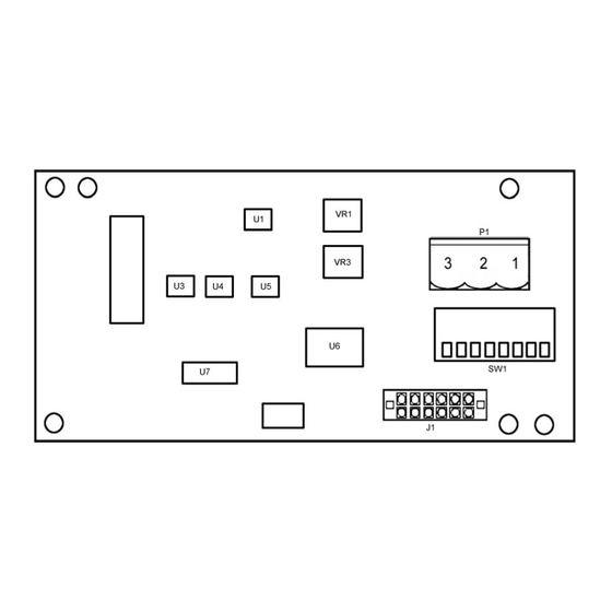
Figure 1: N2 communication module Application The MicroTech II N2 communication module connects the MicroTech II Unit Controller to the Building Automation System (BAS) on a N2 Local Area Network. It is the interface for the exchange of N2 points between the network and the Unit Controller. -
Page 6: Address Switch
(0 + 0 + 4 + 8 + 0 +0 +64 +0 =76) 12-Pin Header The 12-pin header, J1, connects the unit-controller Unit Controller board to the MicroTech II N2 Open communication module through the bottom side of the printed-circuit board. -
Page 7: Integration
Integration Configuring the Unit Controller Each MicroTech II Unit Controller board and N2 communication module is preprogrammed and configured at the factory to be a single Unit Controller, whether the boards are assembled together at the factory or field assembled. Each unit is also ready to operate using the default values. These default values may be changed via the unit’s keypad, using ServiceTools™, or via the network. -
Page 8: N2 Bus Rules
N2 Bus Rules Figure 6 summarizes the rules and maximums allowed for installing the N2 Bus. You may wish to print this table and keep it handy. Figure 6. N2 Bus Rules Category Rules/Maximums Allowed One or two N2 Bus per NCM General Only daisy-chained devices 100 devices per NCM (60 to 200 TC-9100s) -
Page 9: Installation
Installation The MicroTech II N2 Open communication module may either be installed in the factory or field installed. The module mounts on connector pins and is held in place with three plastic locking standoffs. The N2 Open network connects to the MicroTech II N2 Open communication module at the network connector plug (SG1). -
Page 10: Follow These Steps
2. Record the N2 address on the Address Switch (SW1). 3. Remove the network cable plug-in connector from the SG1 terminal block (see Figure 2). 4. Locate the three standoffs for the MicroTech II N2 communication module on the Unit Controller board (Figure 7 and Figure 8). -
Page 11: Figure 8. Communication Module Mounting Detail
Figure 8. Communication module mounting detail Figure 9. N2 module typical wiring IM 730-0... -
Page 12: Service Information
Check the integrity of the cable harness to the network terminals • Verify that the N2 address (SW1) is set to a unique binary number between 1 and 253. If the MicroTech II N2 Open communication module still doesn’t respond, replace the communication module. List of Replaceable Parts...
Need help?
Do you have a question about the MicroTech II N2 and is the answer not in the manual?
Questions and answers